Getting Started
I
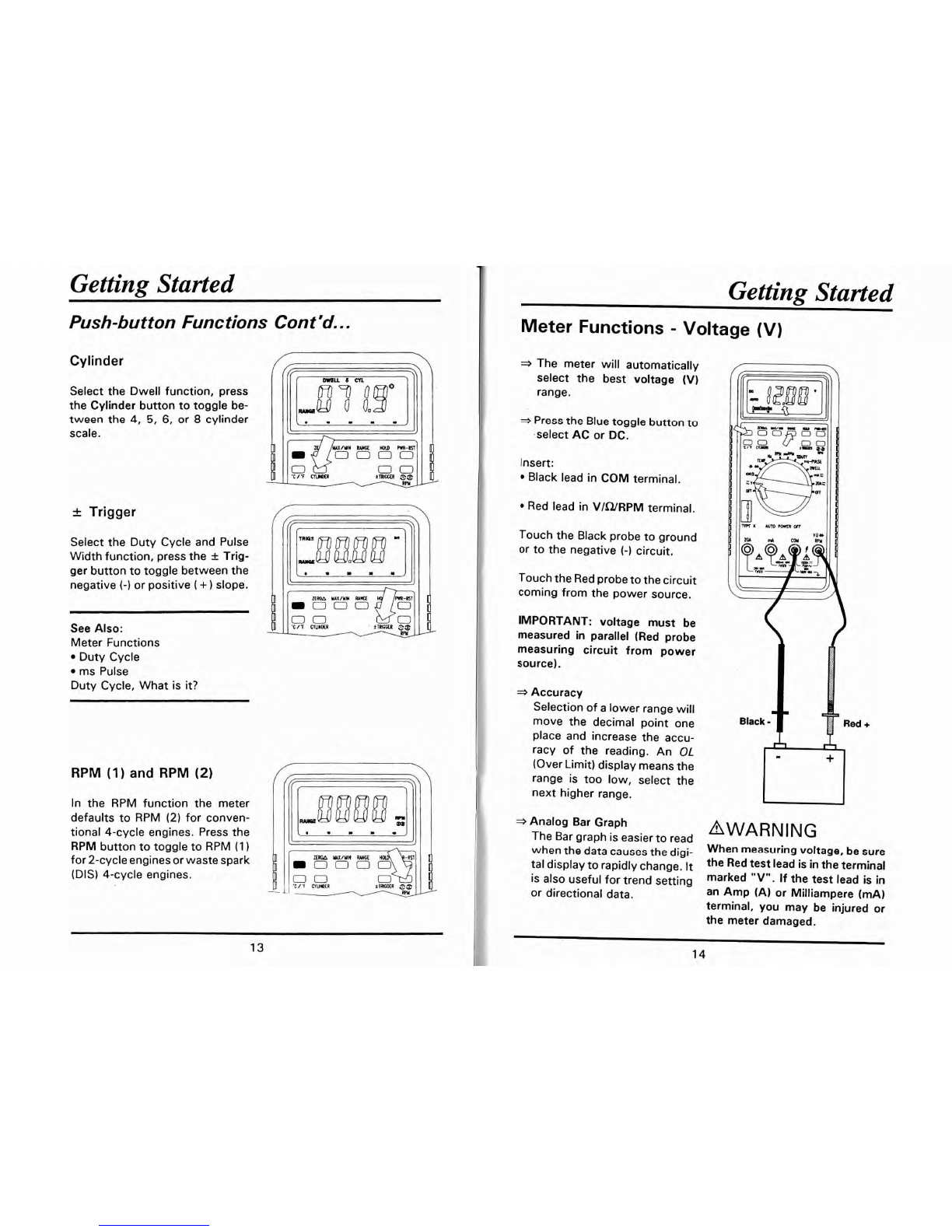
Getting Started
Push-button Functions Cont'd..
.
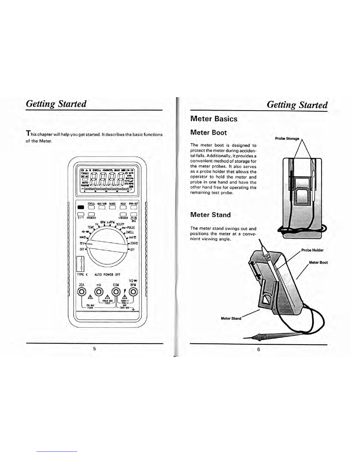
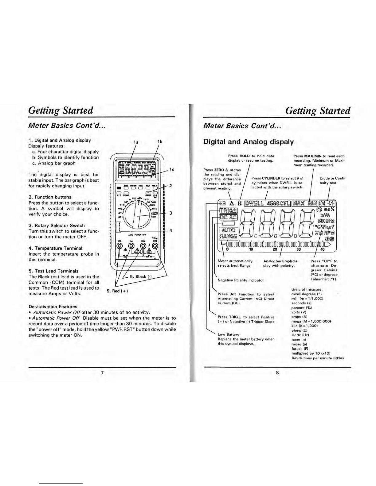
Data Record (MAXIMIN)
The Data Record feature stores
the highest or lowest reading in
memory.
First, connect the meter probes
to the test points. Then, press
the MAXIMIN button once to
start MIN recording. The mini-
mum readingwill be displayed.
PresstheMAXIMINbuttontwice
tostartthe MAXrecording.The
maximum reading will be dis-
played.
Press the HOLD button to stop
the recording, press again to
restart the recording.
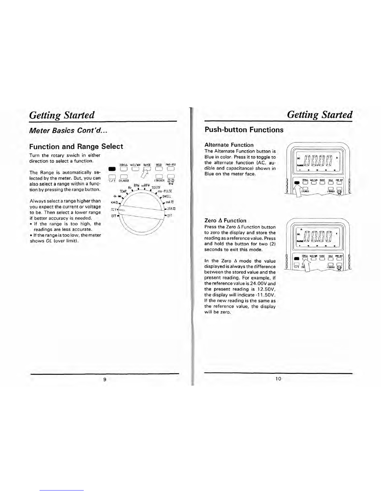
Range Select
The range is automatically se-
lected by the meter. But, you can
alsomanuallyselectarangewithin
afunctionbypressingthe RANGE
button.
Range Exit
To exit the RANGE mode and
return to autoranging, press and
hold the RANGE button for
2
seconds.
Note:
If the range is too high, the
readings are less accurate.
If therangeis toolow, themeter
shows
OL
(over limit).
Push-button Functions Cont'd..
.
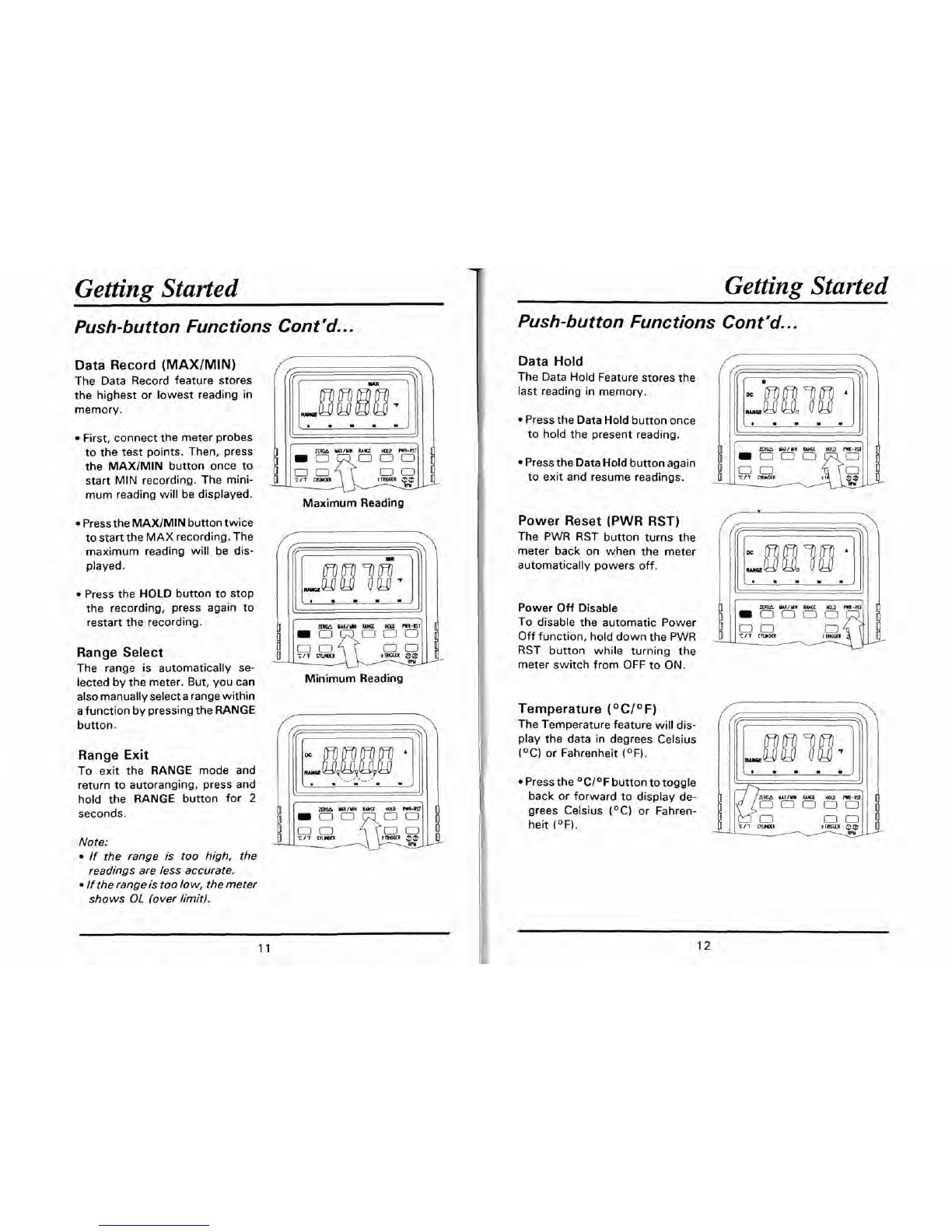
Data Hold
-
The Data Hold Featurestores the
(
ffr
3%)
\
last reading in memory.
Pressthe DataHoldbuttononce
to hold the present reading.
I
1:
I
I
Pressthe DataHoldbuttonagain
to exit and resume readings.
I
Maximum Readina
111:
TIT
CRHas
:y%EJ,
Minimum Reading
I
Power Reset (PWR RST)
The PWR RST button turns the
meter back on when the meter
automatically powers off.
Power Off Disable
To disable the automatic Power
Off function, hold downthe PWR
RST button while turning the
meter switch from OFF to ON.
Temperature (OCI0F)
TheTemperaturefeature will dis-
play the data in degrees Celsius
(OC) or Fahrenheit (OF).
Pressthe OCI°F buttontotoggle
back or forward to display de-
grees Celsius (OC) or Fahren-
heit (OF).
ZUlM
WlUW
M
HOW
m-m
G,U,
111-
02