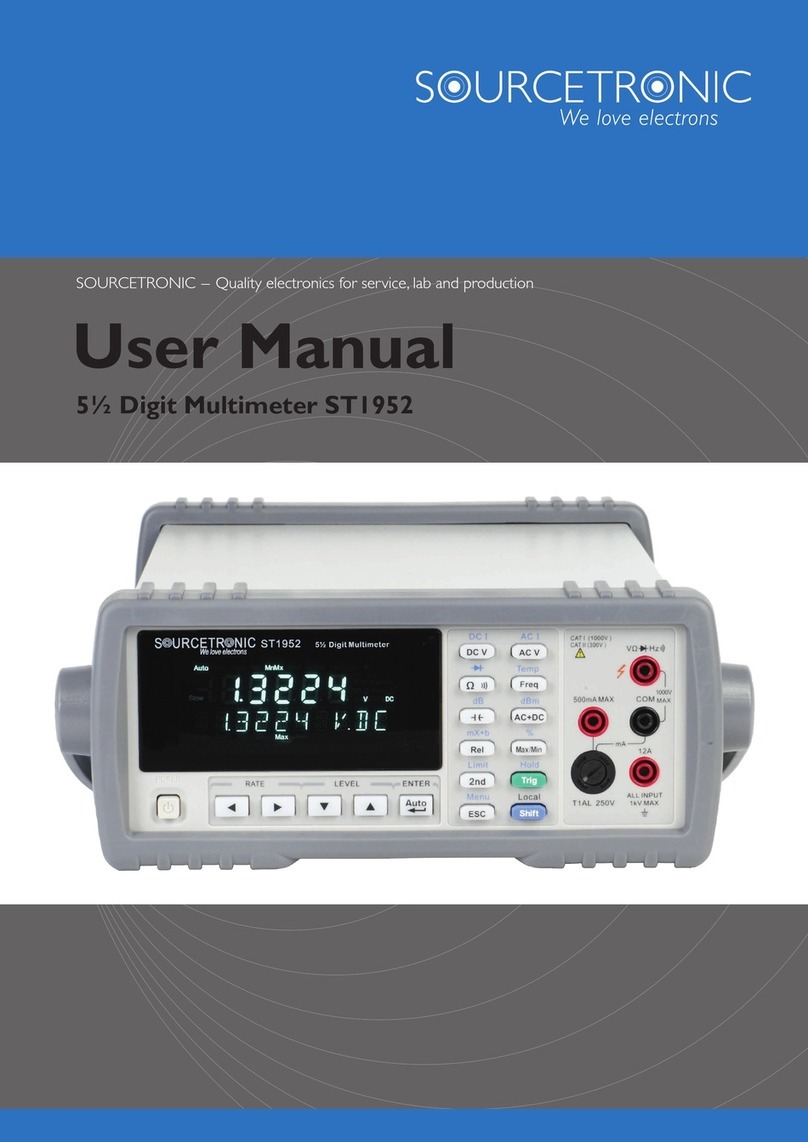
PDi 872 User manual

OPERATING INSTRUCTIONS
Model
872
DIGITAL
MULTIMETER

CONTENTS INTRODUCTION
Thismanualcontains informationandwarnings which mustbefollowed
to ensure safe operation and retain the meter in safe condition.
WARNING
READ "SAFETY INFORMATION" BEFORE
USING
THE
METER.
This multimeter is a handheld, 4000-count instrument that is designed
for use in the laboratory, field servicing, and at home. The meter
I
combines the precision of a digital multimeter with the high speed and
versatility of a analogdisplay. Thismeter featurescompactdesign with
rounded corners for easy handling and has a rugged case in shock
resistant and fire-retardant. Electronic overload protection for all
functions and ranges. The Protective Holster (optional accessory)
combined with rugged casemake it a durableand reliable instrument.
UNPACKING AND INSPECTION
Upon removingyournew Digital MuItimeter(DMM) from itspacking,
you should have the following items:
1.
Digital Multimeter
2. Test Lead Set (oneblack, one red)
'
3. 9-Volt Battery (installed in meter)
4.
Beaded Thermocouple Wire
5. Instruction Manual
6.
OneSpare Fuse (500mA/600V, 6.3mm
x
25mm, fast acting)
f
If
any of the above items are missing or are received in a damaged
cond~tion,please contact thedistributorfrom whom you purchased the
unit.

SAFETY
INFORMATION
Injury ordeath can occureven with low voltages and low currents. It is
extremely importantthatyou read thesesafety informationbeforeusing
your multimeter. Follow all safety practices and proper operating
procedures for equipment being tested.
1.
Exercise extremecaution when:
Measuring voltage above 20 volts, measuring current greater than
IOmA, measuring AC power line with inductive loads, measuring
AC power line during electrical storms.
2.
Always inspect your DMM, test leads and accessories for any sign
of damage or abnormality before every use. If any abnormal
conditions exist (i.e., broken or damaged test leads, cracked case,
display not reading, etc.), donot attempt to takeany measurements.
3.
Neverground yoilrselfwhen taking electrical measurements.Donot
touch exposed metal pipes, outlets, fixtures, etc., which might be at
ground potential. Keepyour body isolated fromground byusing dry
clothing, rubber shoes, rubber mats, or any approved insulating
material.
4.
Never touch exposedwiring, connections,testprobetips, oranylive
circuit conductors when attempting to make measurements.
5.
Never replace the protective fuse insidethe DMM with afuseother
than the specified orapproved equal fuse.
6.
Do not operate this instrument in an explosive atmosphere (i.e., in
the presence of flammable gases or fumes, vapor or dust.)
7.
Measuring voltage which exceeds the limits of the multimeter may
damagethemeter and exposetheoperator toashockhazard. Always
recognizethemetervoltagelimits asstated onthefrontofthemeter.
8.
Never apply more than SOOVDC between the COMjack and earth
ground.
9.
Never touch a voltage source when the test leads are plugged into
a
current jack.
10. When testing for the presence of voltage orcurrent, make surethe
voltageorcurrent ranges are functioning correctly. Takea reading
of a known voltage or current before assuming a zero reading
indicates no current or voltage.
SYMBOL
EXPLANATION
9
-L
-
-
-
,,
,
14
I))
Attention! Refer to the Operating Instructions
Dangerous Voltage May Be Present at terminals
Ground
AC
-
Alternating Current
DC
-
Direct Current
Diode
Audible Continuity
Double Insulation

INSTRUMENT LAYOUT
1
VQHzCx* Volt, Ohms, Frequency, Capacitance,
Diode, InputTerminal
I
This is the positive input terminal for all functions except current
I
measurements. Connection is made to it using the Red test lead.
1
2
COM Common Terminal
This is the negative (ground) input terminal for all measurement
modes. Connection is made to it using the Black test lead.
3
mA
Millianlp Input Terniinal
11
This is the positive input terminal for current measurement (ac or
I
12
dc) up to
400
mA. Connection is made to it using the Red test lead.
13
4
20A
20
Amperes Input Terminal
10
This is the positive input terminal for current measurement (ac
or
dc) up to
20A.
Connection is made to it using the Red test lead.
I
'
5
Function
I
RangeSelector Rotary Switch
This rotary switch selects function and range needed. Each time the
5
rotary switch is ~iiovedfrom
OFF
to
a
function setting, all LCD
~
segments will turn on for one second.
6
PWR-RST Button
When the meter is automatic power-off, press the button to turns
meter back on.
Note: Disable Aulomntic Power-off
Ifyoupress and hold down the (PWR-RST) button whileturningthe
meterfrom
OFF
toonand selecta function,
theautomatic power-off
feature is disabled.
7
RESET Button
Press (RESET) button to erase the stored reading, and all LCD
segments will turn on for one second.

8
MEM Button
When (MEM) button is pressed, the "MEMO annunciator is dis-
played and thelast reading isstored onthe meter. If themeterpower
downautonnaticallyand thepowerback onby pressing (PWR-RST)
button, these stored readings will remain in memory.
9
READ
Button
Press (READ) button to recall thedata you stored in memory, the
readings will bedisplayed on the LCD, the "HOLD" annunciator
turnson, and the "MEM"annt~nciatorwillbedisplayedwitha blink.
Theautomatic power-off feature is disabled. Press (HOLD)button
to exit the READ mode.
10
REL
A
Button
Press (REL) button to enter the Relative mode, the "RELA
"
annunciator turns on, zero the display, and store the displayed
readindg asa reference value. Press and hold downthe(REL)button
for
2
seconds to exit the relative mode.
In the Relative
node,
the value shown on the LCD is always the
difference between the stored reference value and the present
reading. For example,
if
the reference value is 24.00V and the
present reading is 12.50V,the display will indicate -1 1.50V. If the
new reading is the same as the reference value, the display will be
zero.
11
MIN
I
MAX Button
Press(MIN
/
MAX)button toentertheMINMAXRecordingmode.
Theminimum, ~naxirnumvalues arethen reset to the present input,
the readings are stored in memory, and the "HOLD"annunciator
turns on. Push the.button to cycle through the minimum (MIN),
maxirnum (MAX), and present readings. The MIN or MAX
annunciator turns on to indicate what value is being displayed.
In the MIN MAX Recording mode, press (HOLD) button to stop
the recording of readings, press again to restart recording. If
recording is stopped, the minimum, maximum, or present values
and analog display are frozen. In the MIN MAX Recording mode,
when a new tnini~numvalue is exceed theactual minimum readings
ora new maxitnuln value is overload, the minimum ormaximum
value
willheld onthedisplay,but theanalogdisplaycontinuestobe
active.
12
HOLD
Button
Press (HOLD)button to toggle in ant1 out of the Data Hold mode,
except if you are already in the MIN MAX Recording mode.
In the Data Hold mode, the "HOLE" annunciator is displayed and
the last reading is held on the display, the beeper emits a tone, and
theauto~naticpower-off featureisdisabled. Pressing(MIN
/
MAX)
button when you are in the Data Hold modecausesyou to exit Data
Hold and enter the MIN MAX Recording mode.
13
RANGE
Button
Press (RANGE) button to select the Manual Range mode and turn
offthe "AUTO"annunciator. (Themeter remains in therangeit was
in when manltal ranging was selected).
In the Manual Range mode, each timeyou press (RANGE) button,
the range (and the input range annunciator) increments, and a new
value is displayed. To exit the Manual Range mode and return to
autoranging, press and hold down (RANGE) button for
2
seconds.
The "AUTO" annunciator turns back on.
14
Temperature.Jack
Thetemperaturejack is located in the lower left-hand cornerofthe
front panel.
To
measure a wide range of temperature
(-30°C
to
+
1300°C), plug in
a
K-type thermocouple and take the reading
direct from the digital display.

HOW
TO
MAKE MEASUREMENTS
Before making any measurements always examine the instrument
and accessories used with the instrument fordamage,contamination
(excessive dirt, grease, ect.) and defects. Examinethe test leads for
cracked orfrayed insulation and make surethe lead plugs fit snugly
into the instrument jacks. If any abnormal conditions exist do not
attempt to make any measurements.
VOLTAGE MEASUREMENTS
1.
Insert the black and red test leads into the COM and V-0 input
terminals respectively.
2. Select the desired AC voltage range
(
V-),( mV-) orDC voltage
range
(
V
--
).
WARNING
To avoid possible electric shock, instrument damage and
1
or
equipmentdamage, donot attempt totake anyvoltagemeasurements
if the voltageisabove IOOOVdc
/
750Vac. 1OOOVdcand 750Vacare
the maximum voltages that this instrument is designed to measure.
The "COM"terniinal potential should not exceed 500Vmeasuredto
ground.
3. Connect the test lead tips in parallel with the circuit to be measured
(e.g. across a load or power supply). Be careful not to touch any
energised conductors. Note the reading.
4.When all measurements arecompleted,disconnect the test leadsfrom
the circuit i~ndcrtest. Remove test leads from the multimeter.
For DC voltage readings, the RED lead tip should be connected to
thepositivesitleofthecircuit, the BLACK lead tothe negativeside.
A minus sign on the left hand sideof the LCD will appear if theleads
are connected thc other way round.
CURRENT MEASUREMENTS
These are made in series with the test circuit. All the current to be
measured flows through the multimeter.
WARNING
Donot attempt to measure currents in high energycircuitscapable
of delivering greater than 600V. Since the fuse is rated at 600V
damageorinjury could occur. The20A input terminal is protected
by a20Al600V high energy,fastblow fuse. The
mA
input terminal
is protected by a 500mAl600V fast blow fuse.
Do not exceed the limits of each current input terminal. This is 20A
(maximum time limit of 30seconds for currents greater than 10A) for
the 20A terminal and 400mA for the mA terminal.
All current ranges are fused. If a current greater than 20A on the 20A
rangeorgreaterthan500mA on all otherranges flows, thefusewill blow
causing an open circuit between the current measuring terminals.
1.
Insert the BLACK test lead in the COM input terminal.
2. Formeasuring currents lessthan 4001nA,connectthe
RED
test lead
to the mA input terminal. For measuring currents between 400mA
and 20A connect the RED test lead to the 20A terminal.
3. Select the desired AC current range (A-
)
or DC current range
(A=).
r
NOTE:
If the20A range is selected then the 20A input terminal must
beselected in step2. If the4mA, 40mA or400mA range is selected
the mA input terminal must be selected in step 2.
a
4. Switch OFFordisconnect the circuit to bemeasured from all power
sources,connect themultimeter in serieswith theconductorin which
the current to be measured flows.
5.
Switch ON the circuit. Note the reading.
6. Switch OFFor disconnect the circuit and remove the test leads from
multimeter.

CAUTION
A
common abuse of multimeters is to attempt to measure a voltage
whilethe test leadsarestill plugged into thecurrent input terminals.
This basically puts a short circuit across the voltage source since
current ranges have a low impedance. If the voltage source is
typically 240VACora 3-phaseindustrial voltage (415V),very high
fault currents can result. This is why all current input terminal are
fused. If the fusesblow they must only be replaced by theequivalent
ones otherwise the safety of the instrument may be impaired.
7.
Never apply a voltage between the COM terminal and current
terminals.
8.
When switching between current ranges to obtain greater accuracy
and better resolution, cornpletely de-energise the circuit to be
measured before changing the range.
RESISTANCE MEASUREMENTS
Turnoffpoweron the test circuitanddischargeall capacitorsbefore
attempting in-circuit resistance measurements. If an external volt-
ageis present across a component, it will be impossible to take an
1. Insert the BLACK and RED test leads into the COM and VRinput
terminals respectively.
2. Set the rotary selector switch to the (R)position.
3. Connect the BLACK and REDtest probetips to the circuit ordevice
under test, making sure
it
is de-energised first.
4. The resistance in the test leads can diminish accuracy onthe lowest
(4000) range. The error is usually 0.1 to 0.2R for a standard pair
oftest leads.Todeterminetheerror, shortthe test leadstogetherand
then use the (REL) Relative mode to automatically subtractthe lead
resistance from resistance measurements.
CONTINUITY TESTING
1.
Select the
(
I()))
)
position by turning the rotary selector switch.
2. Follow steps
1
and 3 as for resistance measurements.
An audible tone will sound for resistance less than approximately
40R.Afterall measurements arecompleted, disconnect thetest leads
from the circuit and from the multimeter input terminals.
DIODE TESTING
I
CAUTION
Measurements must only be made with the circuit power OFF.
1. Set the rotary selector switch to the
(U)
position.
2.
Follow steps
I
and 3 as for resistance measurements.
3.
TheREDlead should be connected totheanodeandtheBLACK lead
tothecathode. Forasilicondiode,thetypical forward voltageshould
be about 0.6V.
4.
If the diode is reverse biased or there is an open circuit the reading
displayed will be between 2.600V and 3.200V.
FREQUENCY MEASUREMENTS
1.
Set the rotary selector switch to the (Hz) position.
2. Insert the BLACK and RED test leads into the "COM" and "VR"
input terminals respectively.
1
3.
Apply the test prods to the points across which the frequency is to
I
be measured, and read the result directly from the display.
NOTE:
For frequencies below lOOHz and greater than 100KHz, the
display may not bestable. Forfrequenciesbelow IHz, thedisplay shows
00.00Hz.

CAPACITANCE MEASUREMENTS
Turn off power and discharge the capacitor before attempting a
capacitance measurement. Use the
DCV
function to confirm that
1.
Set the rotary sclector switch to the (Cx) position.
2.
Insert the BLACK and
RED
test leads into the
"COM"
and
"VQ"
input terminals respectively.
3.
Connect the test probe tips to the circuit ordevice under test. Note
the reading displayed.
4.
The measurement accuracy of capacitors can be improved by first
using the
"REL"
(Relative mode) to zero the display and automati-
cally subtract the residul meter and test lead capacitance. Sincethe
Relative mode also selects manual ranging,
5.
Residual voltage charges on the capacitor, orcapacitors with poor
insulation resistance or poor dielectric absorption may cause meas-
urement errors.
TEMPERATURE RiIEASUREMENTS
1.
Select the required telnperature range and unit of measurement
(OC
or
OF)
by turning the rotary selector dial to one of the "TEMP"
positions.
2.
Connect a type
K
thermocouple to the thermocouple input terminal
(yellow terminal) on the left hand sideof the front panel.
3.
Placethe Uicrmocouplejunction tipat thepoint wherethetemperature
is to be measured.
NOTE:
for very high temperatures the multimeter must be kept far
enough away fro111the source of temperature to avoid heat damage.
At high temperatures, the life of the temperature probe will be
reduced.
INPUT
WARNING
BEEPER
TheInput Warning Beeper is a feature to protect the meter and you
from i~nintelitionalmisuse. If the
DMM
is set to measure a voltage
while thetest leadsareplugged intoacurrentjack,veryhighcurrent
could result when thetest lead tipsareplaced tothevoltagetest point.
This feature warns you that the test lead needs to be changed from
a current jack to the voltage jack.
C
All current rangesarefused with fastacting ceramicfusesasanadded
protection.

SPECIFICATIONS
l
Display: 3%digit(4000 counts), 9999 counts(Frequency mode),42
segments analog bar graph and function/units sign annunciators.
Polarity: Automatic,
(-)
negative polarity indication.
Overrange Indication: MSD (Most Significant Digit) blinks.
Measurement Rate: 2/sec,nominal.
I
/set,
CapacitanceandFrequen-
'
cy mode. 20/sec, Analog Display.
l
Operating Environment: 0°Cto 50°C at
<
70% R.H.
*
StorageEnvironment: -20°C to 60°C at
<
80% R.H.
l
Temperature Coefficient: 0.1 x (specified accuracy)
/
"C
(<
18°C
or >2S°C).
l
Auto Power off: 30 minutes after rotary switch or mode changes.
Battery: Single 9Volt battery, NEDA 1604,IEC 6F22, JIS 006P.
l
Battery Life: 500hours typical with alkaline battery.
Size
(IIxWxL): 1.5 in x3.4 in x 7.5in (37 mmx87mm x 189mm).
With holster 2 in
x
3.8 in x 7.9 in (52 mm
x
96 mm
x
200mm).
l
Weight: Approx. 320g. With holster 435g.
*
Accuracy is given as
f
([%
of reading]+[number of least significant
digits]) at 18°Cto 28"C, with relative humidity up to 70%.
DC
Volts
AC
Volts
(Average sensing RMS indicating)
Range
400mV
4v
Input Impedance
>
1000MR
1IMR
1OMR
1OMR
1OMR
Range
400mV
4V
40V
400V
IOOOV
*
The frequency response for 400mV range are 50Hz to 100Hz only
Input Impedance: Sanie as DCV function with less than lOOpF
Overload Protection: 1000VDCor 750VAC rms
Resolution
IOOpV
I
rnV
1
OmV
lOOlnV
1
V
Resolution
IOOpV
I
mV
l
01nV
100mV
1V
DC Current
Accuracy
-t-(0.1% rdg+2d)
f
(0.1
%
rdg +2d)
+(0.1% rdg+2d)
f
(0.1
%
rdg+2d)
*(O.
I
%
rdg+2d)
Accuracy(5OHzto 500Hz) (500Hz to IKHz)
Overload Protection: 500mA/600V fuse on mA inputs (fast blow
ceramic fuse). 20Al600V fuseon 20A inputs(fast blow ceramic fuse).
**IOA continuous, 20A for 30seconds maximum.
*
*(0.8% rdgf5d)
+(0.5%rdg+3d)
*(0.5% rdg+3d)
*(0.5% rdg+3d)
+(0.5% rdg+3d)
Accuracy
+(0.8% rdgf2d)
+(O.S% rdg+2d)
f
(1.2%rdg+4d)
AC Current
(Average sensing RMS indicating)
Unspecified
*(1.2%rdg+Sd)
k(1.O% rdg+5d)
&(I.O% rdg+5d)
*(I .2%rdg+5d)
Burden Voltage
450mV
450mV
650mV
650mV
Overload
Protection:
1000VDCor 750VAC rms
Range
41nA
40mA
400mA
20A**
Overload Protection: 500niA/600V fuse on mA inputs (fast blow
ceramic fuse). 20Al600V fi~seon 20A inputs(fast blow ceramic fuse).
**IOA continrlous,20A for 30seconds maximum.
Resolution
PA
10pA
IOOpA
IOmA
Accuracy (5OHz
to
IKHz)
-
+(I
.Z%
rdg +4d)
*(I .2% rdg+4d)
+(I .2% rdg+4d)
*(I .5%rdg+5d)
Burden Voltage
450mV
450mV
650mV
650mV

Resistance Frequency
Range
400R
4KR
40KQ
400KR
4000KQ
40MR
Resolution
0.1R
1
R
lOR
IOOR
IKR
IOKR
Range
l00Hz
lKHz
IOKHz
l00KHz
400KHz
Diode Test
Overload Protection: 500V DC or RMS AC Overload protection: 5OOVDC or RMS AC
,
NOTE:
For frequencies below IOOHz and greater than IOOKHz, the
display may not bestable. Forfrequenciesbelow 1Hz, thedisplay shows
Continuity
Test
00.00~~.
Accuracy
*(0.5% rdgf4d)
f
(0.4% rdgf2d)
f
(0.4% rdg+2d)
+(0.4% rdg+2d)
+(0.7% rdgf4d)
f
(I
.2%
rdg+4d)
Resolution
0.01H.z
0.1H.z
1Hz
lOHz
1
OOHz
Overload Protection: 500V DC or RMS AC Overload Protection: 60VDC or 24VAC rms
Open Circuit Volts
O.4Vdc
0.4Vdc
0.4Vdc
0.4Vdc
0.4Vdc
0.4Vdc
Open Circuit Volts
0.4Vdc
Range
400R
Sensor
type
K-type
1300°C
2372°F
f
(1.0% rdg+4"F)
Accuracy
+(O.l% rdg+IOd)
f(O.l% rdgf4d)
+(0.1% rdgf4d)
+(0.1% rdgf8d)
$.
(0.1
%
rdg
+20d)
Temperature
Overload Protection: 500V DC or RMS AC
Range
4V
Capacitance
Trigger Level
40mV
40 mV
40 mV
400 mV
400 mV
Audible Threshold
Less than 40R
Accuracy
f(1
.O%
rdg+
ld)
Resolution
l~nV
Response Time
Approx. 100ms
Overload Protection: 500V DC or RMS AC
16
Test Current
0.61nA Open Circuit Volts
3.2Vdc typical
Accuracy
(With
film
capacitor
or
better)
f(2.0% rdgf20d) in Relative mode
*(2.0% rdg+4d) in Relative mode
+(2.0% rdg+4d)
+(2.0% rdg+4d)
f
(2.0%rdg+4d) at
<
20
pF
f
(5.0% rdg+4d) at
>
20pF
Range
4 nF
40 nF
400 nF
4 pF
40
pF
Resolution
0.001 nF
0.01 nF
0.1 nF
0.001 pF
0.01 pF

MAINTENANCE
REPLACING
THE
FUSE
Repairs or servicing not covered in this manual should only be
performed by qualified personnel.
REPLACING
THE BATTERY
WARNING
TOAVOID ELECTRICAL SHOCK, DISCONNECT THETEST
LEADS AND ANY INPUT SIGNALS BEFORE REPLACING
THE BATTERY. REPLACE ONLY WITH SAME TYPE
OF
BATTERY.
WARNING
TO
AVOID
ELECTRICAL
SHOCK,
DISCONNECT
THE
TEST
LEADS AND ANY INPUT SIGNALS BEFORE REPLACING
THEFUSES. REPLACE ONLY WITH SAMETYPEOFFUSES.
THE20A INPUTTERMINALISPROTECTEDBYA F20A,600V
HIGH ENERGY, FAST ACTING. THE mA INPUT TERMINAL
IS PROTECTED BY A F500mA,600V FAST ACTING FUSE.
-
Use the following procedure to examine or replace the meter's fuses:
1.
Disconnect test leads from any live source,turn the rotary switch to
This meter is powered by a NEDA type
1604
or equivalent 9-volt OFF, and remove the test leads from the input terminals.
battery.
When the multi~neterdisplays the
"
El
"
the battery must be replaced
2.
The case bottom is secured to the case top by three screws and two
to maintain proper operation. Use the following procedureto replacing internal snaps(at the LCD end). Using aPhillips-head screwdriver,
the battery: removethethreescrewsfrom thecasebottom and turn thecaseover.
1. Disconnect test leads from any livesource,turn the rotary switch to
3.
Lift the input terminal end of the case bottom until itgently unsnaps
OFF, and reliiove the test leads from the input terminals. from the case top at the end nearest the LCD.
2. The case bottom is secured to the case top by three screws and two
4.
Remove blown fuse, replace with fuse of the samesizeand rating.
internal snaps(at the LCDend). Using a Phillips-head screwdriver, Make sure the new fuse is centered in the fuseholder.
remove thethreescrewsfrom thecasebottom and turn thecaseover.
,
5.
Replace the case bottom, ensuring that the two snapson thecasetop
3.
Lift the input terminal end of the case bottom until it gently unsnaps (at the end near the LCD) are engaged. Reinstall the three screws.
from the case top at the end nearest the LCD.
4.
Re~iiovebattery and replace with a new equivalent 9-volt battery.
5.
Replace the case bottom, ensuring that the two snapson thecasetop
(at the end near the LCD) are engaged. Reinstall the three screws.

PIN
7000-1330
March
1994
Table of contents
Other PDi Multimeter manuals
Popular Multimeter manuals by other brands

Elma Instruments
Elma Instruments Auto-Check Series user manual
Mastech
Mastech MS8221 user manual
Simpson
Simpson 260 Series 5P Operator's manual

REED
REED R5020 instruction manual
A.W. Sperry Instruments
A.W. Sperry Instruments DM-2A POCKET-PRO operating instructions
ARCTIC HAYES
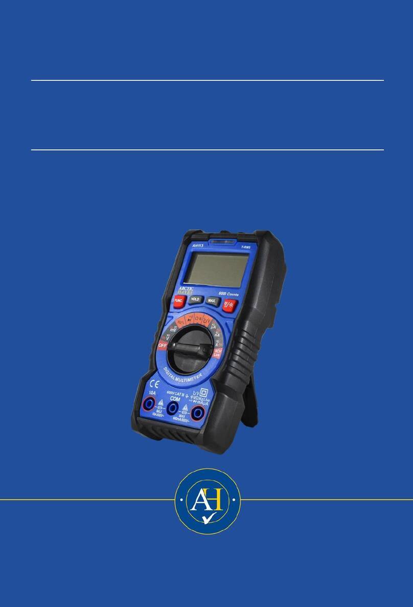
ARCTIC HAYES AH113 user manual
