PDi 879RMS User manual
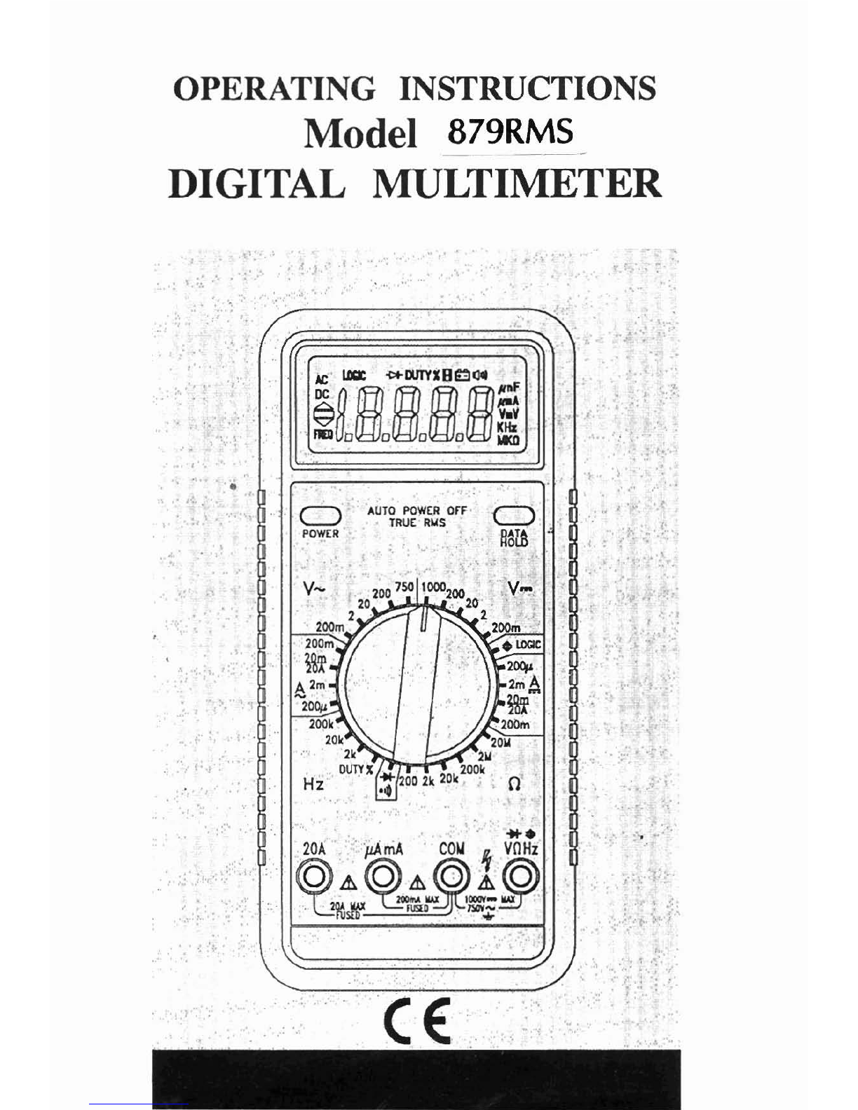
OPERATING INSTRUCTIONS
Model
879RMS
DIGITAL
MULTIMETER
CONTENTS
HOW TO
MAKE MEASUREMENTS
..................................
&
voltage Measurements
8
CurrentMeasurements
9
ResistanceMeasurements 11
Continuity
the ti^^
I1
DiodeTesting 11
LogicTesting 11
Frequency and DutyCycleMeasurements 12
INTRODUCTION
Thismanualcontainsinformationand warningswhich mustbe followed
to ensure safe operation and retain the meter in safe condition.
WARNING
READ "SAFETY INFORMATION" BEFORE USING THE METER.
Thismultimeter isahandheld, 20000-count instrument that isdesigned
for use in the laboratory, field servicing, and at home. This meter
featurescompactdesignwith roundedcorners foreasyhandling and has
arugged case in shock resistant and fire-retardant. Electronicoverload
protection forall functionsand ranges. TheProtective Holster (optional
accessory) combined with rugged case make it a durable and reliable
instrument.
UNPACKING
AND
INSPECTION
Upon removingyournew Digital Multimeter(DMM) from itspacking,
you should have the following items:
1. Digital Multimeter
I
2.
Test Lead Set (one black, one red)
3.
9-Volt Battery (installed in meter)
i
4.
Instruction Manual
5.
One SpareFuse (500mA/600V, 6.3mm
x
25mm, fast acting)
If any of the above items are missing or are received in a damaged
cond~tion,pleasecontact thedistributor from whom you purchased the
unit.

SAFETY INFORMATION
Injury or death can occur even with low voltages and low currents. It
is extremely important that you read these safety information before
usingyourmultimeter. Followall safety practicesand properoperating
procedures for equipment being tested.
I. Exercise extreme caution when:
Measuring voltage above 20 volts, measuring current greater
than
IOmA, measuring AC power line with inductive loads, measuring
AC power line during electrical storms.
2.
Always inspect your DMM, test leads and accessories for
any
sign
of damage or abnormality before every use. If any abnormal
conditions exist (i.e., broken ordamaged test leads, cracked case,
display not reading, etc.),donot attempt to takeany measurements.
3.
Never ground yourselfwhen taking electrical measurements. Donot
touch exposed metal pipes, outlets, fixtures, etc., which might beat
groundpotential. Keepyourbody isolated from groundbyusing dry
clothing, rubber shoes, rubber mats, or any approved insulating
material.
4.
Never touch exposed wiring, connections,testprobetips, orany live
circuit conductors when attempting to make measurements.
5. Never replace the protective fuse insidethe DMM with a fuseother
than the specified or approved equal fuse.
6.
Do not operate this instrument in an explosive atmosphere (i.e., in
the presence of flammable gases or fumes, vapor or dust.)
7.
Measuring voltage which exceeds the limits
of
the multimetermay
damagethe meter and exposetheoperatortoashockhazard. Always
recognizethemeter voltage limits asstated onthefrontofthe meter.
8.
Never apply more than 5OOVDC between the COMjack and earth
ground.
9.
Never touch a voltage source when the test leads are plugged into
a current jack.
10. When testing for the presenceof voltage orcurrent, make surethe
voltage orcurrent ranges arefunctioningcorrectly. Takea reading
of a known voltage or current before assuming a zero reading
indicates no current or voltage.
SYMBOL
EXPLANATION
1-
-
-
-
,
,
,
l(1))
A
Attention! Refer to the Operating Instructions
Dangerous Voltage May Be Present at terminals
Ground
AC
-
Alternating Current
DC
-
Direct Current
Audible Continuity
/
Diode
Logic Test
Double Insulation
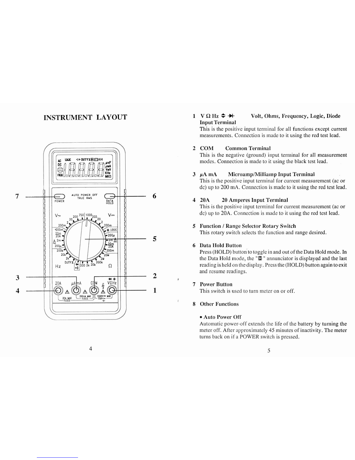
INSTRUMENT
LAYOUT
1 VQHz=-H
Volt, Ohms, Frequency, Logic, Diode
InputTerminal
This is the positive input terminal for all functions except current
measurements. Connection is made to it using the red test lead.
2
COM Common Terminal
This is the negative (ground) input terminal for all measurement
modes. Connection is made to it using the black test lead.
3
pA niA MicroamplMilliamp Input Terminal
This is the positive input terminal for current measurement (ac or
dc) up to
200
mA. Connection is made to it using the red test lead.
6
4
20A
20
Amperes Input Terminal
This is the positive input terminal for current measurement (ac
or
dc) up to 20A. Connection is made to it using the red test lead.
5
Function
I
Range Selector Rotary Switch
This rotary switch selects the function and range desired.
5
6
Data Hold Button
Press (HOLD)buttonto toggle in and out of the Data Hold mode. In
the Data Hold mode, the
"
13
"
annunciator is displayed and the last
readingisheld on thedisplay. Press the (HOLD) button again toexit
and resume readings.
3
A
I
7
Power Button
1
This switch is used to turn meter on or off.
8
Other Functions
Auto Power Off
Automatic power-off extends the life of the battery by turning the
meter off. After approximately
45
minutes of inactivity. Themeter
turns back on if a POWER switch is pressed.

Input Warning Beeper
The Input Warning Beeper is a feature to protect the meter and you
from unintentional misuse. If the DMM is set to measure a voltage
whilethe test leadsareplugged into acurrentjack, very high current
could resultwhen thetest lead tips areplaced tothevoltagetest point.
This feature warns you that the test lead needs to be changed from
a currentjack to the voltage jack.
All currentranges arefusedwith fastacting ceramicfuses
as
an
added
protection.
TrueRMS Measurements
This multimeter permits direct measurement of the true RMS value
of a signal. This is the best way to measure parameters used for
measuremen!s relating to power.
The relationship between the total true RMS (AC
+
DC) and
the
componentAC and DC signals is givenby thefollowingexpression:
True RMS
=
d
(AC RMS Comp~nent)~
+
(DC Comp~nent)~
RMS
is
equivalent tothatDC valuewhichdissipates thesameamount
of power in a resistor asthe original signal and can be visualized by
the relationships
Power
=
"Average-responding" meters provide accurate RMS readings for
sinusoidal signals,but can introducesignificant errorswhen measur-
ing nonsinusoidal waveforms. Thefollowing tableshowstheerrors
that result when the average-respondingmeasurement isused instead
of the True RMS value.
Thisnii~ltimeteris ACCorlpledand will accurately measuretheAC RMS
component ofan inputsignal. TheDC voltage function willmeasurethe
DC component. Toobtain the total true RMS value, measure theRMS
AC component on the AC function and the DC component on the DC
function. Then,calculate the TrueRMS value, using the measured AC
and DC components and the True RMS expression given above.
Power Calculations (watts) from Voltage Measurements
(Vpk
=
IOOV, Load
=
1
kRresistor)
AC converters of all types are limited by their frequency response and
input dynamicrange. Measurementsof complex waveforms will notbe
affected by converterbandwidth limitations, provide that all significant
AC components contained within the waveforms are within the band-
width of the converter.
Crest factor isameasure of the input dynamicrangeofanACconverter.
It expresses the ability of the converter to accept a signal that has large
peak values compared to itsRMS valuewithout saturating theconverter
circuitry and degrading the specified accuracy. Crest factor is defined
as the ratio of the peak voltage to the total AC RMS voltage.
Sinewave
Square wave
Triangle wave
Crest Factor
=
V(PEAK)
V(AC RMS)
AC RMS
average
responding
5.0
12.3
3.1
--
AC
True RMS
5.0
10.0
3.3
Error
0%
+23
%
-6
%

HOW
TO'
MAKE
MEASUREMENTS
Before making any measurements always examine the instrument
and accessoriesused with theinstrumentfordamage, contamination
(excessivedirt,grease, ect.) and defects. Examine the test leads for
cracked orfrayed insulation and make surethe lead plugs fit snugly
into the instrumentjacks. If any abnormal conditions exist do not
attempt to make any measurements.
VOLTAGE RlEASUREMENTS
1. Insert the black and red test leads into the COM and V-R input
terminals respectively.
2. Select the desired AC voltage range (V-
),
or DC voltage range
(V-).
WARNING
To avoid possible electric shock, instrument damage and
/
or
equipment damage,donot attempt totakeany voltagemeasurements
if the voltageis above
1
OOOVdc
/
750Vac. lOOOVdc
and
750Vacare
the maximum voltages that this instrument is designed to measure.
The"COM"terminal potential shouldnot,exceed500Vmeasured to
ground.
A
3.
Connect thetest lead tips in parallel with the circuit to bemeasured
(e.g. across a load or power supply). Be careful not to touch any
energised conductors. Note the reading.
4.
When allmeasurements arecompleted, disconnectthe test leadsfrom
the circuit under test. Remove test leads from the multimeter.
For
DC
voltage readings, the RED lead tip should beconnected to
the positiveside of thecircuit, the BLACK leadto thenegativeside.
A minussign on the left hand sideof theLCDwill appear if theleads
areconnected the other way round.
CURRENT MEASUREMENTS
These are made in series with the test circuit. All the current to be
measured flows through the multimeter.
WARNING
Donot attempt to measurecurrents inhigh energy circuitscapable
of delivering greater than 600V. Since the fuse is rated at 600V
damageor injurycould occur. The20Ainput terminal isprotected
by a20AI600Vhigh energy,fastblow fuse. The
mA
input terminal
is protected by a 500mAl600V fast blow fuse.
Do not exceed the limits of each current input terminal. This is 20A
(maximum time limit of 30seconds for currents greater than 10A)for
the 20A terminal and 200mA for the mA terminal.
All current ranges are fused. If a current greater than 20A on the 20A
rangeorgreater than500mA onall otherranges flows, thefusewillblow
causing an open circuit between the current measuring terminals.
1. Insert the BLACK test lead in the COM input terminal.
2. Formeasuring currents less than 200mA, connect the REDtest lead
to the mA input terminal. For measuring currents between
200mA
and 20A connect the RED test lead to the 20A terminal.
3.
Select the desired AC current range or DC current range.
4.
Switch OFFordisconnectthe circuitto bemeasured from all power
:
sources,connect themultimeter in serieswith theconductorin which
the current to be measured flows.
5. Switch ON the circuit. Note the reading.
6. Switch OFFordisconnect the circuitand removethetest leads from
multimeter.

CAUTION
A common abuse of multimeters is to attempt to measure a voltage
while the test leads arestill plugged into the current input terminals.
This basically puts a short circuit across the voltage source since
current ranges have a low impedance. If the voltage source is
typically
240VAC
ora3-phase industrial voltage
(415V),
very high
fault currents can result. This is why all current input terminal are
fused.
If
the fusesblow they mustonly bereplaced by theequivalent
ones otherwise the safety of the instrument may be impaired.
7.
Never apply a voltage between the COM terminal and current
terminals.
8.
When switching between current ranges to obtain greater accuracy
and better resolution, completely de-energise the circuit to be
measured before changing the range.
RESISTANCE MEASUREMENTS
Turnoffpoweronthetest circuitanddischargeall capacitors before
attempting in-circuit iesistancemeasurements. If an external volt-
age is present across a component, it will be impossible to take an
1.
Insert the BLACK and RED test leads into the COM and
VQ
input
terminals respectively.
2.
Select the desired ohms
(R)
range.
3. Connectthe BLACK and RED test probe tips to the circuitordevice
under test, making sure it is de-energised first.
4.
Test lead resistance can interfere when measuring low resistance
readingsand should be subtracted from resistance measurements for
accuracy. Select lowest resistance range andmakethe testleadsshort
together.Thedisplay value is thetest lead resistancetobesubtracted.
CONTINUITY TESTING
1. Select the
(
10))
)
position by turning the rotary selector switch.
2.
Follow steps
1
and 3 as for resistance measurements.
An audible tone will sound for resistance less than approximately
150Q.
After all measurements are completed, disconnect the test
leads from the circuit and from the multimeter input terminals.
'I
I
DIODE TESTING
CAUTION
Measurements must only be made with the circuit power OFF.
1. Set the rotary selector switch to the
(*)
position.
2.
Follow steps
1
and 3 as for resistance measurements.
3.
TheRED lead should be connected totheanodeand theBLACK lead
to the cathode. The typical forward voltage drop should be about
0.7V
for silicon diode or
0.4V
for germanium diode.
4.
If the diode is reverse biased or there is an open circuit the reading
display shows
"1
".
LOGIC TESTING
1.
Insert the BLACK and RED test leads into the "COM" and
"VR"
input terminals respectively.
1
2.
Select the logic function by rotating the selector dial to the
(
*
)
logic position.
\
3. Connect the BLACK probe tip to the Common Bus of the logic
circuitry to be measured.
4.
Connect the RED probe tip to the point to be tested.
5.
With a logichigh pulse
(I),
the
A
indicatorwilldisplay in the LCD
and a beeping sound will emit. With a logic low pulse
(O),
the
r
indicator will appear in the LCD.
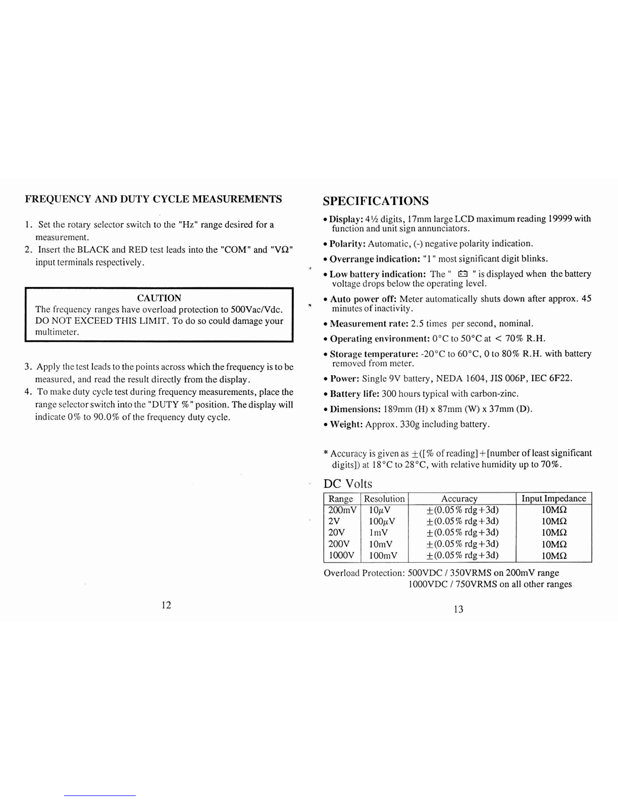
FREQUENCY AND DUTY CYCLE MEASUREMENTS
SPECIFICATIONS
1.
Set the rotary selector switch to the "Hz" range desired for a Display:
4%
digits, 17mmlarge LCD maximum reading 19999with
function and unit sign annunciators.
-
measurement. Polarity: Automatic,
(-)
negative polarity indication.
2. Insert the BLACK and RED test leads into the "COM" and "VQ"
input terminals respectively. Overrange indication:
"
1
"
most significantdigit blinks.
The frequency ranges have overload protection to 500Vac/Vdc.
DO NOT EXCEED THIS LIMIT. To do so could damageyour
multimeter.
Low battery indication: The
"
El
"
is displayed when thebattery
voltage drops below the operating level.
Auto power off: Meter automatically shuts down after approx. 45
minutes of inactivity.
Measurement rate: 2.5 times per second, nominal.
Operating environment: 0°Cto 50°Cat
<
70%R.H.
Storage temperature: -20°C to 60°C, 0 to 80%R.H. with battery
3. Apply thetest leads to thepoints acrosswhich thefrequency is tobe removed from meter.
measured, and read the result directly from the display. Power: Single9V battery, NEDA 1604,JIS 006P, IEC 6F22.
4. To make duty cycle test during frequency measurements, place the Battery life: 300 hours typical with carbon-zinc.
range selectorswitch into the "DUTY
%"
position. Thedisplay will
.
Dimensions:
Sgmm
87mm
(W)
37mm
indicate 0%to 90.0% of the frequency duty cycle. Weight: Approx. 330g including battery.
*
Accuracy is given as
*([%
of reading] +[number of least significant
digits]) at 18°Cto 2S°C, with relative humidity up to 70%.
DC
Volts
Accuracy Input Impedance
200mV lOpV k(0.05
%
rdg+3d)
k(0.05
%
rdg+3d)
+(0.05
%
rdg+3d)
200V lOmV
f
(0.05%rdg+3d) 1OMR
l00OV lOOmV +(0.05% rdg+3d) lOMQ
Overload Protection: 500VDC
/
350VRMS on 200mV range
1
OOOVDC
/
750VRMS on all other ranges

AC Volts
(True RMS)
Range
I
Resolution I~ccurac~(50~zto 500~z)l500Hz to 2KHz
2OOmVI 10pV
I
+(1.0% rdg+lOd)
1
+(2.0% rdg+20d)
Input Impedance: IOMQ
Overload Protection: SOOVDC
/
350VRMS on 200mV range
IOOOVDC
/
750VRMS on all other ranges
2V
20V
200V
750V
DC Current
Range
I
F&solution
I
Accuracy
I
Voltage Burden
200pA
I
lOnA
I
&(0.5%rdg+5d)
I
300mV
100pV
1
mV
lOmV
lO01nV
Overload Protection: 500mAJ600V fuse on mA inputs (fast blow
ceramic fuse). 20A1600V fuseon 20A inputs(fast blow ceramic fuse).
**
20A for 30 seconds maximum.
*(I .O%rdg+ 10d)
+(I .O%rdg+ l0d)
-
+(1.0% rdg+ 1Od)
+(2.0%rdg+20d)
2mA
201nA
200mA
20.4
*
x
AC C~rrent
(True RMS)
+(2.0% rdg+20d)
+(2.0% rdg+20d)
+(2.0% rdg+20d)
Unspecified
+(0.8% rdg+ 10d)
1
OOnA +(0.8%rdg+10d) 300mV
*(0.8% rdgf 1Od) 300mV
&(0.8% rdg+lOd) 600mV
1mA +(2.5% rdg+ 10d) 800mV
lOOnA
I
PA
10pA
I
mA
Resistance
*(0.5% rdg+Sd)
k(0.5%rdg+5d)
k(0.5%rdg+5d)
+(2.0%rdg+ 10d)
.
Overload Protection: 500V DC or RMS AC
300mV
300mV
600mV
800mV
Continuity Test
Open Circuit Volts
=3.3Vdc
23.3Vdc
=3.3Vdc
-3.3Vdc
e3.3Vdc
=3.3Vdc
Range
200Q
2kR
20kR
200kR
2MQ
20MQ
Range l~udibleThreshold
I
Response Time
I
Open Circuit Volts
2V
(
Less than l5OR
I
Approx. 500ms
I
3.3Vdc typical
p~
Overload Protection: 500V DC or RMS AC
Diode Test
Resolution
lOmQ
0.IQ
1Q
10Q
1
OOQ
1kQ
Accuracy
+(0.25% rdgf10d)
k(0.15
%
rdg+3d)
+(0.15% rdg+3d)
+(0.15%rdg+3d)
f
(0.25%rdg+lOd)
+(I .O%rdg+10d)
Overload Protection: 500V DC or RMS AC
Logic Test
Open
Circuit Volts
3.3Vdc typical
Range
2V
Test Voltage: 5VDC
Duty Cycle: >20% and <SO%
Overload Protection: 500mAl600V fuse on mA inputs (fast blow Frequency Response: 20MHz
ceramic fuse). 20A1600V fuseon 20A inputs(fast blow ceramic fuse). Indication: 40msec beep at logic
1
(Hi)
**
20A for 30 seconds maxi~nurn. Overload Protection: 5OOVDC or RMS AC
Resolution
Pluse Width
(min.)
25nS
Thresholds
Logic
1
(Hi)
I
Logic 0 (Lo)
2.8Vf 0.8V
I
0.8V+0.5V
Accuracy
Pulse Rise
(max.)
l0,uSec
Test
Current
O.lmV
1
+(0.5%
rdg+ld)
Pulse Rep
(max.)
lMpps
l.OmA

Frequency
Accuracy Input Impedance
0.1Hz +(0.5% rdg+3d) 1OMWlOpF
+(0.5% rdg+3d) 1OMWlOpF
+(0.5% rdg+3d)
1
OMMlOpF
Sensitivity: 50mV RMS min. (Sine Wave)
400mV RMS min. at >30% and <70% duty cycle
Effect reading: More than 10Hzat pulse width >2pSec
Overload protection: 5OOVDC or RMS AC
Duty
Cycle
Frequency range: 20Hz to 20kHz
Overload protection: 5OOVDC or RMS AC
Range
0 to 90.0%
MAINTENANCE
Repairs or servicing not covered in this manual should only be
performed by qualified personnel.
Resolution
0.1
%
REPLACING
THE
BATTERY
TOAVOID ELECTRICALSHOCK, DISCONNECT THETEST
LEADS AND ANY INPUT SIGNALS BEFORE REPLACING
THE BATTERY. REPLACE ONLY
WITH
SAME TYPE OF
BATTERY.
PulseWidth
>
I
OpSec This meter is powered by a NEDA type 1604 or equivalent 9-volt
battery.
When the multimeter displays the
"
E3
"
the battery must be replaced
to maintain properoperation. Use the following procedureto replacing
the battery:
Accuracy
(5V
Logic)
,(2.0% rdg
+
10d)
1. Disconnect test leads from any live source, turn the rotary switch to
OFF,
and remove the test leads from the input terminals.
2. Thecase bottom is secured to the case top by three screws and two
internal snaps (at the LCD end). Using aPhillips-head screwdriver,
removethe threescrewsfrom thecasebottom and turn thecase over.
3.
Lift the input terminal end of thecase bottom until it gentlyunsnaps
from the case top at the end nearest the LCD.
4.
Remove battery and replace with a new equivalent 9-volt battery.
5. Replace the casebottom, ensuring that the two snaps on the casetop
(at the end near the LCD) are engaged. Reinstall the three screws.

REPLACING
THE
FUSE
NOTE
WARNING
TOAVOID ELECTRICAL SHOCK, DISCONNECT THETEST
LEADS AND ANY INPUT SIGNALS BEFORE REPLACING
THEFUSES. REPLACEONLY WITHSAMETYPEOFFUSES.
THE
20A
INPUTTERMINALISPROTECTED
BY
A
F20A,600V
HIGH ENERGY, FAST ACTING. THE mA INPUTTERMINAL
IS PROTECTED BY
A F500mA,600V
FAST ACTING FUSE.
-
Use the following procedure to examine or replace the meter's fuses:
1.
Disconnect test leads from any live source, turn the rotary switch to
OFF, and remove the test leads from the input terminals.
2.
The case bottom is secured to the case top by three screws and two
internal snaps (at the LCDend). Using aPhillips-head screwdriver,
remove thethreescrewsfrom thecasebottom and turn thecaseover.
3.
Lift the input terminal end of the case bottom until itgently unsnaps
from the case top at the end nearest the LCD.
4.
Remove blown fuse, replace with fuse of the same size and rating.
Make sure the new fuse is centered in the fuse holder.
5.
Replace the case bottom, ensuring that the two snapson the casetop
(at the end near the LCD) are engaged. Reinstall the three screws.

PIN
7000-
1328
March
1994
Table of contents
Other PDi Multimeter manuals


