PEACOCK FINCH E26 User manual

Before you begin, read these instructions completely and carefully.
• Be certain electrical power is OFF before and during installation, maintenance and removal.
• Fan wiring must be properly grounded in accordance with the NEC and any applicable local code requirements.
• Use only UL or IEC approved wire for input/output connections.
• Verify that supply voltage matches voltage on fan label. Installation to any other connection may void the warranty.
• Wear gloves during installation to prevent injury and do not expose wiring to metal or sharp edges.
IMPORTANT SAFETY PRECAUTIONS
WARNING: To reduce the risk of fire, electrical shock, or personal injury, mount this fan to an outlet box marked "Acceptable for Fan Support of
22.7kg (50lbs)" or less and use Mounting Screws provided with the outlet box. CAUTION: Install the primary mounting means and use only the
hardware provided with the fan.
To reduce the risk of personal injury, do not bend the blade brackets when installing the brackets, balancing the blades or clearing the fan. Be
careful not to insert foreign objects in between rotating fan blades.
To reduce the risk of fire or electrical shock, do not use this fan with any solid-state speed control device.
The important safeguards and instructions appearing in this manual are not meant to cover all possible conditions and situations that may occur.
It must be understood that common sense, caution and careful attention to detail are factors which cannot be built into this product. These
factors must be supplied by the person or persons installing, caring for, and operating the unit.
This product should be installed, inspected and maintained by a qualified and licensed electrician. Installation of luminaire must be in accordance
with NEC and local code requirements.
ELECTRIC SHOCK FALLING PARTS
ABRASIONS BURNS
FINCH CEILING FAN E26
Installation Manual
REV 2022 1027
SPECIFICATIONS AND DETAILS ARE SUBJECT TO CHANGE WITHOUT NOTIFICATION. CONTACT PEACOCK FAN COMPANY FOR UP TO DATE DETAILS.
PEACOCK FAN COMPANY • PEACOCKFAN.COM
SAVE THESE INSTRUCTIONS 1

FINCH CEILING FAN E26
Installation Manual
REV 2022 1027
SPECIFICATIONS AND DETAILS ARE SUBJECT TO CHANGE WITHOUT NOTIFICATION. CONTACT PEACOCK FAN COMPANY FOR UP TO DATE DETAILS.
PEACOCK FAN COMPANY • PEACOCKFAN.COM
SAVE THESE INSTRUCTIONS 2
DIMENSIONS
PRODUCT PARTS
Mounting Bracket
Support Rod
Retaining Clip and Washer
Canopy
Coupler Cover
Yoke Screws
Top Plate
Blade Screws and Washers
Reverse Switch
Three Speed Switch (Pull Chain)
Glass Shade
Safety Pin
Center Band
Light Switch (Pull Chain)
11.8”
52”
17.3”
5”
2”
FINCH CEILING FAN E26
Installation Manual
REV 2022 1027
SPECIFICATIONS AND DETAILS ARE SUBJECT TO CHANGE WITHOUT NOTIFICATION. CONTACT PEACOCK FAN COMPANY FOR UP TO DATE DETAILS.
PEACOCK FAN COMPANY • PEACOCKFAN.COM
SAVE THESE INSTRUCTIONS 3
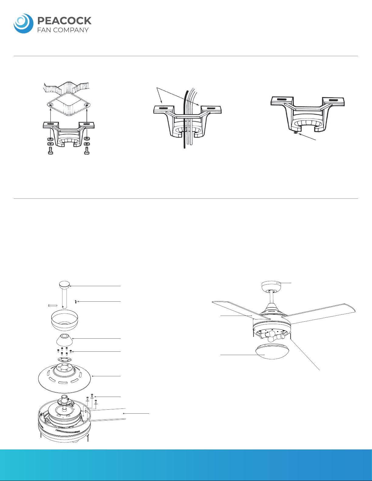
MOUNTING BRACKET INSTALLATION
A) Secure the mounting bracket onto the electrical
junction box using two screws, two washers and two
lock washers.
B) The mounting bracket has slotted holes to enable
it to move sideways for proper alignment. Make sure
the mounting bracket is centered over the electrical
junction box and that it is securely attached.
C) Loosen the two canopy mounting screws on the
underside of the mounting bracket halfway. This will
allow for easier installation of the ceiling canopy.
Junction Box
Slotted Holes
Ceiling Canopy
Mounting Screws
NO MOVEMENT SHOULD OCCUR BETWEEN THE
MOUNTING BRACKET AND THE ELECTRICAL
JUNCTION BOX.
Pull the electrical wires in the junction box down and
through the mounting bracket.
LAMP & GLASS SHADE INSTALLATION
A) Remove six screws from yoke cover and set yoke cover aside. Remove three screws from the top plate (located on the motor yoke). Set top plate aside. Locate blade
attachment screws and washers. Tighten securely with a Phillips screwdriver. Repeat for the remaining blades.
B) Reattach plate to motor yoke and align the key slot holes on the motor yoke. Secure plate to motor yoke using previously removed screws.
C) Loosen the set screws (2) in the support rod coupler until the inside of the channel is clear of the screw tip.
D) Remove and save the safety pin and washer at the end of the support rod.
E) Slide the ceiling canopy onto the support rod, followed by the support rod coupler cover.
F) Feed the electrical wires from the fan housing through the support rod.
G) Thread the support rod into the coupler until the safety pin can be inserted through the hole in both the rod and coupler.
H) Insert the safety pin through the hole in the support rod coupler and support rod then attach washer into safety pin and the retaining clip on the other side.
I) Tighten both set screws and safety screw on the support rod coupler.
J) Place lamp into the socket on the light kit, then place glass shade onto the light kit and rotate until secure.
Support Rod
Safety Pin
Coupler Cover
Yoke Screws
Top Plate
Blade Screws and Washers
Fan Blade
Center Band
Center Band
Glass Shade
Three Speed Switch
(Pull Chain - If Applicable)

FINCH CEILING FAN E26
Installation Manual
REV 2022 1027
SPECIFICATIONS AND DETAILS ARE SUBJECT TO CHANGE WITHOUT NOTIFICATION. CONTACT PEACOCK FAN COMPANY FOR UP TO DATE DETAILS.
PEACOCK FAN COMPANY • PEACOCKFAN.COM
SAVE THESE INSTRUCTIONS 4
FAN BODY INSTALLATION
A) Notice the ball hanger on the end of the support
rod is grooved on one side. This keyway fits over
the small keyway pin on the inside of the mounting
bracket and prevents the ceiling fan from spinning
on the mounting bracket.
B) Lift the fan and place the ball hanger in the center
of the mounting bracket with the keyway pin inserted
into the keyway on the ball hanger. Turn the fan left
and right slightly to make sure it is securely aligned on
the bracket with the keyway pin in the keyway.
C) Trim the lead wires, leaving about six inches of each
wire extending from the support rod.
Mounting Bracket
Keyway Pin
Ball Hanger
Support Rod
Keyway Pin
Mounting
Bracket
Ball Hanger
Support Rod
Ground
Wire
Support Rod
Ball Hanger
ELECTRICAL CONNECTIONS
A) Attach the GREEN wire (connected to the ball hanger) to the GROUND wire in
the junction box. The GROUND wire is a bare copper wire without plastic insulation.
Attach the BLACK wire and BLUE wire from the ceiling fan to the BLACK wire in the
junction box. Attach the WHITE wire from the ceiling fan to the WHITE wire in the
junction box.
B) Place the connected wires inside the electrical junction box with the BLACK and
BLUE wires to one side and the WHITE and GREEN to the other side. Make sure the
wire nuts do not come loose during installation.
Black
Blue
Green
White
Black
Blue
White
Green
ELECTRICAL CONNECTIONS (WALL SWITCH)
WARNING: Turn OFF the electric power at the main fuse or circuit breaker box before wiring.
The installation of this product must be carried out by a qualified licensed electrician.
• This fan is equipped with a wall control unit controlling the fan speeds and light kit.
• Make the following wire connections by using the wire nuts supplied.
• Set the knob and light switch of the wall-mounted control in the off (0) position.
• Connect the wires as shown below:
1) To the wall control
A) Connect the Black wire from fan motor to the wall control Black wire (marked with “TO
MOTOR L”)
B) Connect the Blue wire from fan motor to the wall control Blue wire (marked with “FOR
LIGHT L”)
2) To the household supply wires:
A) Connect the Black wire (marked with “AC in L”) from wall control to the Live wire (Black)
from supply circuit on the wall outlet box.
B) Connect the White wire from fan motor to the Neutral wire (White) from supply circuit on
the wall outlet box.
C) Connect the three Green (Ground) wires from fan downrod, mounting bracket and wall
control to the Ground wire from supply circuit on the wall outlet box.
• After making the wire connections,ensure the wires should be spread apart with the
grounded conductor and the equipment-grounding conductor on one side of the outlet box
and the unground conductor on the other side of the outlet box.
• Ensure the splices after being made should be turned toward and pushed carefully into the
outlet box.
• Make sure no bare wire is visible at the wire nuts.
120V AC / 60 Hz
Supply Circuit
GROUND
Ground
Wall
Control
White
Black
Blue
Green
Green
Ground To Downrod
Ground To Mounting Bracket
BLACK L
AC in L (Black)
To Motor L (Black)
For Light L (Blue)
Ground
Ground (Green)
To Light L (Blue)
To Motor L (Black)
WHITE N
White N
White N
Wall
Outlet
Box
Ceiling
Outlet
Box
Other PEACOCK Fan manuals


Popular Fan manuals by other brands

ELTA FANS
ELTA FANS H03VV-F installation guide

Hunter
Hunter 20714 Owner's guide and installation manual

Emerson
Emerson CARRERA VERANDA CF542ORB00 owner's manual

Hunter
Hunter Caraway Owner's guide and installation manual

Panasonic
Panasonic FV-15NLFS1 Service manual

Kompernass
Kompernass KH 1150 operating instructions


