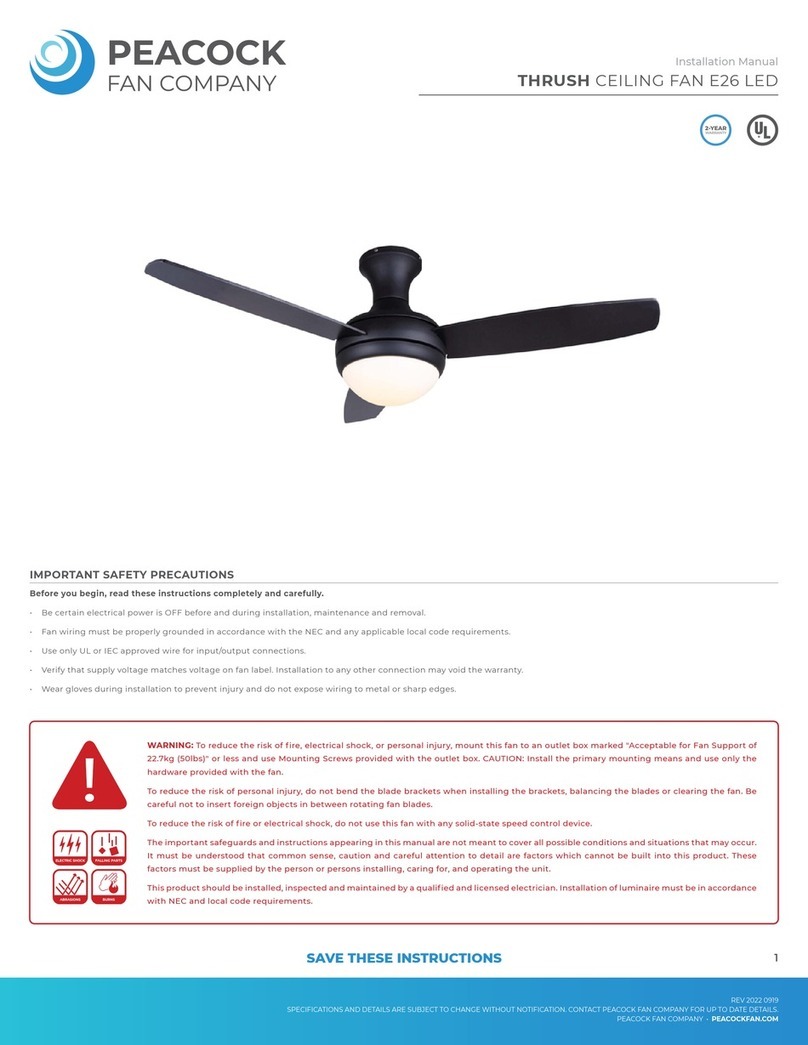
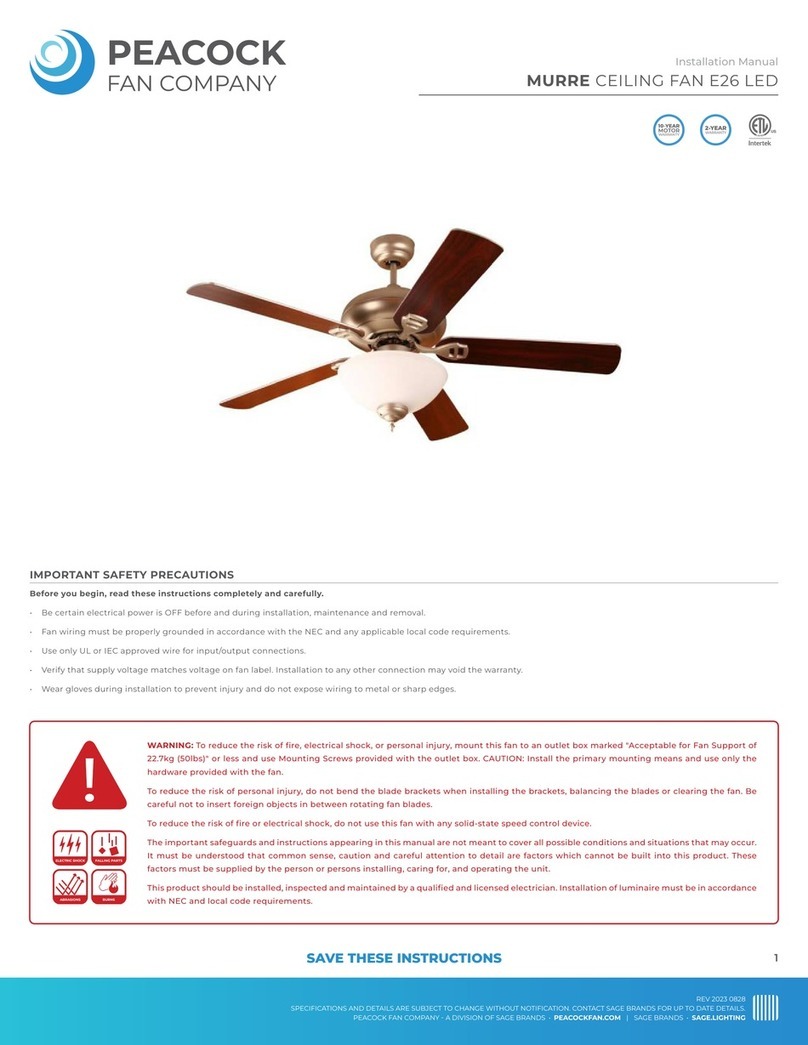
PEACOCK KITE User manual

Before you begin, read these instructions completely and carefully.
• Be certain electrical power is OFF before and during installation, maintenance and removal.
• Fan wiring must be properly grounded in accordance with the NEC and any applicable local code requirements.
• Use only UL or IEC approved wire for input/output connections.
• Verify that supply voltage matches voltage on fan label. Installation to any other connection may void the warranty.
• Wear gloves during installation to prevent injury and do not expose wiring to metal or sharp edges.
IMPORTANT SAFETY PRECAUTIONS
WARNING: To reduce the risk of fire, electrical shock, or personal injury, mount this fan to an outlet box marked "Acceptable for Fan Support of
22.7kg (50lbs)" or less and use Mounting Screws provided with the outlet box. CAUTION: Install the primary mounting means and use only the
hardware provided with the fan.
To reduce the risk of personal injury, do not bend the blade brackets when installing the brackets, balancing the blades or clearing the fan. Be
careful not to insert foreign objects in between rotating fan blades.
To reduce the risk of fire or electrical shock, do not use this fan with any solid-state speed control device.
The important safeguards and instructions appearing in this manual are not meant to cover all possible conditions and situations that may occur.
It must be understood that common sense, caution and careful attention to detail are factors which cannot be built into this product. These
factors must be supplied by the person or persons installing, caring for, and operating the unit.
This product should be installed, inspected and maintained by a qualified and licensed electrician. Installation of luminaire must be in accordance
with NEC and local code requirements.
ELECTRIC SHOCK FALLING PARTS
ABRASIONS BURNS
KITE CEILING FAN LED
Installation Manual
REV 2023 0511
SPECIFICATIONS AND DETAILS ARE SUBJECT TO CHANGE WITHOUT NOTIFICATION. CONTACT PEACOCK FAN COMPANY FOR UP TO DATE DETAILS.
PEACOCK FAN COMPANY • PEACOCKFAN.COM
SAVE THESE INSTRUCTIONS 1

KITE CEILING FAN LED
Installation Manual
REV 2023 0511
SPECIFICATIONS AND DETAILS ARE SUBJECT TO CHANGE WITHOUT NOTIFICATION. CONTACT PEACOCK FAN COMPANY FOR UP TO DATE DETAILS.
PEACOCK FAN COMPANY • PEACOCKFAN.COM
SAVE THESE INSTRUCTIONS 2
PRODUCT PARTS
Mounting Bracket
Downrod
Safety Clip
Canopy
Joint Cover
Motor Housing
Joint Screws
Motor Joints
Blade Arm Screws
Blade Arm
Fan Blade
Light Switch
Blade Arm Nuts
Light Kit
Integrated LED
Lamp Shade
Motor
Fan Switch
Switch Box
Safety Pin
TOOLS & MATERIALS REQUIRED
Phillips
Screwdriver
Flathead
Screwdriver
Wrench
Step Ladder
Wire Cutter
PACKAGE CONTENTS
Mounting Bracket (1)
Downrod (1)
Safety Clip and Pin
Canopy (1)
Joint Cover (1)
Motor Assembly (1)
Blade Arm (3)
Fan Blade (3)
Light Kit (1)

KITE CEILING FAN LED
Installation Manual
REV 2023 0511
SPECIFICATIONS AND DETAILS ARE SUBJECT TO CHANGE WITHOUT NOTIFICATION. CONTACT PEACOCK FAN COMPANY FOR UP TO DATE DETAILS.
PEACOCK FAN COMPANY • PEACOCKFAN.COM
SAVE THESE INSTRUCTIONS 3
MOUNTING OPTIONS
If there isn't an existing UL Listed mounting box,
disconnect the power by removing fuses or turning off
circuit breakers.
Secure the junction box directly to the building
structure. Use appropriate fasteners and building
materials. The junction box and its support must be
able to fully support the moving weight of the fan (at
least 50 lbs.). Do not use plastic junction boxes.
Figure 1 and 2 are examples of different ways to mount
the junction box.
Figure 3 is an example of a installation on a steep
sloped ceiling. You may need a longer downrod to
maintain a proper blade clearance when install on a
slope.
To hang your fan where there is an existing fixture but
no ceiling joist, you may need an installation hanger
bar approved for the ceiling fan support as shown in
Figure 4.
INSTALLING THE MOUNTING BRACKET
A) Remove the canopy from the mounting bracket
buy loosening the 2 set screws on the downside face
of the mounting bracket. Set canopy aside.
B) Attach the mounting bracket to the junction box
using 2 screws and 2 washers provide (figure 5).
C) For best performance, be sure the mounting brack-
et is level and secured firmly against the ceiling. You
may need to insert additional washers (not included)
between the junction box and mounting bracket to
make it level.
FIGURE 1
FIGURE 3
FIGURE 5
FIGURE 4
FIGURE 2
Junction Box
Junction Box
Aligned ceiling
maximum 25°
Recessed
Junction
Box
Provide
Strong
Support
Ceiling
Mounting
Bracket Junction Box
Junction Box

KITE CEILING FAN LED
Installation Manual
REV 2023 0511
SPECIFICATIONS AND DETAILS ARE SUBJECT TO CHANGE WITHOUT NOTIFICATION. CONTACT PEACOCK FAN COMPANY FOR UP TO DATE DETAILS.
PEACOCK FAN COMPANY • PEACOCKFAN.COM
SAVE THESE INSTRUCTIONS 4
FAN ASSEMBLY
HANGING THE FAN
A) Align the screw holes in blade arm with fan blade.
Locate blade screws and nuts. Fasten with 3 sets for
each blade. Make sure the nuts are facing down and
screws facing up. Repeat for the remaining blades.
(Figure 6)
B) Rotate the motor so a screw hole can be seen
through the opening in the switch box. Place the
blade arm between the motor and switch box. Align
the holes in blade arm and motor. Secure with 2 motor
screws for each blade arm. Rotate the motor and
repeat for the remaining blade arms. (Figure 7)
C) Loosen and save the 3 screws on the switch box.
Locate light kit. Connect wire sockets from light kit
and motor. Place light kit onto switch box. Align slots
in light kit with switches on switch box. Secure with 3
screws loosened previously. (Figure 8)
D) Loosen joint screw halfway to clear the way for
downrod. Take out and save the safety pin on the
downrod. Place the canopy and then joint cover onto
the downrod. Thread power wires from the motor
through the downrod. Insert downrod into the motor
joint. Align holes and insert safety pin and clip. Fasten
the joint screw. (Figure 9)
A) Insert the support rod in the side of the mounting
bracket. Notice the ball hanger is grooved on one side
(figure 10). This keyway fits over the small keyway pin
on the inside of the mounting bracket and keeps ceil-
ing fan from spinning on the mounting bracket.
B) Turn the support rod left and right slightly o make
sure it is seated on the bracket with the keyway.
C) Trim the lead wires, leaving about 6 inches of each
wire extending from the support rod. (Figure 11)
FIGURE 6 FIGURE 7
Blade Screws
Blade Arm
Fan Blade
Blade Nuts
Motor Assembly
Switch Box
Motor Screws
Switch Box Opening
FIGURE 8
Switch
Box
Light Kit
Slot
Switch Box
Screws
FIGURE 9
Canopy
Motor Joint
Safety Pin
Power Wires
Downrod
Joint Cover
Joint Screws
Ball Hanger
Ball
Hanger
Support Rod
Keyway Pin
Mounting
Bracket
Ground Wire
6"
Support Rod
FIGURE 10
FIGURE 11

KITE CEILING FAN LED
Installation Manual
REV 2023 0511
SPECIFICATIONS AND DETAILS ARE SUBJECT TO CHANGE WITHOUT NOTIFICATION. CONTACT PEACOCK FAN COMPANY FOR UP TO DATE DETAILS.
PEACOCK FAN COMPANY • PEACOCKFAN.COM
SAVE THESE INSTRUCTIONS 5
ELECTRICAL CONNECTIONS
FINISHING THE INSTALLATION
OPERATING YOUR FAN
To reduce the risk of electric shock, ensure electricity
has been turned off at the circuit breaker or fuse box
before beginning.
To operate your ceiling fan with the pull chain(s) and
switches mounted on your fan, follow the instructions
below, as shown in Figure 12.
A) Connect the fan supply (black) wire and light supply
(blue) wire to the black wire in the junction box.
B) Connect the fan neutral (white) wire to the neutral
(white) wire in the junction box.
C) Connect the fan ground (green) wire (connected to
the half ball) to the ground wire in the junction box.
D) After connecting wires, push wiring into the junc-
tion box. Try to push wires apart so that the green and
white wires are on one side of the junction box and the
black and blue wires are on the other side.
Carefully lift the canopy onto the mounting bracket.
Properly align the holes and twist to hang the canopy.
Tighten the canopy mounting screws.
To change the speed of your fan's blades, pull on chain
once for HIGH, twice for MEDIUM, three times for LOW,
and four times to turn OFF.
To turn on the light, pull on other chain once to turn ON.
Once the light is on, Pull the chain once to turn OFF.
The slide switch located on the fan housing controls the
blade direction:
• The DOWN position sets the blades for clockwise
(forward) rotation (air moves down).
• The UP position sets the blades for counter-
clockwise (reverse) rotation (sir moves up).
NOTE: Wait for the fan to stop before changing the
fan direction.
Use the clockwise rotation (forward) for warm weather.
The downward airflow creates a cooling effect (Figure 14).
Use the counterclockwise rotation (reverse) for cool
weather. An upward airflow moves warm air off the
ceiling area (Figure 15).
White
Green
Black
Blue
FIGURE 12
FIGURE 13
Mounting Bracket
Canopy
Canopy Mounting Screws
FIGURE 14 FIGURE 15

KITE CEILING FAN LED
Installation Manual
REV 2023 0511
SPECIFICATIONS AND DETAILS ARE SUBJECT TO CHANGE WITHOUT NOTIFICATION. CONTACT PEACOCK FAN COMPANY FOR UP TO DATE DETAILS.
PEACOCK FAN COMPANY • PEACOCKFAN.COM
SAVE THESE INSTRUCTIONS 6
MAINTENANCE
TROUBLESHOOTING
Because pf the fan's movement, some connections may become loose over time. Check the support connections, brackets, and blade attachments twice a year. Make sure they
are secure. This does not require the fan being removed from the ceiling.
Clean your fan periodically to help maintain its new appearance over the years. Use only a soft brush or lint-free cloth to avoid scratching the finish. The plating is sealed with a
lacquer to minimize discoloration or tarnishing. Do not use water when cleaning. Water could damage the motor, wood, or possible cause an electrical shock.
Apply a light coat of furniture polish to the wood blades for additional protection. Cover small scratches with a light application of shoe polish.
There is no need to oil your fan. The motor has permanently lubricated bearings.
WARNING: To reduce the risk of electric shock, ensure electricity had been turned off at the circuit breaker or fuse box before attempting any repairs and refer to the "ELECTRI-
CAL CONNECTIONS" section of this installation guide.
Problem: Fan will not start.
Solution: Check circuit fuses or breakers for power. With the main power off, check line wire connections to the fan and switch wire connections in the switch housing.
Problem: Fan is making a noise.
Solution: Make sure all motor housing screws are secure. Make sure the screws that attach the fan blade bracket to the motor hub are secure.
With the main power off, make sure wire nut connections are not rubbing against each other or the interior wall of the switch housing. Allow a 24-hour "break-in" period for
noise associated with installation.
Make sure glassware screws and bulbs are secure
Make sure the upper canopy is not touching the ceiling
Problem: Fan is wobbling.
Solution: Check that all blade and blade arm screws are secure. Check the fan blade levels by selecting a point on the ceiling above the tip of one of the blades. Measure the
distance from blade to ceiling. Rotate the fan until the next blade is position for measurement. Repeat for each blade, The distance deviation should be equal or withing 1/8".
Use the enclosed blade balancing kit if the blade wobble is still noticeable or swap two blades to redistribute the weight for a smoother operation.
WARNING: To reduce the risk of personal injury, do not bend the blade arm while installing, balancing, or cleaning the fan. Do not insert objects in the path of blades.
Table of contents
Other PEACOCK Fan manuals