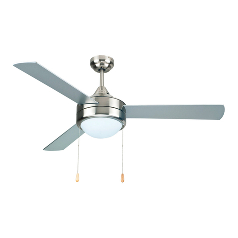
PEACOCK MURRE User manual

Before you begin, read these instructions completely and carefully.
• Be certain electrical power is OFF before and during installation, maintenance and removal.
• Fan wiring must be properly grounded in accordance with the NEC and any applicable local code requirements.
• Use only UL or IEC approved wire for input/output connections.
• Verify that supply voltage matches voltage on fan label. Installation to any other connection may void the warranty.
• Wear gloves during installation to prevent injury and do not expose wiring to metal or sharp edges.
IMPORTANT SAFETY PRECAUTIONS
WARNING: To reduce the risk of fire, electrical shock, or personal injury, mount this fan to an outlet box marked "Acceptable for Fan Support of
22.7kg (50lbs)" or less and use Mounting Screws provided with the outlet box. CAUTION: Install the primary mounting means and use only the
hardware provided with the fan.
To reduce the risk of personal injury, do not bend the blade brackets when installing the brackets, balancing the blades or clearing the fan. Be
careful not to insert foreign objects in between rotating fan blades.
To reduce the risk of fire or electrical shock, do not use this fan with any solid-state speed control device.
The important safeguards and instructions appearing in this manual are not meant to cover all possible conditions and situations that may occur.
It must be understood that common sense, caution and careful attention to detail are factors which cannot be built into this product. These
factors must be supplied by the person or persons installing, caring for, and operating the unit.
This product should be installed, inspected and maintained by a qualified and licensed electrician. Installation of luminaire must be in accordance
with NEC and local code requirements.
ELECTRIC SHOCK FALLING PARTS
ABRASIONS BURNS
MURRE CEILING FAN E26 LED
Installation Manual
SAVE THESE INSTRUCTIONS 1
REV 2023 0828
SPECIFICATIONS AND DETAILS ARE SUBJECT TO CHANGE WITHOUT NOTIFICATION. CONTACT SAGE BRANDS FOR UP TO DATE DETAILS.
PEACOCK FAN COMPANY - A DIVISION OF SAGE BRANDS • PEACOCKFAN.COM |SAGE BRANDS • SAGE.LIGHTING

MURRE CEILING FAN E26 LED
Installation Manual
SAVE THESE INSTRUCTIONS 2
REV 2023 0828
SPECIFICATIONS AND DETAILS ARE SUBJECT TO CHANGE WITHOUT NOTIFICATION. CONTACT SAGE BRANDS FOR UP TO DATE DETAILS.
PEACOCK FAN COMPANY - A DIVISION OF SAGE BRANDS • PEACOCKFAN.COM |SAGE BRANDS • SAGE.LIGHTING
DIMENSIONS
HARDWARE PARTS INCLUDED
FAN PARTS INCLUDED
PART NO. PART DESCRIPTION QTY
S1 Machine Screws 2
S2 Machine Screws 2
S3 Wood Screws 2
S4 Washers 2
S5 Lock Washers 2
S6 Star Washers 2
S7 Wire Nuts 3
S8 Bracket Screw 1
S9 Pull Chains 2
S10 Balance Kit 1
PART NO. PART DESCRIPTION QTY
1Mounting Bracket 1
2
Support Rod & Cotter Pin 1
Canopy 1
Coupler Cover 1
Fan Motor Assembly 1
Blade Arm 5
Light Kit 1
3Turn Knob 5
4Bulb 3
5Glass 1
6Rubber Washers 1
7Glass Cap 1
8Caudal 1
9Fan Blade 5
5.25"
52"
12"
20.5"
2.5"
S5S1
S6
S2
S7
S9
S3
S8
1
2
3
4
5
6
7
8
9
S10
S4

MURRE CEILING FAN E26 LED
Installation Manual
SAVE THESE INSTRUCTIONS 3
REV 2023 0828
SPECIFICATIONS AND DETAILS ARE SUBJECT TO CHANGE WITHOUT NOTIFICATION. CONTACT SAGE BRANDS FOR UP TO DATE DETAILS.
PEACOCK FAN COMPANY - A DIVISION OF SAGE BRANDS • PEACOCKFAN.COM |SAGE BRANDS • SAGE.LIGHTING
Junction box
Washer
Lock Washer
Mounting Screw
Ceiling Canopy
Support Rod
Support Rod Coupler Cover
Turn Knob
Mounting Bracket
Blade
Light Fixture
Glass Cap
Finial
Bowl Glass
Blade Holder
Switch Housing Shell
Bulb
Socket

MURRE CEILING FAN E26 LED
Installation Manual
SAVE THESE INSTRUCTIONS 4
REV 2023 0828
SPECIFICATIONS AND DETAILS ARE SUBJECT TO CHANGE WITHOUT NOTIFICATION. CONTACT SAGE BRANDS FOR UP TO DATE DETAILS.
PEACOCK FAN COMPANY - A DIVISION OF SAGE BRANDS • PEACOCKFAN.COM |SAGE BRANDS • SAGE.LIGHTING
SUPPORT ROD ASSEMBLY
MOUNTING BRACKET INSTALLATION
Note: If support rod is already assembled in the box,
skip this step.
1) Loosen the set screws in the support rod coupler
until the inside of the channel is clear of the screw tip.
Remove and save the safety pin and washer on the
end of the support rod.
2) Slide the canopy onto the support rod, followed by
the support rod coupler cover (Fig1). Feed electrical
wires from the fan housing through the support rod.
3) Thread the support rod into the support rod coupler
until the safety pin can be inserted through the hole in
both the rod and coupler. Insert the safety pin through
the hole in the support rod coupler and support rod,
then attach washer onto safety pin and the retaining
clip on the other side. Tighten both set screws and
safety screw onto the support rod coupler.
1) Install the mounting bracket onto the j-box located
in the ceiling using two machine screws, two washers,
and two lock washers (Fig 2)
2) The mounting bracket has slotted holes to enable
it to move sideways for proper alignment. Ensure the
mounting bracket is centered over the j-box and that it
is securely attached (Fig 3)
Note: Mounting bracket should be secure with no
movement between the bracket and the j-box.
3) Feed the electrical wires in the j-box through the
mounting bracket.
4) Loosen the two canopy mounting screws on the
downside face of the mounting bracket. Back them
out halfway. This will allow for easier installation of the
ceiling canopy later (Fig 4).
Junction Box
FIGURE 1
FIGURE 2 FIGURE 3
FIGURE 4
Slotted Holes
Ceiling Canopy
Mounting Screws
Safety Pin
Support Rod
Cotter Pin
Ceiling Canopy
Coupler Cover
Support Rod Coupler

MURRE CEILING FAN E26 LED
Installation Manual
SAVE THESE INSTRUCTIONS 5
REV 2023 0828
SPECIFICATIONS AND DETAILS ARE SUBJECT TO CHANGE WITHOUT NOTIFICATION. CONTACT SAGE BRANDS FOR UP TO DATE DETAILS.
PEACOCK FAN COMPANY - A DIVISION OF SAGE BRANDS • PEACOCKFAN.COM |SAGE BRANDS • SAGE.LIGHTING
HANGING THE FAN BODY
* Take note that the ball hanger on the end of the
support rod is grooved on one side (Fig 5). This is
meant to align with the keyway pin on the mounting
bracket and prevents the ceiling fan from spinning on
the mounting bracket.
1) Using your step ladder, lift the fan and place the
ball hanger in the center of the mounting bracket
with the keyway pin inserted into the groove on the
ball hanger. Turn the fan left and right to ensure it is
seated on the bracket with the pin in the groove.
2) Trim the lead wires, leaving about 6 inches of wire
extending from the support rod (Fig 7)
MAKING THE ELECTRICAL CONNECTIONS
1) Make electrical connections from fixture wires to
j-box wires.
2) Once connected, hide connections in the j-box.
Mounting Bracket
Keyway Pin
Ball
Hanger
Support
Rod
Keyway
Pin
Mounting
Bracket
Ball
Hanger
Support
Rod
Ground
Wire
Support Rod
Ball Hanger
Black
Blue
Green
White
Black
Blue
White
Green
FIGURE 5
FIGURE 7
FIGURE 8-1 FIGURE 8-2
FIGURE 6

MURRE CEILING FAN E26 LED
Installation Manual
SAVE THESE INSTRUCTIONS 6
REV 2023 0828
SPECIFICATIONS AND DETAILS ARE SUBJECT TO CHANGE WITHOUT NOTIFICATION. CONTACT SAGE BRANDS FOR UP TO DATE DETAILS.
PEACOCK FAN COMPANY - A DIVISION OF SAGE BRANDS • PEACOCKFAN.COM |SAGE BRANDS • SAGE.LIGHTING
BLADE AND BLADE ARM ASSEMBLY
LIGHT KIT INSTALLATION
Attach each fan blade to blade arm with turn knob (Fig 10). Take care not to bend the
blade arms during installation.
If applicable, attach blade arms to motor using provided screws.
If applicable, remove switch housing cover and
attached light kit. Make wiring connections.
1) Attach switch housing plate to switch housing shell
using supplied screws and secure (Fig 11).
2) Install medium base LED bulbs into sockets. Slide
glass shade over the threaded nipple, followed by the
cap and finial. Twist finial clockwise until secure.
3) Lower chain through the hold in the shade and cap.
Attach chain extensions (Fig 12)
Switch
Housing Cell
Switch
Housing Plate
Socket
Bulb
Light
Fixture
Bowl Glass
Glass
Cap Glass Cap
Finial
Finial
FIGURE 10
FIGURE 11 FIGURE 12
SECURING THE CANOPY
Slide the ceiling canopy into place over the mounting bracket. The two screws on the
bottom of the mounting bracket face should slip through the key hole slots in the
canopy. Turn the canopy slightly and tighten both screws (Fig 9).
FIGURE 9
Motor Housing
Turn-Knob (1 per blade)

MURRE CEILING FAN E26 LED
Installation Manual
SAVE THESE INSTRUCTIONS 7
REV 2023 0828
SPECIFICATIONS AND DETAILS ARE SUBJECT TO CHANGE WITHOUT NOTIFICATION. CONTACT SAGE BRANDS FOR UP TO DATE DETAILS.
PEACOCK FAN COMPANY - A DIVISION OF SAGE BRANDS • PEACOCKFAN.COM |SAGE BRANDS • SAGE.LIGHTING
MAINTENANCE
OPERATION
OPTIONAL WIRING DIAGRAMS
Your fan requires very little maintenance. Cleaning of the housing should be done with a damp soft cloth (NO CLEANING AGENTS). On the blades, use a duster or dry cloth as
moisture could cause the blades to warp.
The pull chain located on the switch housing controls
the speed of your fan. When the fan is OFF, pull the
chain once for HIGH speed, twice for MEDIUM speed,
three times for LOW speed and a fourth time to turn
it off again.
Turn fan completely off before moving the reverse
switch. Set reverse switch to recirculate air depending
on the season: UP position in winter (1), DOWN
position in summer (2). IMPORTANT: If the reverse
switch is set in the (3) middle position the fan will not
operate. Attach the pull chain extensions supplied to
ends of the pull chains.
FIGURE 14 FIGURE 15
FIGURE 13
FIGURE 16
1. 2. 3.
Reverse Switch
Fan Controlled with wall switch
and light controlled at fan
Fan Controlled at fan
with light controlled at wall switch
Fans and Lights Controlled
by wall switch or switches
Table of contents
Other PEACOCK Fan manuals