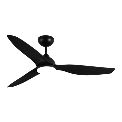
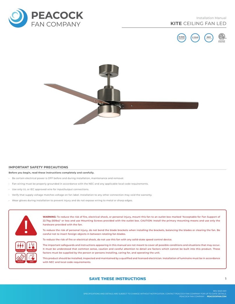
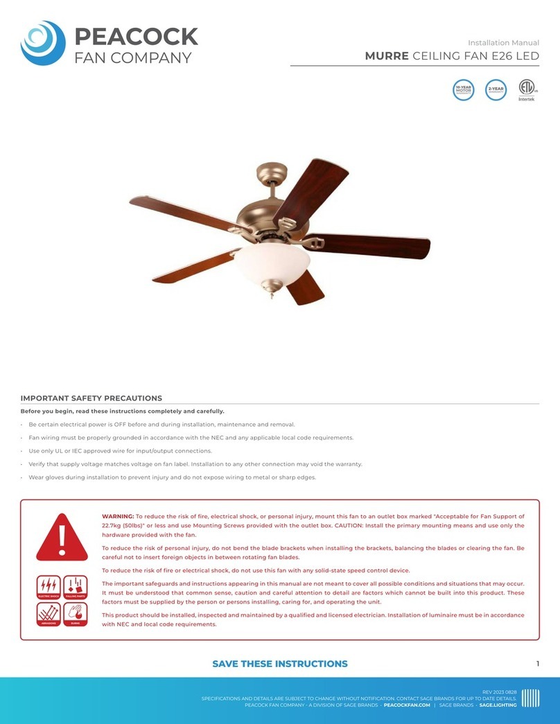
PEACOCK IBIS User manual

Before you begin, read these instructions completely and carefully.
• Be certain electrical power is OFF before and during installation, maintenance and removal.
• Fan wiring must be properly grounded in accordance with the NEC and any applicable local code requirements.
• Use only UL or IEC approved wire for input/output connections.
• Verify that supply voltage matches voltage on fan label. Installation to any other connection may void the warranty.
• Wear gloves during installation to prevent injury and do not expose wiring to metal or sharp edges.
IMPORTANT SAFETY PRECAUTIONS
WARNING: To reduce the risk of fire, electrical shock, or personal injury, mount this fan to an outlet box marked "Acceptable for Fan Support of
22.7kg (50lbs)" or less and use Mounting Screws provided with the outlet box. CAUTION: Install the primary mounting means and use only the
hardware provided with the fan.
To reduce the risk of personal injury, do not bend the blade brackets when installing the brackets, balancing the blades or clearing the fan. Be
careful not to insert foreign objects in between rotating fan blades.
To reduce the risk of fire or electrical shock, do not use this fan with any solid-state speed control device.
The important safeguards and instructions appearing in this manual are not meant to cover all possible conditions and situations that may occur.
It must be understood that common sense, caution and careful attention to detail are factors which cannot be built into this product. These
factors must be supplied by the person or persons installing, caring for, and operating the unit.
This product should be installed, inspected and maintained by a qualified and licensed electrician. Installation of luminaire must be in accordance
with NEC and local code requirements.
ELECTRIC SHOCK FALLING PARTS
ABRASIONS BURNS
IBIS CEILING FAN LED
Installation Manual
REV 2022 1115
SPECIFICATIONS AND DETAILS ARE SUBJECT TO CHANGE WITHOUT NOTIFICATION. CONTACT PEACOCK FAN COMPANY FOR UP TO DATE DETAILS.
PEACOCK FAN COMPANY • PEACOCKFAN.COM
SAVE THESE INSTRUCTIONS 1

IBIS CEILING FAN LED
Installation Manual
REV 2022 1115
SPECIFICATIONS AND DETAILS ARE SUBJECT TO CHANGE WITHOUT NOTIFICATION. CONTACT PEACOCK FAN COMPANY FOR UP TO DATE DETAILS.
PEACOCK FAN COMPANY • PEACOCKFAN.COM
SAVE THESE INSTRUCTIONS 2
DIMENSIONS
PACKAGE PARTS
TOOLS AND MATERIALS REQUIRED
6.5”
52.65”
12”
5.9”
9.4”
• Philips Screw Driver
• Flat Head Screw Driver
• 11 mm Wrench
• Step Ladder
• Wire Cutters
A) Ceiling Mounting Bracket
B) Ball/Downrod Assembly
C) Canopy
D) Joint cover
E) Fan Motor Assembly
F) Decorative covers
G) The fan blades (4)
H) A set of controllers
I) Fasteners Package
1. Mount Hardware
• Flat Washer (4)
• Wood Screw (4)
• Spring Pad (4)
• Star Washer (2)
• Screw (2)
• Fan blade set screw (13)
• Red gasket (23)
2. Balance Kit
IMPORTANT REMINDER: You must use
the parts provided with this fan for proper
installation and safety.
A
B
C
D
E
F
G
H
I

IBIS CEILING FAN LED
Installation Manual
REV 2022 1115
SPECIFICATIONS AND DETAILS ARE SUBJECT TO CHANGE WITHOUT NOTIFICATION. CONTACT PEACOCK FAN COMPANY FOR UP TO DATE DETAILS.
PEACOCK FAN COMPANY • PEACOCKFAN.COM
SAVE THESE INSTRUCTIONS 3
SPECIFICATION
FAN SIZE VOLTAGE MAX FAN POWER MAX SPEED GROSS WEIGHT NET WEIGHT
52" 120V 35W 180 RPM ± 10% 11.3 lbs 10.9 lbs
CEILING MOUNT INSTALLATION
BRACKET INSTALLATION
If there isn't an existing UL (cUL for Canadian Installation) listed junction box, then
read the following instructions
A) Disconnect the power by removing the fuses or turning off the circuit breakers.
B) Secure the junction box directly to the building structure. Use appropriate fas-
teners and building materials. The junction box and its support must be able to fully
support the moving weight of the fan (at least 50 lbs). Do not use plastic junction
boxes.
C) Figures 1 and 2 are examples of different ways to mount the junction box.
NOTE: Depending on the location you have selected for installation, you may need to
purchase and install a "Joist Hanger" for the support of the junction box. Make sure
the joist hanger you purchase has been designed for use with ceiling fans. (Figure 3)
NOTE: Ceiling mount installation should not be installed on a sloped ceiling with a
pitch greater than 30°. (Figure 4)
REMEMBER to turn off the power. Follow the steps below to hang your fan properly
Figure 1
Figure 3
Figure 2
Figure 4
Junction Box
Junction Box
Junction
Box
>30°
cUL Listed
junction box
Ceiling
Mounting
Bracket
Hook
120V Wires
Washers
Mounting screws
(supplied with junction box)

IBIS CEILING FAN LED
Installation Manual
REV 2022 1115
SPECIFICATIONS AND DETAILS ARE SUBJECT TO CHANGE WITHOUT NOTIFICATION. CONTACT PEACOCK FAN COMPANY FOR UP TO DATE DETAILS.
PEACOCK FAN COMPANY • PEACOCKFAN.COM
SAVE THESE INSTRUCTIONS 4
SCHEMATIC DIAGRAM OF THE WHOLE MACHINE INSTALLATION
Screws
Canopy
Rotating
Retaining Clip Screw
Red gasket
Fan body
The fan blade
Installing Fan Blades
Fan body
Decorative covers
Screws
Hitch pin
Coupling cover
Drop Ball Connection Diagram
Locating slot
Canopy Installation
(Connect the receiver and wire according to Figure 5 on Page 5, then lock the screw)

IBIS CEILING FAN LED
Installation Manual
REV 2022 1115
SPECIFICATIONS AND DETAILS ARE SUBJECT TO CHANGE WITHOUT NOTIFICATION. CONTACT PEACOCK FAN COMPANY FOR UP TO DATE DETAILS.
PEACOCK FAN COMPANY • PEACOCKFAN.COM
SAVE THESE INSTRUCTIONS 5
TROUBLESHOOTING
Fan will not start:
1. Check circuit fuses or breakers.
2. Check all electrical connections to ensure proper contact.
CAUTION: Make sure the main power is OFF when checking any electrical connection.
Noisy Operation:
1. Make sure all motor housing screws are snug.
2. Make sure the screws that attach the fan blade brackets to the motor are tight.
3. Ensure that the upper side of the fan blade does not touch the motor cover and the lower side does not touch the bottom cover.
4. Allow a 24-hour "breaking-in" period. Most noise associated with a new fan disappears during this time.
5. If using an optional light kit, make sure the screws securing the glassware are tight. Check that the light bulb is also secure.
6. Some fan motors are sensitive to signals from solid-state variable speed controls. If you have installed this type of control, choose and install another type of control.
7. Make sure the upper canopy is a short distance from the ceiling. It should not be touch the ceiling
Excessive Wobbling:
1. Check that all blade and blade arm screws are secure.
2. Most fan wobbling problems are caused when blade levels are unequal. Check this level by selecting a point on the ceiling above the tip of one of the blades. Measure this
distance. Rotate the fan until the next blade is positioned for measurement. Repeat for each blade. This distance should be within 1/8".
3. Use the enclosed Blade Balancing Kit if the blade wobble is still noticeable.
4. If the blade wobble is still noticeable interchanging two adjacent (side by side) blades can redistribute the weight and possibly result in smoother operation.
WARNING: To reduce the risk of personal injury, do not bend the blade arm while installing, balancing the blades, or cleaning the fan. Do not insert foreign objects
between rotating fan blades
ELECTRIC CONNECTIONS
WARNING: To avoid possible electrical shock, be sure you have turned off the power
at the main circuit panel. Follow the steps below to connect the fan to your house-
hold wiring. Use the wire nuts supplied with your fan. Secure the connectors with
electrical tape. Make sure there are no loose wire strands or connections.
A) Insert the receiver into the ceiling mounting bracket with the flat side of the
receiver facing the ceiling. For best performance, make sure the black antenna on
the end of the receiver remains extended and not tangled with any of the electrical
wires.
B) Motor to Receiver Electrical Connections
1. Connect the Brown wire from the fan to the Brown wire marked on the receiver.
2. Connect the Red wire from the fan to the Red wire marked on the receiver.
3. Connect the Gray wire from the fan to the Gray wire marked on the receiver.
4. Connect the Blue wire from the fan to the Blue wire marked on the receiver.
5. Connect the White wire from the fan to the White wire marked on the receiver.
* Steps 4-5 can be omitted if no luminaire is included.
6. Secure each set of wire connections with the plastic wire nuts provided in the
parts bag.
NOTE: The fan power wires and the grounding wires should be placed separately
on both sides of the junction box and should not be put together
C) Receiver to Supply Wires Electrical Connections:
1. Connect the Black (hot) supply wire from the ceiling junction box to the black
wire on the receiver.
2. Connect the White (neutral) supply wire from the ceiling junction box to the
White wire marked on the receiver. Secure each set of electrical connections
with the plastic wire nuts provided in the parts bag.
D) Connect the ground wire (green or bare copper) from the junction box to the
ground wire on the ceiling mounting bracket and the ground wire from the ceiling
fan.
E) After making all connections, separate the white and green wire connections to
one side and the black wire connections to the other side of the junction box.
NOTE: Fan must be installed at a maximum distance of 30 feet from the Hand Held
Remote Transmitter for optimal signal transmission between the transmitter and
the fan's receiving unit.
White (neutral)
Green or bare
Copper (ground)
Ground (green)
Junction box
Black (hot)
Black ("AC IN L")
Receiver
Gray
Brown
Red
Gray (Fan)
Brown (Fan)
Red (Fan)
Ceiling
Mounting
Bracket
Figure 5
Figure 6

IBIS CEILING FAN LED
Installation Manual
REV 2022 1115
SPECIFICATIONS AND DETAILS ARE SUBJECT TO CHANGE WITHOUT NOTIFICATION. CONTACT PEACOCK FAN COMPANY FOR UP TO DATE DETAILS.
PEACOCK FAN COMPANY • PEACOCKFAN.COM
SAVE THESE INSTRUCTIONS 6
WIRING SCHEMATIC DIAGRAM FOR RECEIVER
Inspect hand held remote transmitter and receiver for damage. Remote and receiver
must be sent back to factory for maintenance if damaged.
Receiver can be controlled from any angle in the space with the included remote, it
is not restricted by direction.
With the memory function, the remote control can save the status (light and
direction) while the fan is powered OFF and resume to the previous setting after fan
has been powered ON.
Pairing Methods
After turning on the power switch, you can hear a beep, and immediately press the
power button in the upper left corner of the remote control. When a long beep is
heard, the remote control pairing is successful.
Tip: Please ensure to follow the above within 30 seconds of turning power on. If
pairing is unsuccessful, please power off the fan for 10 seconds. After powering on,
please follow the above.
POWER PARAMETER LIST
VOLTAGE FAN (MAX) LAMP (MAX)
110-130V 50W 36W
Brown line
Gray line
Red line
TO MOTOR
AC in L Black
AC IN N white
Ground Wire/Yellow & Green Wire
Table of contents
Other PEACOCK Fan manuals
Popular Fan manuals by other brands

NuTone
NuTone Guardian AE60 Specification sheet

Faro Barcelona
Faro Barcelona Lisboa manual

Robin
Robin HEF-100 quick start guide

Optimus
Optimus F-4205 Instruction manual and owner's guide

Kichler Lighting
Kichler Lighting RIDLEY2 KLF-RIDLEY2-52-NB instruction manual

BrookVent
BrookVent AIRVENT SM ACOUSTIC Installation and operation guide