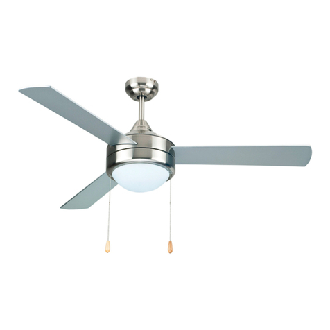
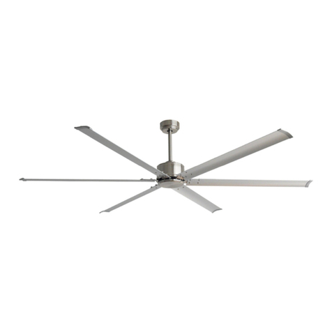
PEACOCK KIWI User manual

Before you begin, read these instructions completely and carefully.
• Be certain electrical power is OFF before and during installation, maintenance and removal.
• Fan wiring must be properly grounded in accordance with the NEC and any applicable local code requirements.
• Use only UL or IEC approved wire for input/output connections.
• Verify that supply voltage matches voltage on fan label. Installation to any other connection may void the warranty.
• Wear gloves during installation to prevent injury and do not expose wiring to metal or sharp edges.
IMPORTANT SAFETY PRECAUTIONS
WARNING: To reduce the risk of fire, electrical shock, or personal injury, mount this fan to an outlet box marked "Acceptable for Fan Support of
22.7kg (50lbs)" or less and use Mounting Screws provided with the outlet box. CAUTION: Install the primary mounting means and use only the
hardware provided with the fan.
To reduce the risk of personal injury, do not bend the blade brackets when installing the brackets, balancing the blades or clearing the fan. Be
careful not to insert foreign objects in between rotating fan blades.
To reduce the risk of fire or electrical shock, do not use this fan with any solid-state speed control device.
The important safeguards and instructions appearing in this manual are not meant to cover all possible conditions and situations that may occur.
It must be understood that common sense, caution and careful attention to detail are factors which cannot be built into this product. These
factors must be supplied by the person or persons installing, caring for, and operating the unit.
This product should be installed, inspected and maintained by a qualified and licensed electrician. Installation of luminaire must be in accordance
with NEC and local code requirements.
ELECTRIC SHOCK FALLING PARTS
ABRASIONS BURNS
KIWI CEILING FAN
Installation Manual
REV 2022 0606
SPECIFICATIONS AND DETAILS ARE SUBJECT TO CHANGE WITHOUT NOTIFICATION. CONTACT PEACOCK FAN COMPANY FOR UP TO DATE DETAILS.
PEACOCK FAN COMPANY • PEACOCKFAN.COM
SAVE THESE INSTRUCTIONS 1

KIWI CEILING FAN
Installation Manual
REV 2022 0606
SPECIFICATIONS AND DETAILS ARE SUBJECT TO CHANGE WITHOUT NOTIFICATION. CONTACT PEACOCK FAN COMPANY FOR UP TO DATE DETAILS.
PEACOCK FAN COMPANY • PEACOCKFAN.COM
SAVE THESE INSTRUCTIONS 2
DIMENSIONS
13.8”
PRODUCT PARTS
Mounting Bracket
Down Rod Assembly
Canopy
Yoke Cover
Wires
LED Light Kit Pan Assembly
Glass Shade
Fan Assembly
52”
Blades (3x)
Mounting Brackets
HARDWARE
Flat Washer (2x)
Spring Washer (2x)
Machine Screw (2x)
Mounting Screw (2x)
Blade Installation
Flat Washer (2x)
Includes 1 Spare Washer
Blade Screw (2x)
Includes 1 Spare Washer
Blade Balance
Balanced Slide (1x)
Weight Block (3G x 3)
Wire Connection
Wire Nut (3x)
Remote Control
Hardware
Mounting Screw (2x)
Wall Anchor (2x)
Wire Nut (2x)
Motor Cover

KIWI CEILING FAN
Installation Manual
REV 2022 0606
SPECIFICATIONS AND DETAILS ARE SUBJECT TO CHANGE WITHOUT NOTIFICATION. CONTACT PEACOCK FAN COMPANY FOR UP TO DATE DETAILS.
PEACOCK FAN COMPANY • PEACOCKFAN.COM
SAVE THESE INSTRUCTIONS 3
HANGING SYSTEM INSTALLATION
INSTALLING MOUNTING BRACKET TO CEILING OUTLET BOX
A) Install the mounting bracket to the outlet box in ceiling by using screws included
with the outlet box and washer from the hardware bag.
REMOVE MOTOR COVER
Loosen and remove the 3 screws from the motor body. Then remove the motor cover.
B) Loosen the bottom screws from the mounting bracket. Do not remove the screws.
Outlet Box
Mounting Bracket
Screw (2x)
Motor Cover
Jam Screw (2x)
Wires
Yoke
BLADE INSTALLATION
A) Remove 3 screws from the upper pad of motor to assemble the blades.
B) Attach blades to motor with screws from accessory bag. Repeat this step for each
blade.
C) Blades can be installed on the ground prior to attaching fan to the mounting bracket.
Blade (3x)
Motor Cover
Flat Washer (2x)
Blade Screw (2x)
Screws
ASSEMBLE MOTOR COVER
Reattach the motor cover to the motor by fastening the screws that were removed
during the previous step.
Screws
Motor Cover
Jam Screw (2x)
Wires
Yoke
Screws

KIWI CEILING FAN
Installation Manual
REV 2022 0606
SPECIFICATIONS AND DETAILS ARE SUBJECT TO CHANGE WITHOUT NOTIFICATION. CONTACT PEACOCK FAN COMPANY FOR UP TO DATE DETAILS.
PEACOCK FAN COMPANY • PEACOCKFAN.COM
SAVE THESE INSTRUCTIONS 4
F) Insert hanging ball through down rod and insert the pin back into the down rod
(removed from Steps A and B).
G) Tighten the jam screw back to the hanging ball and make sure it is tight
(loosened for Step A).
H) Insert down rod assembly into yoke. Put the cross pin through the yoke and
down rod and secure with the cotter pin (Removed for Step C).
I) Tighten both down rod jam screws to further secure the down rod. Pull down the
yoke cover.
Fan Assembly Fan Assembly
Down Rod Jam
Screws (2x)
Yoke Cover
Canopy
Jam Screw
Cross Pin
Cotter Pin
Yoke Cover
Wires
Yoke
Ball
Pin
Lead Wires
6
6
8
8
7
9
9
DOWN ROD INSTALLATION
A) Loosen the jam screw from the hanging ball and
pull it down, remove the pin from down rod and keep
it for Step F.
B) Remove the hanging ball and keep it for Step F. C) Remove cross pin and cotter pin from down rod and
keep it for Step H.
D) Loosen two down rod jam screws at yoke. E) Insert down rod through canopy and yoke cover, and feed motor lead wires
through down rod.
Pin
Jam Screw
Ball
Cotter Pin
Down Rod
Ball
Cotter Pin
Down Rod
Cross Pin
Cotter Pin
Down Rod
Fan Assembly
Jam Screw (2x)
Wires
Yoke
Down Rod
Fan Assembly
Yoke Cover
Canopy
1
1
2
3
3
4
5

KIWI CEILING FAN
Installation Manual
REV 2022 0606
SPECIFICATIONS AND DETAILS ARE SUBJECT TO CHANGE WITHOUT NOTIFICATION. CONTACT PEACOCK FAN COMPANY FOR UP TO DATE DETAILS.
PEACOCK FAN COMPANY • PEACOCKFAN.COM
SAVE THESE INSTRUCTIONS 5
LED LIGHT KIT PAN ASSEMBLY INSTALLATION
NOTICE: New models have LED Light Kit Pan Assembly installed on the fan, however terminal connections need to be made, see Step B.
Screw
B) Insert wires through the center hole of the LED
Light Kit Pan Assembly (1).
Connect 2-pin male terminal connector from LED
Light Kit Pan Assembly to 2-pin female connector
from fan (2).
1
2
LED Light Kit Pan
Assembly
C) Rotate the Light Kit Pan slightly until 2 pre-installed
screw heads are engaged in the narrow end of key holes.
Screw (2x)
Key Hole
Light Kit Pan
D) Attach screw (removed from Step A), and tighten
3 screws.
E) Connect 2-pin male terminal connector from LED
module to 2-pin female connector from fan.
Put the LED module in the middle of the LED metal pan.
The LED Module attaches to the metal pan with magnets.
Screw
A) Remove one of the 3 pre-installed screws on the
adapter.
F) Attach the glass shade onto the Light Kit Pan
Assembly.
Pay attention to the dented part inside the glass lamp
shade. Then put the dented position toward to the
protruded position inside the metal pan.
Rotate clockwise into the correct position and ensure
glass shade is tightly secured within the Light Kit Pan
Assembly.
Glass Shade
LED Metal Pan
ATTACHING FAN TO THE MOUNTING BRACKET
A) Lift the fan assembly onto the mounting bracket. B) Rotate the fan so that the groove on the ball engages the ridge in the mounting bracket.
Fan Assembly
Ball Groove
Ridge
Mounting Bracket
Mounting Bracket
LED Module

KIWI CEILING FAN
Installation Manual
REV 2022 0606
SPECIFICATIONS AND DETAILS ARE SUBJECT TO CHANGE WITHOUT NOTIFICATION. CONTACT PEACOCK FAN COMPANY FOR UP TO DATE DETAILS.
PEACOCK FAN COMPANY • PEACOCKFAN.COM
SAVE THESE INSTRUCTIONS 6
WIRING INSTALLATION
Blue (For Light Kit)
White (For Light Kit)
Pink (For Motor)
Gray (For Motor)
Red (For Motor)
Black (AC-L)
White (AC-N)
Green
(From Ground Wire)
Green
(From Hanger Ball)
Green
(From Mounting Bracket)
FROM CIRCUIT FROM RECEIVER FROM FAN
NOTE: All green grounding wires from the Hanger Ball, Mounting Bracket and
Receiver must be well attached to the Circuit Ground to prevent LED flickering.
A) There are 5 different colors on the output terminal of the receiver. Connect the same color wires on the receiver with the wires from the fan with wire nuts.
B) There are 3 wires on the input terminal (Line - Black, Neutral - White, Ground -Green). Connect the line/black wires and the neutral/white wires from the circuit to the input
terminal on the receiver. Connect the ground/green wire from the circuit to the ground/green wires from the reciever, mounting bracket and hanger ball.
CANOPY INSTALLATION
NOTICE: Two screws are pre-installed on the mounting bracket for canopy
installation.
1. Push up the canopy until the two pre-installed screws on the mounting bracket
are engaged with two key holes on canopy.
2. Rotate the canopy slightly until the two pre-installed screw heads are engaged in
the narrow end of the key holes.
3. Tighten both screws.
1Canopy
2Screw (2x)
3Key Hole (2x)
WIRING INSTALLATION
Verify that the serial number and model number match on the receiver and the transmitter.
NOTICE: Many remote sets for DC fans look the same. This remote set is pre-paired and labeled at the factory, please note the following before operation:
1a. The Remote Model Number on transmitter and receiver must be the same.
1b. The Remote Serial Number will be the same on a pre-paired remote set. If it is different, it will need to be paired (see page 9).
2. Do not mix the remote sets if you are installing more than one fan.
Fan Model Number
RECEIVER TRANSMITTER SET A SET B
DO NOT MIX
Remote Model &
Serial Number

KIWI CEILING FAN
Installation Manual
REV 2022 0606
SPECIFICATIONS AND DETAILS ARE SUBJECT TO CHANGE WITHOUT NOTIFICATION. CONTACT PEACOCK FAN COMPANY FOR UP TO DATE DETAILS.
PEACOCK FAN COMPANY • PEACOCKFAN.COM
SAVE THESE INSTRUCTIONS 7
WIRING INSTALLATION (CONTINUED)
Insert receiver into the mounting bracket.
NOTICE: Do not squeeze the wires while inserting the receiver into the mounting bracket.
Receiver
Mounting Bracket
Making electrical wiring connections.
Follow diagram below and make sure that all exposed wires are secured inside wire nuts.
NOTICE: Wires may vary in color. If the wires do NOT include a ground wire (green) to prevent flickering, this unit must be grounded to the circuit's ground wire. Please
consult an electrician.
After wiring is completed, gently push wires into junction box with wire nuts pointing upward.
Blue (For Light Kit)
White (For Light Kit)
Pink (For Motor)
Gray (For Motor)
Red (For Motor)
Black (AC-L)
White (AC-N)
Green
(From Ground Wire)
Green
(From Hanger Ball)
Green
(From Mounting Bracket)
FROM CIRCUIT FROM RECEIVER FROM FAN
NOTE: All green grounding wires from the Hanger Ball, Mounting Bracket and
Receiver must be well attached to the Circuit Ground to prevent LED flickering.
REMOTE TRANSMITTER ASSEMBLY
A) Remove the back cover by
loosening the screw.
B) Install the 12V battery (included in
accessory bag).
C) Reattach the back cover.
BACK COVER BACK COVER

KIWI CEILING FAN
Installation Manual
REV 2022 0606
SPECIFICATIONS AND DETAILS ARE SUBJECT TO CHANGE WITHOUT NOTIFICATION. CONTACT PEACOCK FAN COMPANY FOR UP TO DATE DETAILS.
PEACOCK FAN COMPANY • PEACOCKFAN.COM
SAVE THESE INSTRUCTIONS 8
OPERATIONAL INSTRUCTIONS
2. ON/OFF - Light
3. Fan Direction
3. Fan Speed
1 - Low Speed / 5 - High Speed
1. ON/OFF - Fan
7. 12V Battery (1x)
Fan must be installed at a maximum distance of 32' from the remote control for
proper signal transmission between the remote control and the fan's receiver.
1. ON/OFF - Fan Operation
2. ON/OFF - Light Operation
3. Fan Speed: 1 - Low Speed / 5 - High Speed
4. Direction of the Fan (Reverse Switch)
5. Fan Control Timer (1 hour / 4 hours / 8 hours)
6. LED Indicator Light
7. 1x 12V Battery (Included)
NOTES
1. With the memory function, the controller will save the last fan function when
the fan is powered OFF. When restoring the power supply it will resume to the
original status (fan is OFF and light is ON).
2. If not used for a long period of time, remove battery to prevent damage to the
transmitter. Store the remote away from excessive heat or humidity.
6. Indicator Light
BREAKER BOX
Return power to the breaker box.
ON

KIWI CEILING FAN
Installation Manual
REV 2022 0606
SPECIFICATIONS AND DETAILS ARE SUBJECT TO CHANGE WITHOUT NOTIFICATION. CONTACT PEACOCK FAN COMPANY FOR UP TO DATE DETAILS.
PEACOCK FAN COMPANY • PEACOCKFAN.COM
SAVE THESE INSTRUCTIONS 9
PAIRING PROCESS FOR REMOTE AND RECEIVER
1. Switch off the main power at the breaker.
2. Install a new receiver or install the battery in a new remote before the pairing process
3. Switch on the main power and immediately:
- Press and hold the button for 8 seconds until the receiver "long beeps"
- This process must be done within 20 seconds of switching the main power back ON
PAIRING PROCESS FOR MULTIPLE FANS (ONE REMOTE FOR MULTIPLE RECEIVERS)
If you wish to use only one remote for two fans, simply wire up both fans one at a time and perform the pairing process from a point between two fans.
FAN 1 FAN 2
REMOTE PAIRING PROCESS
The pairing process is only necessary when there is an issue. The remote is pre-paired from the factory and should not require the pairing process.
A fan may need to have the pairing process performed for the following issues:
1. Replacing the remote
2. Replacing the receiver
3. Multiple fans on the same circuit
- In a multiple fan situation, each fan must be wired up individually for the pairing process (see steps below)
In the event the fan does not operate properly, please perform the following steps:
A) Lower the canopy and check that all wires are connected properly
B) Perform the remote pairing process (Page 9)
Blue (For Light Kit)
White (For Light Kit)
Pink (For Motor)
Gray (For Motor)
Red (For Motor)
Black (AC-L)
White (AC-N)
Green
(From Ground Wire)
Green
(From Hanger Ball)
Green
(From Mounting Bracket)
FROM CIRCUIT FROM RECEIVER FROM FAN
NOTE: All green grounding wires from the Hanger Ball, Mounting Bracket and
Receiver must be well attached to the Circuit Ground to prevent LED flickering.
TROUBLESHOOTING

KIWI CEILING FAN
Installation Manual
REV 2022 0606
SPECIFICATIONS AND DETAILS ARE SUBJECT TO CHANGE WITHOUT NOTIFICATION. CONTACT PEACOCK FAN COMPANY FOR UP TO DATE DETAILS.
PEACOCK FAN COMPANY • PEACOCKFAN.COM
SAVE THESE INSTRUCTIONS 10
Mounting Bracket
Canopy
FAN 1 REMOTE SET UP
Switch off the main power at the breaker and disconnect the BLACK wire from Fan 2.
Before starting the remote control pairing process, lower the canopy of Fan 2 and disconnect the BLACK wire. Put the wire nut on the BLACK wire from the circuit.
Disconnect
Outlet Box
FAN 1 FAN 2
Turn ON main power and Fan 1 is ready for pairing.
*See the remote control pairing process at the top of this page to
set up Fan 1.
FAN 2 REMOTE SET UP
Switch off the main power at the breaker and disconnect the BLACK wire from Fan 1.
Disconnect the BLACK wire from FAN 1 and connect the BLACK wire back to FAN 2 that was removed in the previous step.
FAN 1 FAN 2
Mounting Bracket
Canopy
Mounting Bracket
Disconnect
Outlet Box
Outlet Box
Turn ON main power and Fan 2 is ready for pairing.
*See the remote control pairing process at the top of page 10 to set up Fan 2.
PAIRING PROCESS FOR MULTIPLE FANS (ONE REMOTE FOR ONE RECEIVER)
The pairing process must be performed on each remote set (remote and receiver) individually. See steps belows.

KIWI CEILING FAN
Installation Manual
REV 2022 0606
SPECIFICATIONS AND DETAILS ARE SUBJECT TO CHANGE WITHOUT NOTIFICATION. CONTACT PEACOCK FAN COMPANY FOR UP TO DATE DETAILS.
PEACOCK FAN COMPANY • PEACOCKFAN.COM
SAVE THESE INSTRUCTIONS 11
RECONNECT ALL FANS
After all the fans have completed the pairing process, reconnect all the wires for Fan 1 and Fan 2 and lift up the canopy Fan 1 and Fan 2.
FAN 1 FAN 2
Mounting Bracket
Canopy
Mounting Bracket
Outlet Box Outlet Box
Switch on the main power and now each of the fans are controlled by their own individual remote.
FAN 1 FAN 2
ON
NOTE: For more that 2 fans, follow the same steps. Make sure only
one fan is connected to power at a time when doing remote pairing.
All connected fans should be disconnected until all have completed
the remote pairing process.
Table of contents
Other PEACOCK Fan manuals