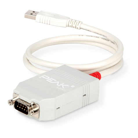
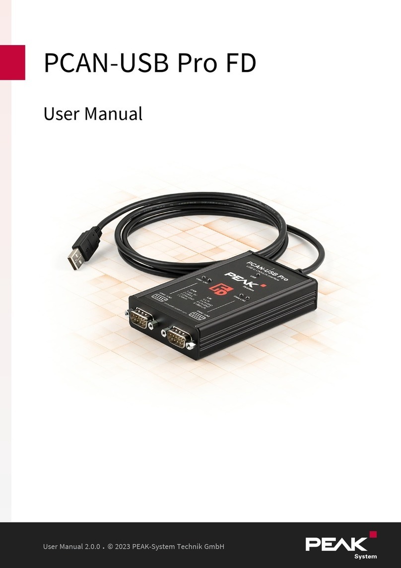
Peak PCAN-USB FD User manual

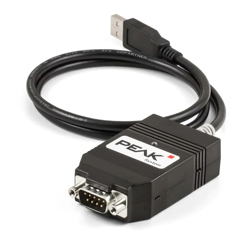
PCAN-USBFD
User Manual
User Manual 2.1.0 © 2023 PEAK-System Technik GmbH

Relevant Products
Product name Part number
PCAN-USBFD IPEH-004022
Imprint
PCAN is a registered trademark of PEAK-System Technik GmbH. CiA® is a registered community trade
mark of CAN in Automation e.V.
All other product names in this document may be the trademarks or registered trademarks of their
respective companies. They are not explicitly marked by ™ or ®.
© 2023 PEAK-System Technik GmbH
Duplication (copying, printing, or other forms) and the electronic distribution of this document is only
allowed with explicit permission of PEAK-System Technik GmbH. PEAK-System Technik GmbH reserves
the right to change technical data without prior announcement. The general business conditions and
the regulations of the license agreement apply. All rights are reserved.
PEAK-System Technik GmbH
Otto-Röhm-Straße 69
64293 Darmstadt
Germany
Phone: +49 6151 8173-20
Fax: +49 6151 8173-29
www.peak-system.com
Document version 2.1.0 (2023-08-29)
Relevant Products PCAN-USBFD
User Manual 2.1.0 © 2023 PEAK-System Technik GmbH
2

Contents
Imprint 2
Relevant Products 2
Contents 3
1 Introduction 5
1.1 Properties at a Glance 6
1.2 System Requirements 7
1.3 Scope of Supply 7
2 Settings 8
2.1 Voltage Supply of External Devices 8
2.2 Internal Termination 10
3 Installation 12
3.1 Install Device Driver Setup 12
3.2 Connecting the CAN Interface 13
3.3 Check Operational Readiness 13
4 Connecting the CAN Bus 14
4.1 Connection over D-Sub Connector 14
4.2 Cabling 15
4.3 Example Application under Windows 16
5 Operation 17
5.1 Status LED 17
5.2 Unplugging the USB Connection 17
5.3 Distinguishing several PCAN-USBFDInterfaces 17
6 CAN Monitor PCAN-View 18
6.1 Initialize CAN interface 19
6.2 Transmit CAN message 21
6.3 Additional Tabs 22
7 API PCAN-Basic 27
7.1 Features of PCAN-Basic 28
7.2 Principle Description of the API 29
Contents PCAN-USBFD
User Manual 2.1.0 © 2023 PEAK-System Technik GmbH
3

1 Introduction
The PCAN-USBFD interface enables simple connection to CANFD and CAN
networks. Its compact plastic casing makes it suitable for mobile applications. A
galvanic isolation of up to 500 Volts decouples the PC from the CANbus.
The CAN FD standard (CAN with Flexible Data rate) is primarily characterized by
higher bandwidth for data transfer. The maximum of 64 data bytes per CAN FD
frame (instead of 8 so far) can be transmitted with bit rates up to 12 Mbit/s. CAN FD
is downward compatible to the CAN 2.0 standard, CAN FD nodes can be inserted
into already existing CAN networks without CAN FD extensions.
The monitor software PCAN-View and the programming interface PCAN-Basic for
the development of applications with CAN connection are included in the scope of
supply and support CAN FD.
Device drivers exist for different operating systems, so programs can easily access a
connected CAN bus.
This manual describes the use of the CAN interface with Windows.
Device drivers and application information for Linux:
www.peak-system.com/quick/DL-Driver-E
At the end of this manual you can find a Quick Reference with brief
information about the installation and operation of the PCAN-USBFD
interface.
1 Introduction PCAN-USBFD
User Manual 2.1.0 © 2023 PEAK-System Technik GmbH
5

1.1 Properties at a Glance
■CAN interface for High-speed USB2.0 (compatible to USB1.1 and USB3.0)
■High-speed CAN connection (ISO11898-2)
■Complies with CAN specifications ISO 11898-1 for CAN and CAN FD
■CANFD support for ISO and Non ISO standard switchable
■CANFD bit rates for the data field (64bytes max.) from 25kbit/s up to 12Mbit/s
■CAN bit rates from 25kbit/s up to 1Mbit/s
■CAN bus connection via D-Sub, 9-pin (in accordance with CiA®106)
■Time stamp resolution 1µs
■FPGA implementation of the CANFD controller
■NXP CAN transceiver TJA1044GT
■Galvanic isolation on the CAN connection up to 500 V
■CAN termination can be activated through a solder jumper
■Measurement of bus load including error frames and overload frames
on the physical bus
■Induced error generation for incoming and outgoing CAN messages
■5-Volt supply to the CAN connection can be connected through a
solderjumper,e.g. for external bus converter
■Voltage supply via USB
■Extended operating temperature range from -40 to +85 °C (-40 to +185 °F)
1 Introduction PCAN-USBFD
User Manual 2.1.0 © 2023 PEAK-System Technik GmbH
6
1.2 System Requirements
Computer with
■operating system Windows 11 (x64/ARM64), 10(x64), or Linux
■a vacant USB port (USB 1.1, USB 2.0, or USB 3.0) or
■a vacant USB port at a self-powered USB hub
1.3 Scope of Supply
■PCAN-USBFD in plastic casing
Downloads
■Device drivers for Windows 11 (x64/ARM64), 10(x64), and Linux
■CAN monitor PCAN-View for Windows
■Programming interface PCAN-Basic for developing applications with CAN
connection
■Programming interfaces for standardized protocols from the automotive sector
■Manual in PDF format
1 Introduction PCAN-USBFD
User Manual 2.1.0 © 2023 PEAK-System Technik GmbH
7

2 Settings
The following describes the settings for the power supply of external devices and
the internal termination. If you do not need any of these settings, skip this chapter.
2.1 Voltage Supply of External Devices
Optionally, an external power supply can be connected via the D-Sub connector
using solder bridges at pin 1 and/or pin 9 on the D-Sub connector. This allows
external devices to be supplied with a voltage of 5 V DC, such as the PCAN-TJA1054
bus converter for Low-speed CAN. Pin 1 is not assigned at delivery. The current
output is limited to 50mA.
2.1.1 Activate Power Supply
Risk of short circuit! Soldering on the CAN interface may only be
performed by qualified electrical engineering personnel.
Attention! Electrostatic discharge (ESD) can damage or destroy
components on the card. Take precautions to avoid ESD.
2 Settings PCAN-USBFD
User Manual 2.1.0 © 2023 PEAK-System Technik GmbH
8

1. Open the CANinterface casing. Push the latches on both sides cautiously with a
slotted screwdriver.
2. Remove the circuit board.
3. Set the corresponding solder bridges on the circuit board.
Circuit boards of the published hardware versions
4. For assembly, place the circuit board on the upper half of the housing. The
strain relief and the LED must be in the corresponding recesses.
5. Press the lower half of the housing onto the upper half of the housing until the
latches engage.
Attention! The voltage supply for external devices is not protected
separately. Therefore, turn off the computer before you connect and
disconnect CAN cables or peripheral systems. Consider that some
computers still supply the USB ports with power even when they are
turned off (standby operation).
2 Settings PCAN-USBFD
User Manual 2.1.0 © 2023 PEAK-System Technik GmbH
9

2.2 Internal Termination
The internal termination can be activated by solder jumpers on the circuit board to
terminate one end of the CANbus. At delivery the termination is not activated.
Tipp: We recommend to do termination at the CAN cabling, for
example with the terminating resistors PCAN-Term (IPEK-003002) or
PCAN-MiniTerm (IPEK-003002-Mini). Thus, CAN nodes can be flexibly
connected to the bus.
2.2.1 Activate Internal Termination
Risk of short circuit! Soldering on the CAN interface may only be
performed by qualified electrical engineering personnel.
Attention! Electrostatic discharge (ESD) can damage or destroy
components on the card. Take precautions to avoid ESD.
2 Settings PCAN-USBFD
User Manual 2.1.0 © 2023 PEAK-System Technik GmbH
10

1. Open the CAN interface casing. Push the latches on both sides cautiouslywith a
slotted screwdriver.
2. Remove the circuit board.
3. Set the corresponding solder bridges on the circuit board.
Circuit boards of the published hardware versions
4. For assembly, place the circuit board on the upper half of the housing. The
strain relief and the LED must be in the corresponding recesses.
5. Press the lower half of the housing onto the upper half of the housing until the
latches engage.
2 Settings PCAN-USBFD
User Manual 2.1.0 © 2023 PEAK-System Technik GmbH
11

3 Installation
This chapter covers the software setup for the PCAN-USBFDinterface under
Windows and the connection of the CANinterface to the computer.
Note: For installation on Linux, see Appendix E Linux.
Install the driver before you connect the CAN interface.
3.1 Install Device Driver Setup
1. Download the device driver setup from our website:
www.peak-system.com/quick/DL-Driver-E
2. Unpack the file PEAK-System_Driver-Setup.zip
3. Double-click the file PeakOemDrv.exe
The driver setup starts.
4. Follow the program instructions.
3 Installation PCAN-USBFD
User Manual 2.1.0 © 2023 PEAK-System Technik GmbH
12

3.2 Connecting the CAN Interface
Attention! Do not use a USB extension cable to connect the
CANinterface to the computer. Extension cables does not comply
with the USB specification.
1. Connect the CANinterface to a USB port of the computer or of a connected USB
hub. The computer can remain powered on.
Windows detects the new hardware and completes the driver installation.
2. Check the LED on the CANinterface. If the LED is green, then the driver was
initialized successfully.
3.3 Check Operational Readiness
1. Open the Windows Start menu.
2. Type Peak Settings and press |Enter|.
The window PEAK Settings appears.
3. Select CAN Hardware.
The connected CAN interface is displayed.
3 Installation PCAN-USBFD
User Manual 2.1.0 © 2023 PEAK-System Technik GmbH
13

4 Connecting the CAN Bus
4.1 Connection over D-Sub Connector
After the CAN interface is connected, a CAN bus can be connected to the
D-Subconnector. The pin assignment for CAN corresponds to the specification
CiA®106:
Pin Assignment D-Sub plug
1 CAN_V+ (optional)
2 CAN_Low
3 CAN_GND
4 Not connected
5 Not connected
6 CAN_GND
7 CAN_High
8 Not connected
9 Not connected
Low power devices can be supplied directly with 5 Volts over pin1 of the CAN
connector, for example bus converters. Pin 1 is not in use at the delivery state. For
more information see section 2.1 Voltage Supply of External Devices.
Tip: Connect a CAN bus with a different transmission standard via a
bus converter. PEAK-System offers different bus converter modules
like the PCAN-TJA1054 for a Low-speed CAN bus according to ISO
11898-3.
4 Connecting the CAN Bus PCAN-USBFD
User Manual 2.1.0 © 2023 PEAK-System Technik GmbH
14

4.2 Cabling
4.2.1 Termination
The High-speed CAN bus (ISO 11898-2) must be terminated with 120 Ω on both
ends. The termination prevents interfering signal reflections and ensures the
proper operation of the transceivers of the connected CAN nodes (CAN interfaces,
controldevices).
The PCAN-USBFD has an optional internal termination with 120Ω. For more
information see chapter 2.2 Internal Termination.
4.2.2 Example of a Connection
This example shows a connection between the PCAN Interface and a control unit
(ECU). The upper example shows a connection with a cable which is terminated
with 120 Ω at both ends. At the lower example the connection is made with
termination adapters.
4 Connecting the CAN Bus PCAN-USBFD
User Manual 2.1.0 © 2023 PEAK-System Technik GmbH
15

4.2.3 Maximum Bus Length
The maximum bus length depends primarily on the bit rate:
Nominal bit rate Buslength
1 Mbit/s 40 m
500 kbit/s 110 m
250 kbit/s 240 m
125 kbit/s 500 m
50 kbit/s 1.3 km
25 kbit/s 2.5 km
The listed values have been calculated on the basis of an idealized system and can
differ from reality.
Note: For CAN FD, the same maximum bus lengths applys as for CAN,
despite the higher data bit rate of CAN FD. The dependency is based
on the bit rate during the arbitration, called nominal bit rate.
4.3 Example Application under Windows
As an example application for accessing the CAN interface, run the CAN monitor
PCAN-View from the Windows Start menu.
4 Connecting the CAN Bus PCAN-USBFD
User Manual 2.1.0 © 2023 PEAK-System Technik GmbH
16

5 Operation
5.1 Status LED
The LED can be in the following states:
Status Meaning
Green on There's a connection to a driver of the operating system.
Green slow blinking A software application is connected to the interface.
Green quick blinking Data is transmitted via the connected CANbus.
Red blinking An error is occurring during the transmission of CANdata.
Orange quick blinking Identification of an interface when multiple interfaces are plugged.
5.2 Unplugging the USB Connection
The PCAN-USBFD interface can be disconnected from the computer without
further actions. In Windows, the interface is not listed under "Safely Remove
Hardware".
5.3 Distinguishing several PCAN-USBFDInterfaces
You can operate several PCAN-USBFD interfaces on a single computer at the same
time. The supplied program PCAN-View allows the assignment of device IDs in
order to distinguish the CANinterfaces in a software environment.
5 Operation PCAN-USBFD
User Manual 2.1.0 © 2023 PEAK-System Technik GmbH
17

6 CAN Monitor PCAN-View
The CAN monitor PCAN-View is a Windows software for viewing, sending, and
recording CAN and CAN FD messages. The software is installed with the installation
of the device driver package under Windows.
In the following the initialization of a CAN interface is described as an example.
Detailed information about using PCAN-View can be found in the program window
under the menu item Help.
6 CAN Monitor PCAN-View PCAN-USBFD
User Manual 2.1.0 © 2023 PEAK-System Technik GmbH
18

6.1 Initialize CAN interface
1. Open the program PCAN-View via the Windows Start menu.
Depending on the CAN interface the Connect dialog is displayed with or without
settings for CAN FD.
CAN CAN FD
CAN interface List entry in Available Hardware
USB Interface, 1-channel see example above
USB Interface, 2-channel
PCIe Interface, 2-channel
6 CAN Monitor PCAN-View PCAN-USBFD
User Manual 2.1.0 © 2023 PEAK-System Technik GmbH
19

2. If there are several CAN interfaces, select the desired interface. For multiple
channels, select the desired channel from the list.
3. Enter the bit rate(s) and other settings according to the connected CAN bus.
4. Confirm the entries with OK. The main window appears and displays the
Receive/Transmittab.
5. For initializing another channel or CAN interface, open another instance of
PCAN-View.
6 CAN Monitor PCAN-View PCAN-USBFD
User Manual 2.1.0 © 2023 PEAK-System Technik GmbH
20
Other manuals for PCAN-USB FD
1
Table of contents
Other Peak Adapter manuals

Peak
Peak RS-232 User manual

Peak
Peak PCAN-LIN Series User manual

Peak
Peak PCAN-Optoadapter User manual

Peak
Peak PCAN-DONGLE IPEH-002015 User manual

Peak
Peak PCIe-miniPCIe User manual

Peak
Peak PCAN-USB X6 User manual

Peak
Peak PLIN-USB User manual

Peak
Peak PCAN-PC/104-Plus User manual

Peak
Peak PCAN-AU5790 User manual

Peak
Peak PCAN-Optoadapter User manual