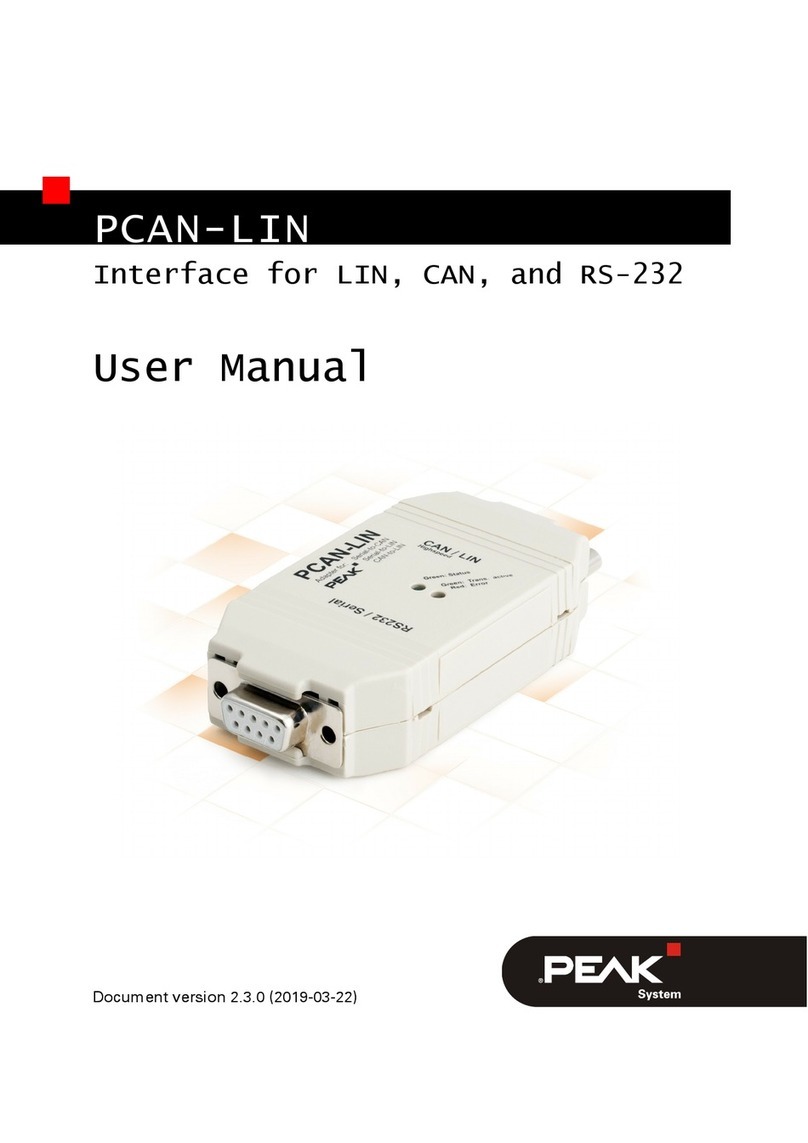
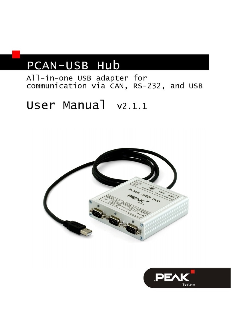
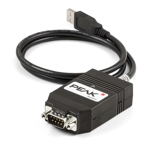
Peak PLIN-USB User manual

PLIN-USB
User Manual
User Manual 2.1.0 © 2023 PEAK-System Technik GmbH

Relevant Products
Product name Part number
PLIN-USB IPEH-004052
Imprint
PLIN is a registered trademark of PEAK-System Technik GmbH.
All other product names in this document may be the trademarks or registered trademarks of their
respective companies. They are not explicitly marked by ™ or ®.
© 2023 PEAK-System Technik GmbH
Duplication (copying, printing, or other forms) and the electronic distribution of this document is only
allowed with explicit permission of PEAK-System Technik GmbH. PEAK-System Technik GmbH reserves
the right to change technical data without prior announcement. The general business conditions and
the regulations of the license agreement apply. All rights are reserved.
PEAK-System Technik GmbH
Otto-Röhm-Straße 69
64293 Darmstadt
Germany
Phone: +49 6151 8173-20
Fax: +49 6151 8173-29
www.peak-system.com
Document version 2.1.0 (2023-09-08)
Relevant Products PLIN-USB
User Manual 2.1.0 © 2023 PEAK-System Technik GmbH
2

Contents
Imprint 2
Relevant Products 2
Contents 3
1 Introduction 5
1.1 Properties at a Glance 5
1.2 System Requirements 6
1.3 Scope of Supply 6
2 Installation 7
2.1 Install Software and Driver 7
2.2 Connection 7
2.3 Check Operational Readiness 8
2.4 Connect LIN Bus 8
2.5 Example Application under Windows 8
3 Operation 9
3.1 Status LED 9
3.2 Unplugging the USB Connection 9
3.3 Distinguishing several PLIN-USB 9
4 LIN Monitor PLIN-View Pro 11
4.1 Features 12
4.2 StartandInitializePLIN-ViewPro 13
4.3 Receive / Transmit Tab 15
4.4 Transmit a LIN Frame 15
4.5 Trace Tab 18
4.6 Scripting Tab 19
4.7 LIN Interface Tab 20
5 PLIN-API 21
5.1 Features 22
Contents PLIN-USB
User Manual 2.1.0 © 2023 PEAK-System Technik GmbH
3

1 Introduction
The PLIN-USB enables the connection of a Windows computer to a LIN network via
USB. The LIN interface supports the LIN protocol according to the standard ISO
17987 and complies with all LIN specifications up to version 2.2. The interface can
be operated as a master or a slave.
The monitor application PLIN-View Pro as well as the PLIN programming interface
for the development of applications with LIN connection are included in the scope
of delivery.
1.1 Properties at a Glance
■LIN interface for the USB connection (Full-Speed mode, compatible with
USB1.1, USB 2.0, and USB 3.0)
■LIN connection (ISO 17987)
■Complies with all LIN specifications (up to version 2.2)
■Bit rates from 1 kbit/s up to 20 kbit/s
■Can be used as a LIN master or slave (1 ms master task resolution)
■Automatic bit rate, frame length, and checksum type recognition
■Autonomous scheduler with support for unconditional, event, and sporadic
frames
■LIN bus connection via D-Sub, 9-pin
■LIN connection short-circuit-proof against transceiver supply and ground
■NXP LIN transceiver TJA1028T or TI LIN transceiver TLIN1028D
■Galvanic isolation on the LIN connection up to 500 V
■Indicator LED for interface status
■Voltage supply 5 V DC via USB port
■Transceiver supply 6 to 28 V DC via D-Sub, pin 9
■Extended operating temperature range from -40 to +85 °C (-40 to +185 °F)
1 Introduction PLIN-USB
User Manual 2.1.0 © 2023 PEAK-System Technik GmbH
5
1.2 System Requirements
■Computer with:
■Operating system Windows11(x64/ARM64), 10(x64), or Linux
■a vacant USB port (USB 1.1, USB 2.0, or USB 3.0)
■Power supply with nominal voltage between 6 and 28 V DC
1.3 Scope of Supply
■PLIN-USB in plastic casing
Downloads
■Device drivers package for Windows11(x64/ARM64), 10(x64) including:
■LIN device driver
■LIN monitor PLIN-View Pro
■Device driver for Linux
■Programming interface PLIN-API for Windows11(x64/ARM64), 10(x86/x64)
■Manual in PDF format
Optional accessories
■LIN connection cable for PC LIN interfaces (IPEK-003013)
1 Introduction PLIN-USB
User Manual 2.1.0 © 2023 PEAK-System Technik GmbH
6

2 Installation
This chapter covers the software setup for the LIN interface PLIN-USB under
Windows and the connection of the LIN interface to the computer.
Install the device drivers package before you connect the LIN interface.
2.1 Install Software and Driver
1. Download the device drivers package from our website:
www.peak-system.com/quick/DL-Driver-E.
2. Extract the file PEAK-System_Driver-Setup.zip
3. Double-click the file PeakOemDrv.exe
The driver setup starts.
4. Confirm the start and the license agreements.
5. Follow the program's instructions. When selecting components, select the LIN
device driver (other components as needed).
The LIN monitoring software PLIN-View Pro is installed automatically.
2.2 Connection
Note: Do not use a USB extension cable to connect the LINinterface
to the computer. Extension cables do not comply with the USB
specification.
1. Connect the LIN interface to a USB port on the computer or to a USB hub.
Windows notifies you about the new hardware and completes the driver
installation.
2. Check the status LED. If the LED is green, the driver has been successfully
initialized.
2 Installation PLIN-USB
User Manual 2.1.0 © 2023 PEAK-System Technik GmbH
7

2.3 Check Operational Readiness
1. Open the Windows Start menu.
2. Type Peak Settings and press |Enter|.
The window PEAK Settings appears.
3. Select LIN Hardware.
The connected CAN interface is displayed.
2.4 Connect LIN Bus
The transceiver of the LIN interface requires a power supply between 6 and 28 V
DC. This must be provided via pin 9 on the D-Sub connector.
To facilitate the connection, use the optional LIN connection cable for PC LIN
interfaces (IPEK-003013).
Pin Assignment D-Sub plug on LIN interface
1 None
2 None
3 None
4 LIN
5 LIN_GND
6 LIN_GND
7 None
8 None
9 LIN_VBat
2.5 Example Application under Windows
As an example application for accessing the LIN interface, run the LIN monitor
PLIN-ViewPro from the Windows Start menu.
2 Installation PLIN-USB
User Manual 2.1.0 © 2023 PEAK-System Technik GmbH
8

3 Operation
3.1 Status LED
LED status Meaning
Green on There's a connection to a driver of the operating system.
Green slow blinking The LIN interface is initialized with a valid bitrate. A software application
is connected to the LIN interface.
Green quick blinking Data is transmitted via the connected LIN bus.
3.2 Unplugging the USB Connection
The LIN interface can be disconnected from the computer without further actions.
In Windows, the LIN interface is not listed under "Safely Remove Hardware".
3.3 Distinguishing several PLIN-USB
You can operate several PLIN-USB interfaces on a single computer at the same
time. For this purpose, the device ID can be determined in order to distinguish the
LINinterfaces in a software environment.
PLIN-View Pro
To set the device ID in PLIN-View Pro:
1. Open the tab PLIN-USB.
2. Enter a hexadecimal number with suffix “h” as the new hardware ID.
3. Confirm the entry with Set.
PEAK Settings
To set the device ID in PEAK Settings:
3 Operation PLIN-USB
User Manual 2.1.0 © 2023 PEAK-System Technik GmbH
9

1. Select LIN hardware.
The installed hardware is displayed.
2. Click on PLIN-USB.
The view expands and the current ID is displayed in an input field.
3. Enter a hexadecimal number with suffix “h” as the new Device ID.
4. Confirm the entry with Set.
3.3.1 Identifikation
If you have connected several PLIN-USB interfaces you can identify a single
interface via PEAKSettings.
1. Select LIN hardware.
The installed hardware is displayed.
2. Click on PLIN-USB.
The view expands and the Identify button is displayed.
3. Click on Identify.
The LED of the selected PLIN-USB flashes orange for five seconds.
3 Operation PLIN-USB
User Manual 2.1.0 © 2023 PEAK-System Technik GmbH
10

4 LIN Monitor PLIN-View Pro
The LIN monitor PLIN-View Pro is a Windows software for viewing, sending and
recording LIN messages. The software is installed ready for operation under
Windows with the installation of the device driver package.
In the following the initialization of a LIN interface is described as an example.
Detailed information on the use of PLIN-View Pro can be found in the program
window under the menu item Help.
4 LIN Monitor PLIN-View Pro PLIN-USB
User Manual 2.1.0 © 2023 PEAK-System Technik GmbH
11

4.1 Features
■Display of incoming LIN frames
■Symbolic display of LIN messages (LDF files)
■Master or Slave mode
■Administration and processing of schedule tables
■Configurable recording of LIN frames (trace)
■Display and recording of frame events such as bus sleep, bus wake-up, and
overrun
■Automation of various processes with VBScript
■Automation of LIN data and elements with C# scripts; optional use of
C#assemblies
■Integrated text editor for C# with syntax highlighting
■Separate views for:
■Transmit and Receive
■Trace (data logger)
■Scripting
■Connected LIN interface
4 LIN Monitor PLIN-View Pro PLIN-USB
User Manual 2.1.0 © 2023 PEAK-System Technik GmbH
12

4.2 StartandInitializePLIN-ViewPro
1. From the Windows Start menu, select PLIN-View Pro.
The main window and the Connect to ... dialog box for selecting the
LINhardware appear. The parameters for the LIN interface are set in the dialog
window.
Selection of the hardware as master. Selection of the hardware as slave.
2. If there are several LIN interfaces, select the desired interface. If there are
several channels, select the desired channel from the list.
3. Determine the operation Mode to be used for the LIN connection.
4 LIN Monitor PLIN-View Pro PLIN-USB
User Manual 2.1.0 © 2023 PEAK-System Technik GmbH
13

4. If the bit rate is known: Select the bit rate of the LIN bus from the Bit rate list.
If the bit rate is unknown: Determine the bit rate under Bit rate detection with
Detect.
Note: The LIN interface must not be initialized by any other software.
Bit rate detection as master. Bit rate detection as slave.
5. Confirm the settings with OK.
6. Optional: To initialize another channel or LIN interface, open another instance of
PLIN-ViewPro.
4 LIN Monitor PLIN-View Pro PLIN-USB
User Manual 2.1.0 © 2023 PEAK-System Technik GmbH
14

4.3 Receive / Transmit Tab
In the upper area, the Receive / Transmit tab displays the Recieve window for
received LIN frames. Depending on the operation mode Master or Slave, the lower
area shows the Transmit window for the operation mode „Master“ or Publish for
„Slave“. If the master requests data from a slave, the slave can publish the data in
the LIN frame.
In the Global Frame Table all 64 defined LIN frame entries are stored, which can be
processed with the LIN interface (LINID0x00to0x3F). To send a LIN frame, the
underlying frame definition must be adapted in the Properties window.
4.4 Transmit a LIN Frame
Depending on the customer's requirements, different scenarios for sending LIN
frames are possible.
4 LIN Monitor PLIN-View Pro PLIN-USB
User Manual 2.1.0 © 2023 PEAK-System Technik GmbH
15

4.4.1 With LDF (LIN Description File)
Note: An LDF must be provided by the system manufacturer of the LIN
bus or created by the customer.
Application examples with an LDF:
■Master with scheduler: The Publisher data is edited in the Transmit window
and assigned to the Scheduler with the |Space bar|.
■Slave (Listen Only): Selecting "All - Listen Only" will receive the data as a silent
listener.
■Slave (LIN node simulation): The publisher data of the slave are changed in
the Publish window. With the |Space bar|the data is sent to the hardware and
thus made available on the LIN bus.
■Master with LIN diagnostic frames: Diagnostic frames 3C/3D are processed via
a script to be created by the customer for the LDF used. Examples can be found
in the Help.
4.4.2 Manually
Manual sending is done according to the connected hardware as master or slave.
Frames are configured beforehand for this. For periodic sending, a scheduler can
also be created.
Note: In the following example, a frame is sent manually from a
master as publisher without a scheduler. For automated sending,
further expertise in configuring LIN frames and at least one additional
LIN node are required.
4 LIN Monitor PLIN-View Pro PLIN-USB
User Manual 2.1.0 © 2023 PEAK-System Technik GmbH
16

1. Connect your LIN interface as master, see chapter
StartandInitializePLIN-ViewPro.
2. Select the menu command Transmit >New Frame.
The New frame dialog box appears.
3. Select a frame from the ID list.
4. Select "Publisher" for Direction.
The Data fields can now be filled.
5. Enter the data of the LIN frame in the Data fields.
6. Confirm the entries with OK.
The configured message appears in the Transmit window. „0" is displayed in the
Count column.
7. Send the selected frame with the menu command Transmit >Send or with the
|Space bar|.
The message is sent on the LIN bus and appears in the Receive window. „1"for
Transmit and Receive is displayed in the Count column.
4 LIN Monitor PLIN-View Pro PLIN-USB
User Manual 2.1.0 © 2023 PEAK-System Technik GmbH
17

Change data
1. Double-click the message in the Transmit window.
The New frame dialog box appears again.
2. Change the data and confirm with OK.
The changed data will be displayed in the Transmit window.
3. Send the frame again.
The data in the Receive window is updated. The value in the Count column is
increased by one for Transmit and Receive.
4.5 Trace Tab
The tracer records all sent and received LIN frames if required. The header displays
the current status, the complete runtime and the number of recorded LIN frames.
Newly recorded LIN frames are appended to the bottom of the list. Depending on
the selected setting, recording is done temporarily or directly to a file.
4 LIN Monitor PLIN-View Pro PLIN-USB
User Manual 2.1.0 © 2023 PEAK-System Technik GmbH
18

4.6 Scripting Tab
The Scripting tab is a text editor with syntax highlighting for the C# programming
language. Scripts can be written to automate LIN data and LIN elements. Compiling
and deploying a script is done with the check mark in the upper right corner.
Feedback, warnings, and errors for the script are displayed in the Output section
below.
C# assemblies can optionally be included via the menu Tools > Options > Tab
References > Assemblies. For more details open the Help with the key |F1|.
4 LIN Monitor PLIN-View Pro PLIN-USB
User Manual 2.1.0 © 2023 PEAK-System Technik GmbH
19

4.7 LIN Interface Tab
The LIN Interface tab receives the name of the connected hardware and shows
information about the hardware and the firmware used. In this example for the
Interface PCAN-USB Pro FD. To distinguish several LINinterfaces of the same type,
the Hardware ID of the LIN interface can be determined here.
4 LIN Monitor PLIN-View Pro PLIN-USB
User Manual 2.1.0 © 2023 PEAK-System Technik GmbH
20
Other manuals for PLIN-USB
1
This manual suits for next models
1
Table of contents
Other Peak Adapter manuals

Peak
Peak PCAN-LIN Series User manual

Peak
Peak PCAN-USB FD User manual

Peak
Peak PCIe-miniPCIe User manual

Peak
Peak PCAN-USB Pro FD User manual

Peak
Peak PCAN-USB Hub User manual

Peak
Peak RS-232 User manual

Peak
Peak PCAN-AU5790 User manual

Peak
Peak PCAN-PC/104-Plus User manual

Peak
Peak PCAN-USB FD User manual

Peak
Peak PCAN-DONGLE IPEH-002015 User manual