manuals.online logo
Brands
  1. Home
  2. •
  3. Brands
  4. •
  5. Peak
  6. •
  7. Measuring Instrument
  8. •
  9. Peak Atlas DCA Pro User manual

Peak Atlas DCA Pro User manual

This manual suits for next models

1

Other Peak Measuring Instrument manuals

Peak Atlas DCA55 User manual

Peak

Peak Atlas DCA55 User manual

Peak Atlas DCA75 Pro User manual

Peak

Peak Atlas DCA75 Pro User manual

Peak Atlas IT User manual

Peak

Peak Atlas IT User manual

Peak Atlas ESR Series User manual

Peak

Peak Atlas ESR Series User manual

Peak Atlas SCR100 User manual

Peak

Peak Atlas SCR100 User manual

Peak Atlas SCR100 User manual

Peak

Peak Atlas SCR100 User manual

Peak Atlas LCR45 User manual

Peak

Peak Atlas LCR45 User manual

Peak Atlas LCR40 User manual

Peak

Peak Atlas LCR40 User manual

Peak Atlas ESR60 User manual

Peak

Peak Atlas ESR60 User manual

Peak Atlas DCA55 User manual

Peak

Peak Atlas DCA55 User manual

Peak MU-Thermocouple1 CAN User manual

Peak

Peak MU-Thermocouple1 CAN User manual

Peak C-7100 Series User manual

Peak

Peak C-7100 Series User manual

Peak SOLICE User manual

Peak

Peak SOLICE User manual

Peak IPEH-004005-J User manual

Peak

Peak IPEH-004005-J User manual

Popular Measuring Instrument manuals by other brands

Powerfix Profi 278296 Operation and safety notes

Powerfix Profi

Powerfix Profi 278296 Operation and safety notes

Test Equipment Depot GVT-427B user manual

Test Equipment Depot

Test Equipment Depot GVT-427B user manual

Fieldpiece ACH Operator's manual

Fieldpiece

Fieldpiece ACH Operator's manual

FLYSURFER VIRON3 user manual

FLYSURFER

FLYSURFER VIRON3 user manual

GMW TG uni 1 operating manual

GMW

GMW TG uni 1 operating manual

Downeaster Wind & Weather Medallion Series instruction manual

Downeaster

Downeaster Wind & Weather Medallion Series instruction manual

Hanna Instruments HI96725C instruction manual

Hanna Instruments

Hanna Instruments HI96725C instruction manual

Nokeval KMR260 quick guide

Nokeval

Nokeval KMR260 quick guide

HOKUYO AUTOMATIC UBG-05LN instruction manual

HOKUYO AUTOMATIC

HOKUYO AUTOMATIC UBG-05LN instruction manual

Fluke 96000 Series Operator's manual

Fluke

Fluke 96000 Series Operator's manual

Test Products International SP565 user manual

Test Products International

Test Products International SP565 user manual

General Sleep Zmachine Insight+ DT-200 Service manual

General Sleep

General Sleep Zmachine Insight+ DT-200 Service manual

Sensa Core Lacto Spark user manual

Sensa Core

Sensa Core Lacto Spark user manual

VOLTCRAFT UTS-1980 operating instructions

VOLTCRAFT

VOLTCRAFT UTS-1980 operating instructions

EBCHQ 94915 Operation manual

EBCHQ

EBCHQ 94915 Operation manual

Balluff BIP LD2-T017-01-EP-S4 Series user guide

Balluff

Balluff BIP LD2-T017-01-EP-S4 Series user guide

Pulsar IMP Lite Series instruction manual

Pulsar

Pulsar IMP Lite Series instruction manual

ETCR 6800 user manual

ETCR

ETCR 6800 user manual

manuals.online logo
manuals.online logoBrands
  • About & Mission
  • Contact us
  • Privacy Policy
  • Terms and Conditions

Copyright 2025 Manuals.Online. All Rights Reserved.

Advanced Semiconductor Component Analyser
with Graphics Display and PC connectivity
Model DCA75
Peak Atlas DCA Pro
EN 875-1.
©Peak Electronic Design Limited 2012/2022
In the interests of development, information in this guide is subject to change without notice - E&OE
User Guide
Designed and manufactured with pride in the UK
electronic design ltd
Peak Atlas DCA Pro User Guide October 2022  Rev 1.8
Page 2
Want to use it now?
We understand that you want to use your Peak Atlas DCA Pro right
now. The unit is ready to go and you should have little need to refer
to this user guide, but please make sure that you do at least take a
look at the notices on page 5.
Contents Page
Introduction.....................................................................................4
Important Considerations................................................................5
Analysing Semiconductors - Standalone mode ..............................6
Diodes.......................................................................................8
Zener Diodes ............................................................................9
Diode Networks......................................................................10
LEDs.......................................................................................11
Bicolour LEDs (2-lead types).................................................12
Bicolour LEDs (3-lead types).................................................13
Bipolar Junction Transistors (BJTs).......................................14
Darlington Transistors ............................................................18
Digital Transistors ..................................................................21
Enhancement Mode MOSFETs..............................................22
Depletion Mode MOSFETs....................................................23
Enhancement Mode IGBTs ....................................................24
Depletion Mode IGBTs ..........................................................25
Junction FETs (JFETs) ...........................................................26
Thyristors (SCRs) and Triacs .................................................28
Voltage Regulators .................................................................29
Contents continued on next page
Peak Atlas DCA Pro User Guide October 2022  Rev 1.8
Page 3
Contents (continued) Page
PC Software Installation ............................................................30
Windows XP Installation........................................................31
Windows Vista, 7, 8 and 10 Installation.................................32
Running the DCA Pro software for the first time.........................33
Analysing Semiconductors  PC mode ........................................34
PC mode - Curve Tracing functions.......................................35
PC mode - Exporting your data ..............................................36
PC mode - Special functions ..................................................37
Audible Settings............................................................................38
Care of your Peak Atlas DCA Pro ...............................................39
Appendix A - Troubleshooting .....................................................40
Appendix B - General Technical Specifications...........................41
Appendix C - Component Testing Specifications ........................42
Appendix D - Analysis test circuits ..............................................44
Transistor test circuit ..............................................................44
JFET/MOSFET/IGBT test circuit ..........................................45
Diode test circuit.....................................................................46
Voltage regulator test circuit ..................................................47
Appendix E - Warranty Information.............................................48
Appendix F - Disposal information ..............................................48
Peak Atlas DCA Pro User Guide October 2022  Rev 1.8
Page 4
Introduction
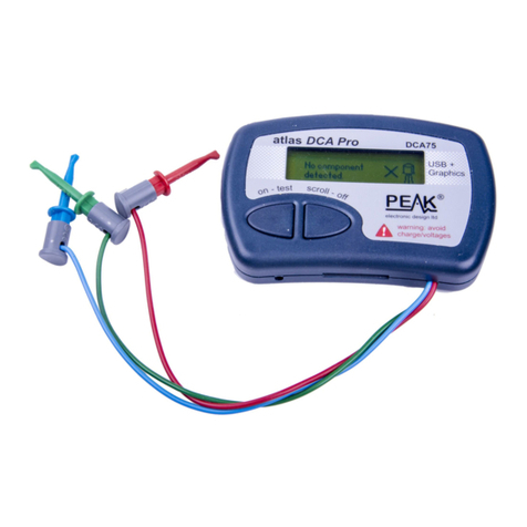
The Peak Atlas DCA Pro is an advanced semiconductor analyser that
combines simplicity, ease of use and a range of advanced features. You can
use your DCA Pro on its own or in combination with a laptop or desktop PC.
Summary Features:
·Automatic component type identification and schematic display:
Bipolar transistors, Darlington transistors and Digital transistors.
Enhancement Mode and Depletion Mode MOSFETs.
Enhancement Mode and Depletion Mode IGBTs.
Junction FETs (including SiC normally off types).
Low power sensitive Triacs and Thyristors.
Light Emitting Diodes including Bicolour LEDs (2 and 3 leads).
Diodes and Diode networks.
Zener diodes (<~11V).
Voltage regulators (<~8V).
·Automatic pinout identification, just connect any way round.
·Special feature identification such as free-wheeling diodes and
resistor shunts.
·Gain measurement for bipolar transistors.
·Leakage current measurement for bipolar transistors.
·Silicon and Germanium detection for bipolar transistors.
·Gate threshold and transconductance measurement for MOSFETs,
JFETs and IGBTs.
·Semiconductor forward voltage measurement for diodes, LEDs and
transistor Base-Emitter junctions.
·Zener voltage measurement.
·Voltage regulator drop-out measurement.
·PC connectivity providing:
Larger component identification display.
Detailed characteristics measurement.
Curve tracing functions.
·Single alkaline AAA cell (not used when USB connected).
·Automatic and manual power-off.
Peak Atlas DCA Pro User Guide October 2022  Rev 1.8
Page 5
Important Considerations
Please observe the following guidelines:
·This instrument must NEVER be connected to powered
equipment/components or equipment/components with any
stored energy (e.g. charged capacitors). Failure to comply with
this warning may result in personal injury, damage to the
equipment under test, damage to your DCA Pro and
invalidation of the manufacturers warranty.
·The DCA Pro is designed to analyse semiconductors that are
not in-circuit, otherwise complex circuit effects will result in
erroneous measurements.
·Large voltage differences between true earth and your PCs
USB port can result in damage. The device under test should
therefore have no path to earth or other supplies.
·Avoid rough treatment, hard knocks and extreme temperatures.
·This unit is not waterproof.
·Only use a good quality AAA Alkaline or Lithium-Iron-
Disulphide cell. Input supply rated up to 1.9V.
Peak Atlas DCA Pro User Guide October 2022  Rev 1.8
Page 6
Analysing Semiconductors  Standalone mode
The DCA Pro is designed to analyse discrete,
unconnected, unpowered components.
This ensures that external connections dont
influence the measured parameters. The three test
probes can be connected to the component any way round.
If the component has only two terminals, then any pair of the three
test probes can be used.
The DCA Pro will start component analysis when the on-test button is
pressed.
For the first analysis, the tests are
performed while displaying the Peak
logo (no time is wasted while
displaying the logo).
For subsequent testing when the unit is
already powered-up, the unit displays
the Testing screen.
Depending on the component type, analysis may take a few seconds to
complete, after which, the results of the analysis are displayed.
Information is displayed a page at a time, each page can be smoothly
scrolled by briefly pressing the scroll-off button.
Although the
DCA Pro
will switch itself off if left unattended, you can
manually switch the unit off by holding down the
scroll-off
button for
a couple of seconds.
s
t
w
a
y
r
o
u
n
d
.
n
y
p
a
i
r
o
f
t
h
e
t
h
r
e
e
Peak Atlas DCA Pro User Guide October 2022  Rev 1.8
Page 7
If the DCA Pro cannot detect any
supported component between any of
the test probes, the following message
will be displayed:
If the component is not a supported
component type, a faulty component or
a component that is being tested in-
circuit, the analysis may result in the
following message being displayed:
Some components may be faulty due
to a shorted junction between a pair of
the probes. If this is the case, the
following message (or similar) will be
displayed:
If all three probes are shorted (or very
low resistance) then the following
message will be displayed:
It is possible that the
DCA Pro
may detect one or more diode junctions
or other component type within an unknown or faulty part. This is
because many semiconductors comprise of PN (diode) junctions.
Please refer to the section on diodes and diode networks for more
information.
Peak Atlas DCA Pro User Guide October 2022  Rev 1.8
Page 8
Diodes
The DCA Pro will analyse almost any type of diode. Any
pair of the three test clips can be connected to the diode, any way
round. If the unit detects a single diode, a message similar to the following
will be displayed:
In this example, the Cathode (symbol
of K) is connected to the Green test
clip and the Anode (symbol of A) is
connected to the Blue test clip,
additionally, the Red test clip is unconnected.
The forward voltage drop is also displayed; this gives an indication of the
diode technology. In this example, it is likely that the diode is a standard
silicon diode. A germanium or Schottky diode may yield a forward voltage of
about 0.25V. The current at which the diode was tested is also displayed.
Unlike most multimeters that dont have a defined diode test current, the
DCA Pro typically tests diodes (PN junctions) at a forward current of 5mA.
You can test at different currents by performing an I/V graph using the PC
software.
Note that the
DCA Pro
will detect only one diode even if two diodes
are connected in series when the third test clip is not connected to the
junction between the diodes. The forward voltage drop displayed
however will be the voltage across the whole series combination.
The
DCA Pro
will determine that the diode(s) under test is an LED if
the measured forward voltage drop exceeds 1.50V. This has no effect
on the readings displayed other than the LED message instead of Diode
message. Please refer to the section on LED analysis for more
information.
o
d
e
.
A
n
y
h
e
d
i
o
d
e
,
a
n
y
w
a
y
Peak Atlas DCA Pro User Guide October 2022  Rev 1.8
Page 9
Zener Diodes
The DCA Pro supports Zener diodes (and Avalanche
diodes). Additionally, the instrument can measure the Zener
voltage*.
Connect any pair of the 3 test leads to the Zener diode. Following analysis, the
component details are displayed.
In this example, a Zener diode with a
reverse voltage (Zener voltage) of
nearly 5.1V has been detected.
Additionally, the forward biased
voltage characteristic is measured,
0.702V at 5mA for this example.
The DCA Pro attempts to test the Zener diode with a current of nominally
5mA. For Zener diodes with a Zener voltage of more than about 7V, a lower
test current of 2mA or 1mA will be used. This is illustrated in the following
graph:
*The DCA Pro may not be able to identify Zener diodes with a Zener voltage
of more than 11V. It will however still identify the diode junction in its
forward biased mode.
v
a
l
a
n
c
h
e
e
a
s
u
r
e
t
h
e
Z
e
n
e
r
Peak Atlas DCA Pro User Guide October 2022  Rev 1.8
Page 10
Diode Networks
The DCA Pro will identify multiple diode junctions
between the probes. For three terminal devices such as
SOT-23 diode networks, all three test clips must be
connected. The optional Peak Component Adapter for SOT-
23 parts (Peak model PCA23) can be useful for testing SOT-23 parts.
The instrument will describe the type
of diode network as text and as a
component schematic symbol. Types
of diode network supported include:
Series pair, Common Cathode and
Common Anode.
It will then show the pinout and the VF
specs for each diode in turn.
It can be seen in this example, that the blue test clip is connected to both the
anode on Diode #1 and to the cathode of Diode #2. This means that the two
diodes are effectively connected in series, with the blue clip at the mid point.
This example is illustrated below:
In the same way as the single diode analysis, the forward voltage for each
diode is measured for a nominal test current of 5mA.
T
-