manuals.online logo
Brands
  1. Home
  2. •
  3. Brands
  4. •
  5. Pearl
  6. •
  7. Music Pedal
  8. •
  9. Pearl P-3002D User manual

Pearl P-3002D User manual

P-3002D
P-3001D
Key Bolt
(for Direct Link
Adjustment)
Direct Link
Beater Setting Stopper
Control Core Beater
Upper Nut
Lower Nut
Click Lock
Wing Bolt
Beater Holder Link
Adjustment Knob
Key Bolt (for Beater
Position Adjustment)
Uni-Lock Footboard
Angle Cam
Key Bolt
(for Footboard
AngleAdjustment)
Traction
Plate
Key Bolt
(for Beater Stroke Adjustment)
Footboard
Traction Grip
Hinge
Heel Plate
Bottom Plate
Multi Function
Drum Key
Long Footboard
Short Footboard
Drive Shaft Drive ShaftCenter
Connecting Tube
Drive Shaft Assembly
Key Bolt
Key Bolt
Instruction Manual
Congratulations on your purchase! To get optimum performance of your
"P-3002D" Drum Pedal, please read this Instruction Manual before playing.
Attachments
Oil, Velcro Tape (x6), Allen Wrench (3mm, 2.5mm)
PEARL DRUM PEDAL
P-3002D
P-3002DL/P-3001D
In the initial factory setting, the
Index Mark is centered in the
Window as shown (Fig. 2).
Index Mark
Initial
Setting
Beater Holder Link
Key Bolt
Beater Stopper
Control Core Beater
Beater Holder Link
Key Bolt
Drum Key
Beater Stopper
Allen Screw
Key Bolt Beater Holder Link
Fig. 2
Fig. 1-B
Fig. 1-A
Fig. 3
Fig. 4-A
Fig. 6
Control Core Beater Setting
Insert the Control Core Beater into the Beater Holder Link
until it stops against the Beater Setting Stopper, and tighten
the Key Bolt with the provided Multi Function Drum Key
(Fig.1-A). Make sure that the Beater Setting Stopper is flush
against the Beater Holder Link with the flat face square
against the Notch (Fig.1-B).
To change to a higher or shorter beater height, loosen the
Allen Screw on the Beater Setting Stopper with the provided
Multi-Function Drum Key or Allen wench (3mm) then loosen
the Key Bolt on the Beater Holder Link (Fig. 3). Set the
beater to the desired height and re-tighten the Key Bolt.
Reset the Beater Setting Stopper flush against the Beater
Holder Link per the instructions above.
Beater Stroke Adjustment
The P-3002D Demon Drive Double Pedal features our
exclusive two-position Beater Holder that can be positioned
closer or further from the drum head for Finesse "A" Position
setting or Power "B" Position setting respectively.
It also rotates infinitely for perfect beater angle without
changing the footboard height.
. Changing the Beater Holder Position
To change to Power setting, loosen the Key Bolt to open the
clamp and slide the Beater Holder to the Power setting
position (Fig.4-A, 4-B). There is no need to remove the Key
Bolt from the clamp.
. Beater Angle Adjustment
To change the angle of the Beater, loosen the Key Bolt and
set the angle to your preference and re-tighten the Key Bolt
(Fig.5).
Fig. 4-B
"B" Position (Power)"A" Position (Finesse)
The Beater Setting Stopper preserves the height setting if the
beater is removed when transporting the pedal.
Indicator marks are provided for referencing beater angle settings
(Fig.6).
Tip
Tip
Tip
Tip
The Beater Holder is set at the factory in the Finesse "A" Position.
Fig. 5
A B
Initial
Setting
Key Bolt
Uni-Lock Footboard Angle Cam
Key Bolt
Drum Key
Heel Plate
Hinge
Hinge
Flat Head Screw
3-Piece Screw
Bottom Plate
Footboard
Fig. 9
Fig. 8-A
Duo-Deck Footboard
The P-3002D features Pearl's patented Duo-Deck Footboard,
the world's first convertible Short / Long Footboard.
To convert the Duo-Deck to a Long Footboard, turn the
pedal over and remove the four Flat Head Screws with the
provided Multi-Function Drum Key or Allen wrench (3mm)
as shown and remove the Heel Plate and the Hinge from the
Bottom Plate (Fig.9).
Lift the Footboard and remove the four 3-Piece Screws with
the provided Multi-Function Drum Key or Allen wrench
(3mm) as shown, and remove the Hinge from the Footboard
(Fig.10).
Direct Link Adjustment
The Direct Link can be adjusted to provide a Heavier or a
Lighter feel.
To change to a Lighter Feel, remove the Key Bolt with the
Multi-Function Drum Key as shown. Move the Direct Link to
the forward set of holes and re-attach the Key Bolt. To change
back to a Heavier Feel, remove the Key Bolt and attach the
Direct Link to the rear set of holes (Fig. 7-A, 7-B).
Footboard Angle Adjustment
The Footboard Angle can be adjusted by loosening the Key
Bolt on the Uni-Lock Footboard Angle Cam and adjusting it
to the desired angle (Fig.8-A). Re-tighten the Key Bolt to
secure the angle. A gauge on the side of the Angle Cam is
provided to reference Footboard Angle settings (Fig.8-B).
Fig. 7-A Fig. 7-B
"L" Position (Lighter Feel)"H" Position (Heavier Feel)
Long FootboardShort Footboard
Fig. 10
Fig. 8-B
Note
Tip
The Direct Link is set at the factory in the Heavier Feel "H" Position.
The Duo-Deck is set at the factory in the Short Footboard setting.
H L
You may need to rotate the Drive Shaft Assembly to bring the
footboard of the Slave side (left) pedal to the proper playing height
(angle) before attaching the Drive Shaft Joints (A) to both pedals.
If the drive shafts are extended too far, they will separate from the
Center Connecting Tube. Reassemble them with the dots aligned
as shown in Fig.15-B.
Connecting the Drive Shaft Assembly
Connect the ends of the Drive shaft (A) to the short
extensions (B) on the Main and Slave side Pedals and
tighten the Key Bolts (Fig.13 , 14).
Loosen the Key Bolts on the Center Connecting Tube of the
Drive Shaft Assembly and adjust the distance between the
Main Pedal and the Slave Side Pedal to your liking.
Re-tighten the Key Bolts (Fig.15-A).
Fig. 13
Fig. 14
Fig. 15-A
Fig. 15-B
A
B
B
Heel Plate
Hinge
Hinge
3-Piece Screw
Flat Head Screw
Flat Head
Screw
3-Piece
Screw
3-Piece Screw
Bottom Plate
Footboard
Reattach the Hinge to the Footboard in the position shown
with two 3-Piece Screws using the provided Multi-Function
drum key or Allen wrench(3mm) (Fig.11).
Place the Heel Plate between the Footboard and the Hinge
(Fig.12) and attach the Heel Plate with the remaining two
3-Piece Screws using the Mutli-Function Drum Key or Allen
wrench (3mm). Attach the Hinge to the Bottom Plate with
the Flat Head Screws using the Multi-Function Drum Key or
Allen wrench (3mm) (Fig.12). The Hinge is now located at
the back of the Footboard to achieve a Long Footboard.
Fig. 11
Fig. 12
The Duo-Deck Footboard uses two
different types of screws. Make sure
to use the correct screws.
Note
Tip
Tip
A
Drive shaft
Drive shaft
Key Bolt
Key Bolt
Upper Nut
Spring
Traction Dot
3-Piece Screw
Traction Plate
Velcro Strips
Allen Screw
Allen Wrench
Adjustment Knob
Wing Bolt
Lower Nut
Click Lock
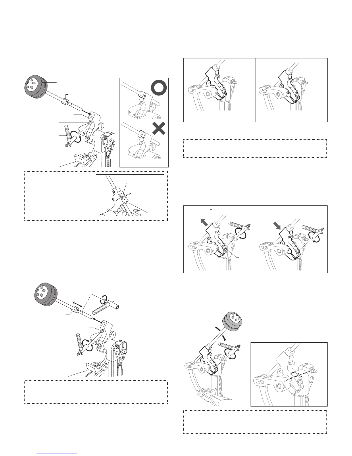
Spring Tension Adjustment
The P-3002D Demon Drive Double Pedal features our
patented Click Lock spring tension retention system. To
increase the spring tension, disable the Click Lock by lifting
the lever upward, loosen the Upper Nut and tighten the
Lower Nut until the desired tension is achieved (Fig.16-A).
To decrease spring tension, disable the Click Lock by lifting
the lever upward, loosen the Upper Nut and loosen the
Lower Nut until the desired tension is achieved. When the
desired spring tension is achieved, tighten the Upper Nut to
keep the spring tension from loosening then press the Click
Lock lever down to engage the grooves around the Lower
Nut until you feel the lever "Click" (Fig.16-B). Before playing,
make sure that both Upper and Lower Nuts are tight and the
Click Lock lever is in a vertical position with both sides of
the lever engaged in the grooves around the Lower Nut.
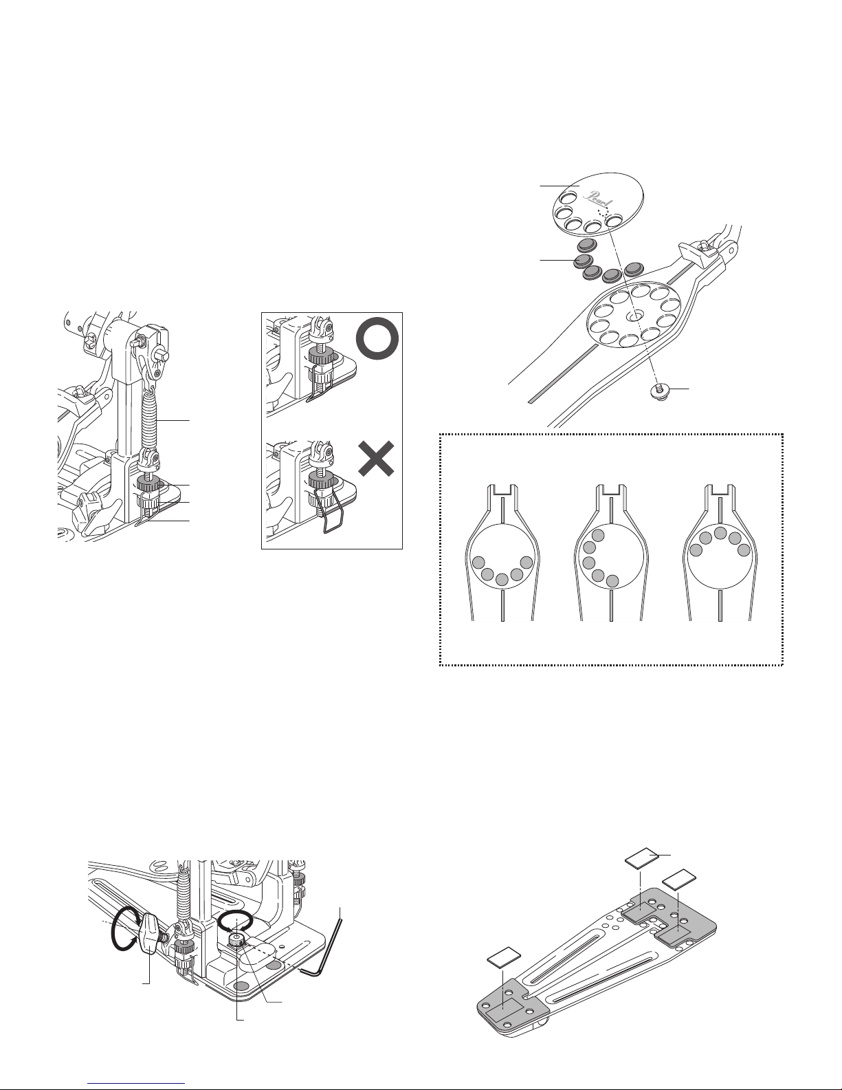
Traction Plate / Traction Dots
The Traction Plate adjusts to a variety of grip/slide
configurations. To change the position of the Traction Dots,
use the Multi-Function Drum Key or Allen wrench (3mm) to
remove the 3-Piece Screw beneath the footboard and
remove the Traction Plate (Fig.19). Rearrange the Traction
Dots to your preference and replace the Traction Plate.
Velcro Strips for Slip Prevention
Velcro Strips are provided with the P-3000D pedal to help
prevent slipping when used on carpeted floors. To apply,
peel off the backing on the Velcro Strips and apply them in
the locations shown. Clean the surfaces thoroughly with
alcohol and dry completely for best adhesion (Fig.20).
Hoop Clamp System
The P-3002D Hoop Clamp System is designed with
Spherical Rubber Grips allowing the front of the bass drum
to be raised while keeping the pedal flush on the floor.
Insert the bass drum hoop into the clamp, and turn the Wing
Bolt to secure.
The clamp comes preset from the factory to accommodate
most bass drum hoops but if necessary it can be adjusted
to fit thicker or thinner hoops. Loosen the Allen Screw on the
Adjustment Knob with the provided Allen wrench (2.5mm)
as shown and tighten or loosen the Adjustment Knob until
proper fit is achieved then re-tighten the Allen Screw
(Fig.18). If the heel plate of the pedal lifts while playing, try
loosening the Adjustment Knob to change the angle of the
Hoop Clamp until the pedal remains flat.
Fig. 17-B
Fig. 19
Fig. 20Fig. 18
Fig. 17-A
Tip
Setting Examples
The Aluminum Traction Dots can be replaced with optional
NP-283N/7 Rubber Dots for more traction.
Slave Side Pedal
Main Pedal
. Converting the Main Pedal
To convert the Main Pedal to a Single Pedal, turn the pedal
over and remove the two Flat Head Screws with the
provided Multi-Function Drum Key or Allen wrench (3mm)
and detach the Hoop Clamp (Fig.21).
Modular Post System
The P-3002D features Pearl’s Modular Post System that
allows easy conversion from one Double Pedal to two Single
Pedals.
Reattach the Hoop Clamp in the position shown with the two
Flat Head Screws using the provided Multi-Function Drum
Key or Allen Wrench (Fig.23). Your main side pedal is ready
to be used as a Single Pedal.
Remove the four Flat Head Screws under the left post with
the provided Multi-Function Drum Key or Allen wrench
(3mm), and detach the Left Post (Fig.22).
Fig. 21
Fig. 22
Fig. 23
Click Lock
Key Bolt
(Uni-Lock
Footboard
Angle Cam)
Dum Key
Spring
Assembly
Lower Nut
Bolt
. Converting the Slave side Pedal
To change the Slave Side of a P-3002D Double Pedal into a
Single Pedal, detach the Spring Assembly and the Beater
Holder Link from the Left Post of the P-3002D Double Pedal
and transfer them to the Slave Side Pedal.
To detach the Spring Assembly, disengage the Click Lock
(Fig.24-a) and remove the Lower Nut (Fig.24-b) and remove
the threaded rod from the post . Loosen the Key Bolt
(Fig.24-c) and remove the Uni-Lock Footboard Angle Cam
from the post (Fig.24-d) . Gently spread the Click Lock
apart and remove it from the post (Fig.24-e) Use caution to
prevent the Click Lock from deforming. To detach the
Beater Holder Link, remove the Key Bolt with the
Multi-Function Dum Key, open the clamp and remove it from
the shaft (Fig.24-f) .
Fig. 24
Beater Holder Link
<a>
<b>
<c>
<f>
<d>
<e>
http://www.pearldrum.com
Products and specifications are subject to change without notice.
Printed in China
-1504-
For best results, always use genuine NiNjA Oil.
Note
Oil
The P-3002D features
precision NiNjA bearings for
incredible speed and
smoothness. To keep them
functioning at their maximum
speed and performance it's
recommended that you
apply genuine NiNjA Oil at
regular intervals (Fig.26).
NiNjA Oil is also ideal for
use on footboard hinges and
Direct Link bearing to
maintain "like-new"
performance (Fig.27, 28).
Fig. 26
Fig. 27
Fig. 28
Check all Key Bolts and Allen Screws for tightness
before performance, and tighten them with the
provided Multi-Function Drum Key or Allen wrenches
as needed.
CAUTION
Reverse the previous
sequence and attach the
Spring Assembly, Beater
Holder Link and the
Beater to the Slave Side
Pedal. Change the
position of the Key Bolt as
shown on the Uni-Lock
Footboard Angle Cam for
easier access when
making Footboard angle
adjustments (Fig.25). Your
Slave Side Pedal is now
ready to be used as a
Single Pedal.
Fig. 25
Optional Items (sold separately)
. Control Core Wood Beater (B-300W)
. Traction Rubber Grip (NP-283N/7)
. Pedal Stabilizer ( PS-300 )
. NiNjA Oil ( OL-300 )

This manual suits for next models

2

Other Pearl Music Pedal manuals

Pearl Demon Drive 3000C Series User manual

Pearl

Pearl Demon Drive 3000C Series User manual

Pearl Eliminator Demon Drive Specification sheet

Pearl

Pearl Eliminator Demon Drive Specification sheet

Pearl P-3000C User manual

Pearl

Pearl P-3000C User manual

Pearl Eliminator Demon Chain User manual

Pearl

Pearl Eliminator Demon Chain User manual

Pearl P-2050C User manual

Pearl

Pearl P-2050C User manual

Pearl P-120 User manual

Pearl

Pearl P-120 User manual

Pearl P-1000 User manual

Pearl

Pearl P-1000 User manual

Pearl Eliminator Demon Drive Specification sheet

Pearl

Pearl Eliminator Demon Drive Specification sheet

Pearl Eliminator Demon Drive P-3002D Installation guide

Pearl

Pearl Eliminator Demon Drive P-3002D Installation guide

Pearl RH-2050 User manual

Pearl

Pearl RH-2050 User manual

Pearl P-2052C User manual

Pearl

Pearl P-2052C User manual

Pearl P-2000C User manual

Pearl

Pearl P-2000C User manual

Popular Music Pedal manuals by other brands

mxr Tremolo M305 quick start guide

mxr

mxr Tremolo M305 quick start guide

Mod THE SUSPENDED CHIME Troubleshooting supplement

Mod

Mod THE SUSPENDED CHIME Troubleshooting supplement

Eagletone COCKTAIL Series quick start guide

Eagletone

Eagletone COCKTAIL Series quick start guide

BYOC Overdrive 2 Kit instructions

BYOC

BYOC Overdrive 2 Kit instructions

Vertex Ultraphonix product manual

Vertex

Vertex Ultraphonix product manual

aion SOMNUS manual

aion

aion SOMNUS manual

Stagg Blaxx operating instructions

Stagg

Stagg Blaxx operating instructions

Duncan Killing Floor user guide

Duncan

Duncan Killing Floor user guide

TC Electronic PLETHORA X3 quick start guide

TC Electronic

TC Electronic PLETHORA X3 quick start guide

Yerasov Red Formica user manual

Yerasov

Yerasov Red Formica user manual

stereophonic FEVER PITCH user manual

stereophonic

stereophonic FEVER PITCH user manual

Electro-Harmonix NEXT STEP SERIES manual

Electro-Harmonix

Electro-Harmonix NEXT STEP SERIES manual

Dusky Mandorla user manual

Dusky

Dusky Mandorla user manual

Voodoo Lab PEDAL POWER DIGITAL user manual

Voodoo Lab

Voodoo Lab PEDAL POWER DIGITAL user manual

Zoom Guitar Effects Console G9.2tt2q Operation manual

Zoom

Zoom Guitar Effects Console G9.2tt2q Operation manual

FAME Chorus LEF-304 user manual

FAME

FAME Chorus LEF-304 user manual

Source Audio Reflex user guide

Source Audio

Source Audio Reflex user guide

TC Electronic HALL OF FAME 2 X4 REVERB user manual

TC Electronic

TC Electronic HALL OF FAME 2 X4 REVERB user manual

manuals.online logo
manuals.online logoBrands
  • About & Mission
  • Contact us
  • Privacy Policy
  • Terms and Conditions

Copyright 2025 Manuals.Online. All Rights Reserved.