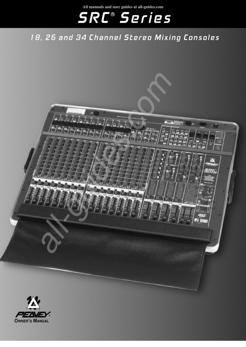
Peavey SRC 421-16 User manual

OWNERS
MANUAL
SRC
421
16/24
SOUND
REINFORCEMENT
CONSOLE
WARNING;
TO
PREVENT
ELECTRICAL
SHOCK
OR
FIRE
HAZARD,
DO
NOT
EXPOSE
THIS
APPLIANCE
TO
RAIN
OR
MOISTURE.
BEFORE
USING
THIS
APPLIANCE,
READ
THE
OPERATINC
GUIDE
FOR
FURTHER
WARNINGS.


CHANNEL
SECTION.
There
wll
be
eliher
ie
charnels
on
Model
SRCT
421-16.
or
24
channels
cn
Model
SRC*
421*24.
QAIN
(1|
Vanee
the
^ein
the
channef
mpi/t
stage
to
allow
a
wide
input
dynamic
range.
Proper
adjustment
of
the
input
s^'n
la
aided
by
observance
of
the
LIMIT
LED.
HICH(2}
An
active
lone
conirol
(shelving
type,
±15
dB)
that
varies
the
high
frequercy
booet
or
cut,
MID/FnEQUENCY
(3}
The
(inner)
"MID*
is
an
active
control
capable
of
15
dB
of
txxjst
or
cut
at
the
center
frequency
selected
by
the
(cuter)
’FREQUENCY"
control.
Frequo,ncy
range
Is
variable
Tom
200
Hz
to
5
kHz
LOW
(4)
An
aclive
icrie
control
(shelving
type,
±15
OB)
that
varies
the
low
freguercv
boost
or
cut.
OPERATION
NOTE
Excessive
EQ
boost,
especially
of
the
low
frequencies,
rrcreases
the
possibtjity
of
speaker
damage,
and
sacrcfces
valuable
head¬
room
AUX.
CONTROL
and
PHE/POST
BUTTON
(5)
The
AUX.
control
regulates
the
amount
of
signal
routed
to
the
AUX.
Master
(xmtol
The
PREyPOST
button
will
choose
whether
the
AUX.
6<gnaJ
i
s
take
n
from
the
PR
E-
EQ
{button
up),
or
the
PO
ST-EQ
{button
down).
EFX.
SEND
A/B
(6)
Two
effects
sends
are
c^o^ed
in
aduaJ-concentric
control.
The
Imer
knob
is
EFX.
A;
the
outer
isEFX
S.
&ot\
sends
are
Post
(after)
EQ,
and
Post
Fader.
The’A*
send
supplies
tne
EFX
.A
master
conirol;
the
B'
send
supplies
the
EFX.
B
master
contrd.
PFL
(7)
Allows
cueing
of
any
channel
or
combination
of
channels
instantly
through
headphones
connected
to
the
headphone
lack
(master
section).
A
It
c^nan
nol
function
s
(except
fad
e
f)
may
be
monitored
v<
a
ins
channef
PFL
system
LIMIT
LED
(8)
Indicales
when
the
signal
level
in
the
channel
«
too
high.
It
Illuminates
when
the
channel
slgri^
reaches
approximately
+15
dBV,
OPERATION
NOTE
ItIumtnaJion
indicates
clipping
(dfsrortion)
m
the
channel.
Proper
channel
adjustment
wilt
allow
operation
without
lighting
the
LEO.
Adjust
the
Gam,
EQ
and
Level
so
that
the
LED
doas
not
flash
dunng
cperalion.
The
sampling
lot
status
inGication
istaken
at
three
onticaJ
points;
after
the
input
amp
and
Out/In
mserison
point,
equalization,
end
fine)
channel
gan
stage.
CHANNEL
LEVEL
FADER
(9)
Determines
the
level
of
the
channel.
Calibration
is
tn
dBand
level
is
variab
le
I
rom
-
i
nfini
ty
(off)
to
+10
d
8,
This
sh
ould
be
operated
near
me
“0
d8"
(unity
gan)
indicator
wherever
pceslble
to
assure
an
optimum
baJance
between
channel
noise
and
headroom.
OPERATION
NOTE
it
may
be
necessary
to
operate
the
Chanel
Level
Fadsr
at
other
man
ih©
optimum
setting.
Example-
If
me
channel
need
not
be
as
loud
as
the
other
channels,
the
Fader
may
bo
set
lower
than
0
dB,
This
yields
lower
noise
^d
a
visual
indicabon
of
the
channel's
refanve
level.
Should
rrcfs
level
be
needed,
ii
can
be
achieved
with
me
Fader,
prevenUng
re
adjustment
of
the
critical
input
gam,
which
would
also
affect
the
AUX,
Send.
PAN
(10)
For
stereo
operation
PAN
is
used
to
mix
iha
channel
output
to
lefL
rtg
h
I,
or
I
n
b
etwe
en
i
n
the'
s
tereo
imag
e*.
Fo
r
mo
no
or
submastori
ng
operation,
the
PAN
control
is
used
with
the
assignment
switches
to
pan
The
channel
output
between
Submasiers
1
or
2
when
ihe
1-2
b
utton
is
pressed,
Submaete
rs
3
or
4
when
me
3-4
b
utton
is
pressed,
and
direct
to
L
or
R
when
the
L-R
button
is
pressed.
ASSIGNMENT
SWITCH
L^R
(11)
Wher
depressed,
this
button
allov/s
the
channel
to
send
its
output
th
roug
n
the
PAN
c
ont
rol,
whi
ch
wi
l(
rtow
'
c
rosstade*
be
twee
n
Ou
tput
Masters
LefI
and
Right.
With
this
furtotion
engaged.
Pen
control
L
position
directs
output
to
the
L^t
Output
Master,
center
po&don
will
output
to
both
Masters
equally,
and
in
me
R
position
the
outotJt
will
be
sent
to
Ihe
Right
Ou
tout
Waste'.
ASSIGNMENT
SWITCH
1*2
(12)
When
depressed,
this
button
allows
the
channel
to
send
its
output
through
the
PAN
conirol,
which
will
now'crosslade'
between
Sub-
masters
1
and
2
With
this
tuncaon
engaged,
Pan
control
Lpesition
directs
output
to
Submaster
1,
center
position
wiP
output
to
both
submasters
equally,
and
in
the
R
position
the
output
will
be
sent
to
SubrriastDr
2,
ASSIGNMENT
SWITCH
3*4
[13)
When
depressed,
Thte
button
allowe
the
charnel
to
serid
rts
output
through
the
PAN
control,
which
will
now
‘crosslade’
between
Sub-
masters
3
and
4.
With
this
fuhCTlon
er^gaged,
Pan
conrroi
L
position
directs
output
to
Submasier
3.
center
position
will
cutout
to
both
Su
b
masters
eq
u
ally,
and
I
n
the
R
position
i
he
output
wi
11
be
sent
to
Submaster
4,
OPERATION
NOTE;
This
assignment
system
provides
4
Mono
Submasters
which
oar
ba
assigned
to
L
and
R
by
the
Sub
Pan
control.
For
2
Stereo
Sub
mas¬
ters,
group
Subs
1,
2
and
Subs
3,
4
together,
and
par
Sub
Pan
1
and
3
to
L,
and
Sub
Pan
2
and
4
to
R.
The
Channel
can
then
be
assignea
fo
the
1-2
stereo
Submaster
by
pressing
the
i
-2
button,
to
the
3-4
stereo
Submaster
by
pressing
the
3-4
button,
or
direct
lo
L
and
R
by
pressing
the
L-R
button.
The
channel
Pan
control
is
then
used
to
piacs
the
channel
tn
the
desired
position
wlihin
the
'stereo*
image.

MASTER
SECTION
EFFECTS
RETURN
SECTION
SUB
1/AUX
ARRAY
(14]
A
caliDraied,
switch*
59
ieciable
LED
array
is
provided
!o
visaalJy
d
icat©
th
©
ouTpjt
I
av
si
of
S
j
D
1
or
Au
x.
Switch
Ou
i
posi
Jior
sel
eels
Sub
1,
Switch
In
position
eeteote
Aux.
SUB
2/PFL
ARRAY
[15]
A
caliorated,
switch-selectable
LED
array
is
provided
to
visually
indicaieth
6
outpuilev
0
iO'fSjD
2
orPFL.
SwitenOOt
position
ssiecte
Sub
2;
Switch
In
position
selecis
PFL,
SUB
3/LEPT
ARRAY
(16)
A
calibrated,
switeh-seleotaoie
LED
array
is
provided
to
visually
indicate
the
output
®vel
of
Sub
3
or
Left
Mam.
Swteh
Out
position
selects
Sub
3;
Switch
In
posuion
selects
Left
Main.
SUB
4/niCKT
MAIN
ARRAY
|17)
A
caJibrated.
swiich-selacjabie
LED
Sfray
is
provided
lo
visually
indicate
the
output
level
of
Sub
4
or
Right.
Switch
Out
position
selects
Sub
4;
Switch
In
position
seleota
Right
Main.
EFFECTS
“A’*
RETURN
SECTION
NOTE:
This
has
an
tnle
m
ai
ly
pare
hed
Rave
rb
vrfnich
is
auro
malic
al
ly
removed
from
the
signal
path
when
a
plug
is
inserted
inW
the
EFX.
A
raium
|ack.
EFX.
A
TO
AUX.
(18)
Allows
the
'
A'
Efleci
id
be
assigned
to
the
Aux
Mix.
LEVEL/PAN
Lm
[18]
DuaJ
cortcentftc
control:
The
outer
knob
Is
a
stereo
Pan
control
for
Effects
’A’
return
assignment
loL
S
R
or
Subs
1,2,
3,
and
4.
Must
be
used
In
conjunction
with
assignment
switches
21
thru
23.
The
inner
knob
controls
\ha
level
of
the
Effects
"A"
Return
When
an
cutboard
effects
device
is
patched
into
the
Effects
"A*
patch
loop,
!^s
control
determines
rhe
level
ol
he
effect
that
is
routed
thru
the
Effects
"A*
Pan
control.
PPL
(20}
The
''Irt"
position
of
this
switch
assigns
the
Effects
'A*
Return
lo
PFL.
(See
19.)
L
•
R
ASSIGN
(21)
The
"In*
posictof^
of
this
switch
routes
the
Effects
"A*
Return
thru
Etecis
"A‘
Pan
comroi
directly
10
left,
right
or
both.
The
“Oui*
posiliem
removes
Effect
'A'
from
L
and
R.
1
.
2
(
22
)
The
"In*
position
of
this
switch
routes
the
Effects
“A"
Return
thru
Effects
"A'
Pan
comroi
to
Sub
1.
Sub
2.
or
beth.
The
"Out*
position
removes
Effect
“A"
from
Subs
1
and
2.
3
•
4
(23)
The
"In*
position
of
this
switch
routes
the
Effects
'‘A“
Return
thru
Effects
"A*
Pan
ccnlrol
to
Sub
3.
Sub
4.
or
both.
The
*Out*
posi^on
removes
Effect
"A“
from
Subs
3
and
4.
EFX.
B
TO
AUX.
(24)
Allows
the
"B"
Effect
lo
be
assigned
to
the
Aux
Mix.
LEVEUPAN
L/R
(26)
Du^
concentre
control:
The
outer
knob
is
a
stereo
Pan
cont'ol
for
Effecte
"8*
return
aes'gnmentto
L&
R,
orSubs
i,
2,
3,
and
4.
Must
be
used
in
conjunction
wth
assignment
swiches
27
thru
29.
The
inner
knob
controls
the
level
ol
Ihe
Effects
"0*
Return.
When
an
outboard
effects
device
is
patched
into
the
Effects
B*
petch
loop,
tiisconfroi
determines
the
level
of
theeffectfrietis
routed
thru
the
Effects
“B"
Pan
control.
PFL
(26)
Th©
"In*
pcenion
of
this
switch
assigns
th©
Effects
'B*
Return
to
PFL,
(See2&)
L
.
R
ASSIGN
(27)
The
"in"
position
of
this
ewiioh
route©
the
Effect©
*B‘
Return
thru
Effects
*B’
Pan
control
directly
to
left
nght
or
both.
The
“Out"
position
removes
Effect
*B*
frem
L
end
R,
1
•
2
(28)
The
‘In'
position
of
tNs
switch
routes
the
Ettecis
’B'
Return
thru
Effects
"B“
Pan
control
to
Sub
1,
Sub
2.
or
both.
Th©
"Out*
position
'©moves
Effect
‘B’
from
Subs
^
and
2
3
•
4
(29)
Th©
'In'
position
of
this
switch
routes
the
Effects
“B*
Return
thru
Effects
"B"
Pan
control
to
Sub
3,
Sub
4,
or
both.
The
‘Out*
posciori
removes
Effect
'B'
from
Subs
3
and
4
AUX.
MASTER
SUBSECTION
AUX.
MASTER
LEVEL
(30)
Cantroletheovdrali
Aux
Mix
level
appearing
atthe
Aux.
output
lack
AUX
PFL
(31)
Tne
"In"
position
of
tNs
switch
assigns
th©
Aux,
output
to
the
PFL.
EFX.
MASTER
SUBSECTION
EFX.
MASTER
(32)
These
are
Ihe
master
level
conirote
for
the
final
stages
of
effects
dnve.
T
hey
are
d
uaJ
c
0
ncentn
c
conto
Is
•
inner
i
s
the
EFX
A
master
levs)
con
trol,
outer
i
s
th
e
EFX.
B
m
aste
r
leve
I
control.
The
si
g
naJ
may
be
routed
to
PFL
by
pressing
in
Dutton
33
for
EFX.
‘A',
and
butten
34
for
EFX.
"S';
EFX.
A
Master
drives
Ihe
mternai
reverb
system.
PFL
A
(33)
The
"In"
position
of
thisswitch
assigns
Effects
"A"
oulpultoth©
PFL.
PFL
B
(34}
The'ln"
position
of
this
switch
assjgnsEffecis
"B’oulDutlothePFL.

SUBMASTER
SECTION
SUB
1
(35]
Thie
Fader
$etd
tha
lava*
ot
Submaeter
1.
PAN
(36)
For
sereo
operalion,
PAN
is
used
to
'cros5iade‘
the
Submaster
to
the
centef,
letter
rfghi
In
the
L-R'stereo
image*
For
monoepersuion.
PAN
assigne
ine
Submaster
output
to
the
1*
or’R'
Masters.
SUB
2
[37)
This
Fader
sets
the
level
of
Submaster
2.
PAN
(35)
For
etoreo
operahort,
PAN
is
used
to
'crossfade*
the
Submaster
to
tn
e
center.
I
eft
or
right
i
n
rh
e
L-R'
stereo
image'.
For
mon
o
eperetion,
PAN
assigns
the
Submaster
output
to
the
U
or
'R
Masters.
SUB
3
(39)
This
Fador
sets
the
level
of
Submaeter
3.
PAN
(40)
For
stereo
operation,
PAN
is
used
to
'crosslade'
the
Submaster
to
the
centerjettor
right
in
tfie
L*R'stereo
image*.
For
mono
operation,
PAN
as6igr>3
tr^e
Submaeter
output
to
the
'L'
or
'R'
Masters.
SUB
4(41)
This
Fader
sets
the
level
of
Submester
4,
PAN
(42)
For
stereo
operation,
PAN
is
used
to
'crossfade'
the
Sub
master
to
the
center,
left
cr
right
in
the
L-fl'stereo
mage'.
Far
mono
operation.
PAN
assign
5
the
Sub
master
output
to
the
'L*
or*R'
Masters.
MISCELLANEOUS
FUNCTIONS
LAMP
(44)
A
2-pin
XLR
lack
is
provided
for
conneciine
an
optional
gooseneck
mixer
lamp
(Model
ML-2)for
iHummtion
in
adverse
I
ghting
condi-
tiw^.
STEREO
OUT
(45)
Adjusts
the
Left
and
Right
sigr^l
level
lo
the
STEREO
OUT
jack
Sgnais
are
taken
before
<Pre)
the
LEFT
and
RIGHT
Main
Ccnirols
MASTER
(46)
Controls
the
overall
mix
level
when
the
mixer
isoperaled
m
the
rrcito
canffguration
(4x2x1).
MASTER
is
the
combi
nation
of
(he
Wain
LEFT
and
RIGHT
signals
and
the
MASTER
AUX.
In.
PFL
LEVEL
AND
PPL
LED
(47)
Control
s
ih
e
leve
I
fo
r
an
y
“
ore
fade
l
is
ten'
(PFL)
source.
se
lected
on
the
mixer,
and
sands
this
signal
to
the
headphones.
One
or
more
PFL
switch
es
must
be
e
ngag
ed
fc
ef
o
re
Ihts
centred
is
active.
PFL
LE
D
ndicaies
when
the
PFL
is
active.
NOTE:
When
the
PFL(S
active,
it
ove'rides
Stereo
in
the
headphones.
HEADPHONE
LEVEL
(48)
Ad]
usts
the
leve)
of
UR
$
i
gnais
at
th
s
HEADPHO
NE
jack,
u
n
less
the
PFL
signal
is
present.
HEADPHONE
JACK
(49^
This
stereo
jack
allows
signal
to
flow
to
both
scies
ot
any
stereo
headset.
Tip
■
Left,
Ring
■
Right
LEFT/RIQHT
(50)
These
ere
the
Master
Faders
for
all
channels
and
Subrnasters
and
determine
the
overall
main
or
'’housa*
mix
levels.
POWER
SWITCH
(43)
Depress
the
switch
tc
the
"On”
position.
The
red
pilot
light
(LED)
wll
illuminate
indicatsng
power
is
be^ng
supplied
lo
the
unit.

MASTER
PATCH
wksrrH
RkGWT
RIGHT
SECTION
RIGHT
AUX.
IN
(5i)
An
input
to
the
RIGHT
MASTER
for
patching
in
signals
^rom
external
devices
such
as
effects
processors,
or
adding
channels
from
a
second
mixer.
RIGHT
OUTPUT
(52)
An
output
from
the
RIGHT
MASTER
for
patchir>g
signals
out
to
external
devices
such
as
effects
processors,
graphic
equalizers,
power
amplifiers,
etc.
RIGHT
LINE
IN
(53)
A
line
level
input
lo
the
Right
Line
Amplifier
for
patching
in
signals
before
the
balanced
output.
This
input
jack
isewitching
and
may
be
used
for
"In
Line’'
loop
capability
in
conjunction
with
the
right
lin©
output
An
extern
al
signaJ
pate
h
ed
i
n
at
t
hi
s
po
ml
may
u
li
\\ze
ih
e
rig
ht
line
driver
stag©
and
the
XLR
balanced
outt^ut
NOTE:
The
insertion
of
a
1/4*
phone
plug
at
this
point
removes
the
Palarxoed
output
capability
from
the
right
main,
via
the
switching
jack.
RIGHT
BALANCED
OUT
(54)
A
balanced
line
output
containing
the
RIGHT
OUTPUT
signal.
The
signal
level
at
this
output
i3
conirolled
by
the
right
master
slider,
u
niess
th
e
'Rig
ht
Li
ne
Inpu
t*
swi
tching
j
ack
has
bee
n
activated.
This
balanced
output
may
be
used
to
balance
other
signals
which
may
Pe
patched
In
at
the
RIGHT
LINE
INPUT,
(See
Right
Line
In.
53.)
LEFT
SECTION
LEFT
AUX.
IN
(55)
An
input
to
the
LEFT
MASTER
for
patching
in
signals
from
external
devices
such
as
effects
processors,
or
adding
channels
frorn
a
second
mixer
LEFT
OUTPUT
(55)
An
output
from
the
LEFT
MASTER
for
patching
signals
outtoexternai
devices
such
as
effects
processors,
graphic
equalizers,
power
amplllierg,
etc.
LEFT
LINE
IN
(57)
A
lin©
level
input
to
the
Lett
Line
Amplifier
for
patching
in
signals
be
fore
th
e
b
alanced
outp
u
t.
Th
is
input
jack
is
swi
tc
hm
g
and
m
ay
be
used
lor
"In
Line'
loop
capability
in
conjunction
with
the
left
line
output.
An
external
signal
patched
in
al
this
point
may
utilize
the
left
I
i
ne
d
n
ver
stag
e
and
th
e
XLR
bal
a
r^ced
ou
iput,
NOT
E;
Th©
m
se
rtion
of
a
1/4*
phone
plug
al
this
point
r©moves
ihe
balanced
output
capability
from
the
left
mam,
via
the
switching
jack.
LEFT
BALANCED
OUT
(58)
A
balanced
line
output
containing
the
LEFT
OUTPUT
signal.
The
sig
n
all
eve
I
at
th
I
s
0
uiput
Is
contra
11
ed
by
the
I
eft
master
s
I
ide
r,
u
niess
the
"Left
Line
Input"
switching
jack
has
been
activaied.
This
bal¬
anced
output
may
be
used
to
balance
other
signals
which
may
be
patched
In
at
the
LEFT
LINE
INPUT.
(See
Left
Line
In,
57.)
AUX.
SECTION
AUX.
AUX.
IN
(59)
An
Input
for
patching
©xternaJ
signals
into
the
AUX
mixing
bus.
When
conneciing
more
than
one
mixer
for
additional
channels,
The
AUX.
orMonitor
output
from
theseconO
mixer
should
normally
paich
in
at
this
point
AUX.
OUTPUT
(60)
An
output
from
the
AUX,
mixing
bus
for
patching
signals
out
to
external
devices
such
as
power
amplifiers,
graphic
equalizers,
etc.
The
AUX.
Output
is
normally
used
for
a
separate
monitor
mix.
When
the
channel's
AUX.
sends
are
operated
m
'Pre’
position,
the
AUX.
Output
is
notalfected
by
channel
EQ.
The
“POST*
position
allows
channel
EO
to
become
operational
on
AUX,
output.
(See
AUX.
Control
and
Pre/Posi,
5.)
AUX.
LINE
IN
(61)
A
line
level
input
to
the
AUX.
Line
Amplifier
for
patching
in
signals
before
the
balanced
output.
This
input
jack
is
switching
and
may
be
used
for
"In
Line'
loop
capability
in
conjunction
with
the
AUX.
line
output
Any
external
signal
patched
in
at
this
pDinimay
utilize
the
AUX.
lin©
driver
stage
and
the
XLR
balanced
output.
NOTE'
The
insertion
of
a
1/4*
phone
plug
at
this
point
removes
the
balanced
output
capability
from
th©
AUX.
bus,
via
the
switching
jack.

AUX.
BAL.
OUT
(62)
A
balanced
line
otitpjt
ccntainirig
the
AUX,
output
eignal.
The
signal
level
at
this
q
utp
ut
is
control
led
by
I
he
AUX
rrasier
level.
un
less
th
e
''AUX
Line
Input'switcNHQ
jack
has
been
actvated
This
balanced
Q
utput
may
b
a
used
to
baJance
other
eig
nale
wh
ich
may
be
patched
in
^
the
AUX.
Line
Input.
(See
AUX
Line
In,
$1)
MASTER
SECTION
MASTER
AUX.
IN
(63)
An
i
n
put
lo
the
Master
for
patch
i
ng
in
si
g
nals
from
e
rte^nal
dev
ices
such
as
effects
processors
cf
aOding
channels
from
a
second
mixer.
MASTER
OUTPUT
(64)
Ths
oulput
is
a
"Mono'
combination
of
the
left
and
right
program
material.
The
signal
level
at
this
oulput
ts
determined
Dy
the
master
level
oontrcl.
May
be
used
to
drive
external
devices
such
as
power
amps,
graphic
eoualiiers.
effects
processors,
etc.
MASTER
LINE
IN
(65)
A
line
level
input
to
The
Master
I
me
amplifier
for
patching
In&gnals
before
the
balanceo
oulput.
This
input
lack
isswiiching
and
may
b©
used
for
Tn
Line'
loop
capability
in
cortjurtclion
with
master
line
output
Any
external
signal
patched
in
^
this
point
may
utilize
the
.Tester
line
dnvar
stage
and
the
XLR
batancea
oulput,
NOTE:
The
risenion
of
a
1/4'
phone
plug
at
this
point
removes
the
balanced
output
capab'My
from
the
master,
via
the
switching
jack.
MASTER
BAL.
OUT
(66)
A
balanced
ime
output
containing
the
Master
“mono’
output
eign^.
The
sig/Tal
level
at
this
output
is
determined
by
the
master
level
control,
unless
the
'MASTER
Line
Input’
switching
jack
has
been
activated-
This
balanced
output
may
be
used
to
balance
other
signals
which
may
be
patched
in
at
the
Master
Lin©
Input.
(Sea
MASTER
Line
In,
K)
SUBMASTER
SECTION
SUBMASTER
AUX.
INPUTS
(67)
Those
inputs
may
be
used
to
paten
an
external
signal
into
any
of
tne
four
submix
buses
Aix<.
inputs
are
normally
used
forconnectng
a
second
mixer
for
additional
chani*»el5.
SU6MASTER
SEND
6
(66)
These
sends
provide
outputs
from
all
tour
Submasiers
to
drive
ex'ernai
devices
such
as
etfecis
proceseora,
tape
recorder
inputs,
graphe
equalizers,
etc.
The
signs)
level
at
the
“Sub
Sends*
is
determined
by
the
Submaaiersliders,
1
friruA.
Submaslersendsare
normally
used
as
The
output
for
an
independent
effects
loop
on
a
particular
sub
group,
or
to
supply
an
unbalanced
output
To
tape
deck
inputs.
(See
SUB
Returns,
6$-)
SUB.
4,
3,
2
and
1
RETURN
(66)
The
sub
returns
a
re
switching
in
puts
and
rout©
signals
patched
mat
this
point
directly
to
the
Submasler
PAN
controls.
The
sub
returns
are
normaliv
used
to
corripiets
:he
effects
patch
loop
for
signal
p'oc
esei
ng
of
i
no
Mdu
al
S
ubmasters,
(See
SU
8
S
E
N
DS,
68.)
NOTE:
The
sub
return
patch
point
Is
“after*
the
Suomaster
slider
and
'before"
the
Submaster
pan
contrcL
EFX.
A
SECTION
EPX.ASEND
(70}
The
output
from
file
combinaiicn
of
EFX.
A
charmel
SENDS
and
the
EFX,
A
MASTER
Control.
This
effects
send
is
ncmially
i^ed
to
drive
external
effects
processors
controlled
by
the
A
Bus,
and
is
the
output
ocfiion
of
the
"A“
effects
loop.
(See
EFX,
A
Return.
71.)
EPX.
A
RETURN
(71)
A
81
gnal
pate
hed
into
the
E^.
A
Return
i
np
ut
i
s
routed
dire
ctly
to
th
e
EFX.
A
level
control,
compleling
the
"A*
effects
loop.
(See
EFX.
A
Send
7D)
file
EFX.
Return
jack
Is
normally
used
for
the
output
from
external
effects
devices
controlled
by
the
EFX.
A
bus.
NOTE'
The
E
FX.
jack
18
ewitc
h
rng
and
wh
en
a
1
/4'
phen
a
plug
is
pate
he
d
i
n
at
thie
point,
the
internal
reverb
eyatem
ia
disabled
EFX.
B
SECTION
EFX.
B
SEND
(72)
The
output
from
the
eombinaror
of
EFX
B
channel
SEND
and
the
EFX.
6
MASTER
Ccnlrol
This
effects
send
is
normally
used
to
drive
external
effects
processors
controlled
by
the
EFX.
Bus,
end
is
the
output
portion
of
the
*B*
effects
loop.
(See
EFX.
B
Return,
73.)
When
e
xte
rnal
effects
devices
are
not
em
ployed.
th
e
EFX.
B
Send
may
be
uaed
as
aeeparate
recording
mx,
or
to
drive
addtional
power
amp/
speaker
combinationd.
EFX.
D
RETURN
(73)
A
signal
pate
hed
i
nte
the
EFX
B
Return
i
nput
i
s
routed
dire
ctly
to
th
e
EFX.
B
level
cor\tfol.
completing
the
"B*
effects
loop.
(See
EFX.
6
Sen
d,
72.)
The
EFX.
Ratu
m
jack
i
s
normal
ly
used
for
the
o
utput
from
external
effects
devices
controlled
by
the
EFX,
B
bus.
STEREO
SECTION
STEREO
OUT
(74)
A
stereo
(L
and
R)
output
is
forovidea
fer
driving
externa)
devices
such
as
stereo
tape
recorders,
stereo
equalizers,
stereo
power
ampiifiefs,
etc.
The
signal
level
at
the
stereo
out
jack
is
determined
by
the
stereo
cut
level
control.
NOTE;
Stereo
1/4*
plugs
used
to
eccese
the
ST
E
REO
0
UT
sign
al
sh
ou
id
be
wi
red
Tip.«left
and
R
ing
»
right.
PFL
SECTION
PFL
AUX.
(75)
A
etereo
jack
for
patching
two
PFL
buses
together
from
mixer
to
mixer.
Tip
«
PFL
Audio
Signal
Ring
«
PFL
Switching
Control
Signal,
and
grounding
the
sleeve
actives
the
PFL
System.
PHANTOM
POWER
SECTION
PHANTOM
POWER
ON/OFF
(76)
This
switch
seiscte
43V
DC
phantom
power
for
all
channels.
In
the
'*Off"
position,
no
phantom
powering
ia
available
on
any
channels.

CHANNEL
PATCH
SECTION
NOTE
:
These
facIliOeB
are
QuDllcaled
on
every
channel.
PATCH
POST
(77)
A
posi-EQ.
post*Fader
send
and
return
patch
This
uses
a
stereo
jack
Tip
is
send,
and
ring
is
relum.
I
r%depen
dent
channel
output
may
be
accessso
oy
mono
jack
inserted
to
the
fjrst
“cItcK*
PATCH
PBE
(78)
A
pre-EQ
and
level
eend/returr^
patch.
Th<s
uses
a
stereo
jack.
Tip
IS
send,
and
nng
is
relum.
LOW
Z
IN
(79)
For
use
vvith
low
Impedance
microphones
or
low
level
sources
equipped
with
an
XLR
comector.
LINE
IN
(80)
Input
For
use
wih
I
Ins
level
sources
eq
u'
p
ped
wi
fri
an
1
lA*
connector,
SRC
SPECIFICATIONS
All
jfecliKadonsare
tyocal
unless
otherwise
rcied,
fti*)d
are
lefej^.nced
io
ncwiinal
output
l«vei
(OdBV)
unless
orhervriss
rtcAed.
rnea&urftnwnis
sre
widecano
2*3
Hz
x
20
kHz
unless
o;hervr<se
stand.
ooev
«1
Volt
OOBa-
.770
Vo!i
CHANNEL
equivalent
Input
Noise:
.
133
daV
{1
&0
Ohm,
C
,
SO
dB
Gain)
FraquwKy
Response;
S
2
dB
20-20.0CO
Hz
all
EQ
Flat
Distort
«n:
Lessdian
.05%
OdB
Output
80
dBOain
Typioel
003%
^
dB
CUtpul
30
dQ
Gan
jMic
inpui
10
L
cy
R
cuipuB.
EO
flat,
S^ddi^
aiO)
Cenmen
Mode
Rojeelion
Ratio
<ChiRR)
Greater
than
100
dB
typical
Input
Impedance
Mcs
3K
Ohms
Lins
.dOKOhms
Pte
Return
a
20K
onrrs
Post
Re:um
«
2K
Otsna
OOput
Impedance;
Pre
Send
»100
Ohrris
Pcsi
Sane
«100
Ohms
Hi^h
EQ:
e
15
dB
9
10 kHi
Kinmum
Cer
ter
Deism
fM(±2ad
Mid
EQ
xl6
dB
@
Selected
Frequervey
Mid
FreQuenoy:
200
Kz
k>
5
>Hz
adjustment
cl
Mi
d
FrequerKy
Low
EQ;
115
OB
@
50
Hz
Minimum
Center
Detent
Rat
£
2
eB
Uanmum
Preamp
Gen'
80
dB
Vtnimum
Unlmum
PreampGam;
2
dB
MaxIrrafTt
Channel
Gan:
70
dB
(Per
ai
L
or
R,
Stider^
M«,
EOflat)
Maafmurn
tnpm
Level:
Mom
•18d0V<6.5VRMS)
Llrve
•
•r3edBV{60
VRMS)
Pte
Datum
»
*18
dBV
(8
VRMS)
Post
Return
B
*
ifi
dBV
(d
VRM3)
Maximum
Output
Level;
Pre
Send
•
-18
dBV
(8
VSUSf
Post
Send
■
«>TB
dEV
(E
VRMS)
Nominal
hput
Level.
Mk:»
•20dQV(lOO
mV.-13dBu)
Line
»
0
eBV
{1
VRMS)
Pro
Return
sOOBVllCVRM$)
Post
ReluinsOdBV(1.0
VRMB)
Heasrooir;
NomlreU
iSdBV
Ded
LED.SdBV
Pan
Charaoenstics:
2
dB
Dovm
^
^Cd
Positer
LED
Level;
Red
a
«15
dBV
(S.SZVRUS)
MASTER*
LEO
Irteet
Csibration:
0.0
dBV
(1.0
VRMS)
Nominal
Output
Level
Unbalanced'
Master.
»
•0<BV
(iO
VRMS)
LAR.
^dBVIiOVRUS)
Aumery
»
.H3
daV(i
0
VRMS)
Erfeas
a
&
B
■
*0
QBV
(1.0
VRMS)
Nominal
Cupu:
Level
Bataneed:
Master
.
.8
dSV
(SO
VRU5)
L&R«*tO(eV{2.0VRMS)
Au^siiary.-tOdBV
(2.0
VRMS)
Nomine)
Headroom;
Master
a
19
06
iBaisnced
ana
UnCaiancedi
L
8
R
a
19
dB
(Balanced
and
Unbalarcec)
Auxiliay
e
19
dB
(Balanced
and
UribelEtr>ced)
ElfectsA&fiaiOdB
Max'fnurr
Cuipui
Level
Unpatanced.
Nfasier
»
••id.S
dBV
fd.5
VRMS.
>f2lJ
dSu)
L
&
R
-
9.5
dBV
(0.5
VRIu6,
*21
5
dBu)
Auiilay
»
«>19.S
oav
(9^
VRMS.
«21.5dBU}
ElfectaA
&
B»*iedBV
(dVRMS,
-SOdBu)
Ma»mum
Output
Levs!
Balanced:
Vaster
.
*25 5
dBV
(IB
8
VRMS.
*275
d8u]
L
&
R
■
*25,5
dBV
(le.fl
VRMS,
-27.5
tfSu)
Au«»li9Y
.
*25,5
dBV
(19
9
VRMS.
*27^
dSul
Oupur
Impedartee'
^$ier
s
loO
Ohms
(Balanced
arid
UnOal*
aneed)
L
9
A
s
100
Ohms
(Bldanced
and
Unbalanced)
Auuliarys
lOOOhms
(Baiaiceoand
Lktbel^ced)
EfIecteAAB-
tOOOhms
Output
Noise:
SRC
19
Residual
-96
dBV
(L
A
R
Sliders
Down)
Bus;
SidGV
(All
Channel
sbderscewn,
Elfeeie
Petun
Down,
all
Pan
at
middiei
Ncminal;
91
dBV
(All
Channots
at
30
d9
Gain.
ISO
Ohrri
Input.
60
Flat.
Middle,
sliders
ai
0,
All
asagns
at
L
9
R,
Ellecls
Returns
down)
SRC-24
Reaidual:
-96
dBV
(LSD
Sliders
Dom)
BUSI-BSOBV
(All
Channel
stdera
Dovfn,
Effects
Petums
Dwm.
all
Pan
at
midoie)
Noiileal:-70d8V
(All
Channels
elSOdB
Cein,
150
Ohm
Input.
EO
Fbt,
Pan
M<i3le,
Sliders
ai
0.
Ait
assigns
at
L
&
R,
Gffecia
Retuffns
down}
EfTecM
A
&
B
Reiurn
Input
impedarice*
tOOK
Ohms
BfecU
A
&
B
Reprn
Cain;
16,5
06
Mas
Ajaiary
Return
Gain;
OdB
iMaster.L.
R
Au:4
PFL
AusiHary:
Tip
=
PFL
Sigr^aJ
@
1
V
RMS
Nomira;
Ring
>
Switch
Signal
(Crounding
Activates
PFL)
Headphone:
Stereo
8
Ohm
lo
2CO
Ohm
NominaJ
Tip
a
Lalt.
Ring
s
Rgni.
Sleeve
s
Ground
aoonWTcQl
Power
Less
than
1%
Kserrlon
POWER
CONSUMPTION:
120
VAC
80
hb,
30
Wens
p^turee
and
sf>ec<rtcatQns
subsea
te-diarige
wiSioitt
notice

MASTER
PATCH
DIAGRAM
(A)
MASTER
PATCH
DIAGRAM
(B)
COUK
TRACK
FIECOROINQ
C0MPPESSOH5ON
L
&FI
MAIMS
EQUALIZED
MONITOR
5YST
E
M
NOTE
All
e«c4«i«
sneytab*
shMlfWd
uoti
in
Mid
pol'd
eobCng
mo)
be
eMder
OPH
leeeif
enoioabo
i
■
■
■
iinMldpoferaro
L'^/
M
(“H
(“H
f
Y
I
IMl_J
be
eMder
e«sle»
K
0
PQUIEBAM^tlPieft
Leerl
laHSk^r
MONO
SOUND
SYSTEM
TWO
TRACK
(STEREO)
RECORDING
CHANNEL
PATCH
DIAGRAM
(C)
®
(S)®
EFFCCId
CCViCtOf^APHlC
O^T
pQST
f
CHAr#JEL
rATCM
FFECrS
OEV
10
£CIUPl«C
PRE
CHANNEL
PATCH
HIZ
MICROPHONE
MICROPHONE
IMSTRUUENT
M3TC
Al
abllng
elMdd
M
•hieioea
uMll
Inpal
of
pa<m
emo
is
cofsieeted
•
elis
poster
eitip
ei
eebltifl
M
eoeeUr
eoMe*.
msB
OUTPUT
PfiOM
TAPE
DECK
Mole:
Lo«ii
and
High
impedance
kipule
can
n«t
b«
ii»«d
al
Ihe
same
time.
cKcesang
wahire
4ji
it
>etua^
erdMu
Pavlt
Pores
fsonS
a
rsojms^
haw
taon
pr^
•Qed
d
eadn
bite
tub
sfV
vaser
Thedneieod
sgrd
prceasng
le
UD
Bard
be
an^bieij
1‘bm
n6<ea
pain,
eqjaitere,
nm*
prts(eMi*ins*e,
^c/La,
tlenaa.
ddsf
eK
NOTT
Pasioneble
ePtacta
doeoMir^
inav
B«
aMoased
onbr
"Hit
ctHata
bp»e»
"A"
ind
T>«
Mitfre
of
a
49
a<"%
9
i
sgral
prMcssegoa
iupsan
ivrs
itimi
Qe
deds^Wd
lb
aflalbJscMirwl
a
eeikewBr
sub
erlie
msei
eUM
Unwed
cfia/Btfs
ntay
te
weed
as
ePecis
ni«n
acpicaUe

BLOCK
DIAGRAM
^
c«HA,
v^r
e>*09J<>E
If*
ccic<$iorTHE««ovEPERMSSiBiCi.iwrTscouLO
wslit
in
90MS
M&utiKe
1.033
E*R
•iQtiiO*
»»0riCT«*9
r>
THE
E«R
C^XS
OR
0*fR
IrlCEARS
^\Ji’
0C
»Kt\h
WHEMOPei^RtiMO
rhi^mRliCiUTRlN
EVSrild
IN
OaMR
rc
ntEVSNT
B^PtAUAN^r
hC£«NOlO&&
>«
gf
P<«uflE
lE
>N
E
KCESS
0'
'"E
i
iWi^
*$
SET
C»rv
AfiO*t
n>
INSLIRI
*C«
wSf
'*
"*'s2w«
r*Bfau.Te
■
CI.>FBV>Q
i;
lUM
BO&T)d»
irsiONAL
4'
tUM.CK4MNI
pNrherR<%i
[
■
f
THAT
isr
ICT<P
to
PF
US
■
«*
o
C3WT>4E)A
Taas
IF
TM
S
OEVCI
INO.OR
'IRS'BTCMS
EITEICiEOai
gCO^RpFWNilHvEPtt
y
)N
WACTCC
AMCWO^g
IF&Oll
Oii.4N>,
loia!
Re«i
irtEi^
(AOEF
3TR0I
ifOAlN,
IZATKH
lUlUE
iO
wi
L»o-r
lAPSPbAi
OUIPUSMI
•veyiHCi
iPSUC*^
&hiiFvr-(i
hHeTTHjf
kOR
AN'
ot^
(EFT
On
PAM
VXCE
EOl
SCOTCI
i»m4ikM
'Kwo
beio'r
ueum]SBT^aD0H«r8i<ipiyAK
unit
ea|e€E<ii
toiriEocwEt
Njwiyci
N
M
(e
r«
iH
c*t
ui»<1
r
CN
p
■
<«
R
tne
99«.«
I
su
Ep
ly
c
e»
i3
For
men
in>o<manR
0^
grOu"i>"9
WNte
tor
ogr
<iee
MCB«l
’SnOCK
nftat4
B/IQ
OrOMndmg
'
PiMer
Su»MEMr«SAeuHJ8FiPEy*PEnao4*MCH»Tgi*V
NMi
uek
or
piaceMuonioni
onpo'PV
FuDri/co'di
PerBdicats
eA«c*<
co'£
tot
«ut«
or
oigivB
tl
iirou,
svMRtystineolu9*itf
ihe
wnt
s>t>«'ei’)ecora«>P»
ins
uiTii
TT«E«*ef
wcciF
t6ra
sRovio
IH
unpiwggM
wneo
unit
IS
10
be
unused
tor
lo<>j
DEElcOSOf
lime
ilnveproduclian
MmouiitMinEfiequo'n^reci,
rew
9JPPVI
mould
tepr^icBd
OEB'SH'ii
CMP
product
Al
srdelf
end
oeeretBO
iRaVUCUOrradUCJld
be
rngmeo
lor
Iglure
r8tetei>(e
Ooer
A"beNiBneiiMne«es'Pi>09i"inxiB'4WO"
me
eeDi
oT
lire
«ir>ii
Ai
ooe'el'pg
ewiruciidr's
sFioi»a
ce
bscr»ed
TRia
prMvCT
soocM
rw
»e
need
near
naier
le
a
Goemtub
eina
eialmming
peel,
rrei
basewl,
elc
rnia
produci
sMsuid
ce
loemd
so
iiui
iUpbai-)r>
•>««
r«(
Bieriere
t>«v
lie
properwonbiFon
il
should
no
be
MewFatsaeinsi
ewiiie*
piacao
ut
i
GuiM>in«i'ciceui^
<Rei
•ill
•
■
MdsiRelKMiXil
etweneaii
TFiltproduSi
SFiOUid
no*
M
piecMnearaMurceofheei
H.
I
».
a
akore
radibpt
or
anoibb
b«i
producmg
CWIiNCER
EIPOSI.BE
TO
&ITF^Me(.r
HIGH
NOISE
LEVELS
WAT
CAUSE
A
PEOMANeNT
N
URTiG
LOSS
m
CiL
iDuAlSVARv
COlQI>€RAe(.r
m
SUSCERTi
SiLirv
TO
NOISE
INOOCSO
HgM)iNC
L03$.
eur
UEDBL'
rVERnONf
WILL
LOFt
SOME
t«ARi«3
rEkPPSEOTO
eLTEiCtENTiriNTEteSe
NOiSe
EORASuFfiCICnt
Tiaie
rue
05
COVEBNUB^ers
ocCLiPA'iceUL
SAFETViUiD
WEALTH
•CPFiNisrvAriCP)
|Q$HA|
HAS
SPErsFCD
THEroiLOnnG
PEAuiSSiftLCNOercdVFi
E>P0SURC9
ewsAnonPER
pat
inspwrs
acep^LemsPA
(k»wReaP0«9E
19
UBfiMW£iB^&e
cieaiTM
ftwlr
aamp
rag
TWnnvi
eoiefiPfluSM
oriporaunsieearibabieeiiaawiinadamp
•ag
01
an
srAmoiTu
bessd
household
eiea'id'
't
rieeeeee/y.
14
Care
should
be
tekeir
»o
ihu
rA»zn
efb
not
bw
and
iiduidesrpRoi
cvineointeine
unmlvotrehiiB
garni
stun
hales
O'ar>v
oiner
optfieigs
15
The
uhh
mewH
M
cneeFed
Cy
a
vijCiFied
sexea
lecfihioan
I1
A
Ihe
power
evppN
ece0
or
plug
nu
been
osmaged.
B
Anyrninghseianer'drsedn
sailed
mo
Hie
unit
C
TyeuniTiKeerKnofdreieeorrectry
0
Tre
unit
has
bser^bopEedoriheencloturedsmegsd
IS
The
geershbiiidhoiie«ne'Wti«Fe''ide
iMs»«j«'n«ni
All
service
eorA
ar>»iiJ
ce
dor*
by
a
qualified
aecree
laoaniciari

THIS
LIMITED
WARRANTY
VALID
ONLY
WHEN
PURCHASED
AND
RECISTERED
IN
THE
UNITED
STATES
OH
CANADA
ALL
EXPORTED
PRODUCTS
ARE
SUBJECT
TO
WARRAim
AND
SEFtVKBS
TO
BE
SPECIFIED
AND
PROVIDED
BVTHE
UJTHORIZEO
DISTRIBUTOR
FOR
EACH
COUNTRY.
Os
W9«nl««iaPieftau'M>«EIBHUn»etfiu
CaMOa.
DanilPUtWaifirMpar*,
iMciauM
d»SMM)1W«4»(nRinMn«nc«
soni
Rims
par
ledbirtiuteiif
nation
ji«<
af«ur9«
par
kl
wion
la
Ugblalicn
aa
viguaur.
Okae
Gatantia
lal
nur
Ir
dan
USA
and
Karwda
gulUg
AHa
ExpoH-PtoAiila
sInd
Oatanlia
imd
dam
Sanrtea
da*
liiportaun
daa
jawaligan
Landas
untefwortan,
Eatagaranitaaavalidaaolama'Vacaandoei
produeapaacenprado
an
E.U.contInanIniaacan
Canada.Todda
i«a
product
quaaaar'
co(npradoBanalaatraNar««Mlan
wlaaMa
la*
garertlaa
y
aarvlcloqua
cada
dNItDuidor
auloticada
«lal«tndne
y
alreeee
an
loa
dllarantas
palaaa.
ONE-YEAA
LIMITED
WAR
R
ANTY/REM
EDY
PEAVEY
ELECTRONICS
CORPORATION
fPEAVEY')
wanamsihle
product.
EXCEPT
forcovara,
loolSMARnaa,
palclicorda,
tubas
and
matars,
toba
traa<rtimdafacts
in
matanAi
and
workmanship
fora
pcncd
or
one
(i|
year
from
oaia
of
pure
h&ae,
PROVIDED,
howevenriaiibia
limnad
warrariy
tsaxiardadonly
to
Via
original
retail
purcAaaarana
la
aoo^aei
to
Va
condilions.
eiciusions
and
iimitaliona
herainaHer
sal
lorthi
PEAVEV
SO-DAY
LIMITED
WARRANTY
ON
TUBES
AND
METERS
It
tn
4
product
contains
tuCca
or
metars
Peayeywertarxs
me
lubes
otmarers
contained
Inina
product
to
Oa
tree
from
detaciain
material
and
workman
snip
for
a
period
oi
ninety
(90)
days
from
dale
ot
purchase;
PROVIDED,
bOHvrei,
i^at
inis
limited
wa/ianly
is
enandad
ortly
to
the
original
retail
purchaser
and
b
also
uibject
lotnecortditions,
aiccluaiOna
and
KmlaOona
harairtafter
set
fortTi.
CONDITIONS.
EXCLUSIONS
AND
LIMITATIONS
OP
LIMITED
WARRANTIES
These
limited
svartanLes
shall
be
void
and
Of
no
arract
n
1
,
The
Aral
purchaae
of
tne
ptoducr
ia
for
ine
purpose
of
resale:
or
b
The
oogmai
retail
purenase
19
n^
made
from
an
AUTHORIZEO
FEAVET
DEALER:
or
c.
Tha
product
has
been
damaged
by
accident
or
unreasonable
lae,
neglect,
impropef
service
or
msinieiwice
or
other
causes
not
srismg
out
of
detects
m
maiertai
or
worKmartsniD;or
d
The
serial
number
allued
to
ine
product
b
aiferea,
datacad
or
removed.
Jn
ctieeveni
or
a
delect
ir>
male
rial
and/or
workmanship
coveted
by
This
limiied
warranty,
Peavey
will
a
In
the
case
or
tiiKs
or
iTMiens.
replace
Ve
defeoiive
eomponentwithout
charge;
b
In
other
coverM
cases
|i
e
cses
involving
anyinmg
other
tnan
covers,
toolswiiches,
pacchcordA
tuMs
or
rneta'S),
repair
the
detect
in
malerai
or
workmanship
or
replace
die
product
ai
Peeve's
option;
ar^o
pnsinded.
however,
mat,
in
any
case,
all
costs
of
shippirrg,
if
necessaiv.
are
paid
by
you,
me
purorkaser.
THE
WARRANTY
REGISTRATION
CARD
SHOULD
BEACCURATELYCOrUPLETEDAND
riAAILSDTO
AND
RECEIVED
BY
PEAVEY
WITH
IN
FOURTEEN
(K)
DAYS
FROM
THE
DATE
OF
YOUR
PURCHASE
In
order
to
cbtam
sarvice
under
Ibsse
werrahties,
you
must
a.
Bring
the
defective
item
to
any
ALTTHOPiZEO
REAVEY
DEALER
or
AUTHORIZED
PEAVEY
SERVICE
CENTER
and
pteeeni
ttvarewnh
the
ORISINAl
PROCkf
OF
PURCHASE
supplied
to
you
by
the
AUTHORIZED
PEAVEY
DEALER
in
cormeclion
with
yottf
purchase
from
him
o1
rtib
product.
II
ihe
DEALER
or
SERVICE
CENTER
is
unable
to
provide
Che
necasaerv
warranty
service
yOu
Will
b«
directed
to
the
nearest
other
PEAVEY
AUTHORIZED
DEALER
or
AUTHORIZED
P&LVBY
SERVICE
CENTER
which
can
prgvHe
such
service.
OR
b
Shio
iHc
defective
iisn.prepeid.
to
PEAVEY
ELECTRONICS
CORF*DRATION
IMernationat
Service
Ceriter
Highway
80
EasI
MERIDIAN.
MS
39301
including
iherewilh
a
complete
detailed
description
of
the
problem,
together
with
a
legible
copy
of
the
origin
el
PROOF
OF
PURCHASE
arida
complete
return
add
rees.
Upon
Peavey's
receipt
of
ineee
iieme.
It
the
defaet
is
ramedtei
under
iheae
united
warTanuee
and
the
other
terms
end
conditions
axpraeseO
harem
hsve
been
complied
with.
Peavey
will
provide
ine
rteeeaeaiv
wattanly
service
to
repair
or
tepises
tHie
preduCS
snd
wdl
return
It,
FREIGHT
COLLECT,
to
you,
the
pureneaer
Peavsy's
Ikbility
to
the
purchaser
tor
damages
from
any
cauee
whsieaever
and
regerdlesa
or
the
rorm
of
doticn,
Inciiiding
negligence,
is
limiied
to
the
ac<uai
damages
up
to
ihe
greater
of
S5Q0.ee
Of
an
arhOurieQ
uai
to
the
purchase
pnee
ofihe
ptoduci
lhat
caused
Ihe
damage
or
that
is
the
subject
of
or
edirectiy
refatea
to
ihe
cause
of
action.
Such
ourchaae
price
will
be
that
m
etfect
tor
ihe
specifio
proouctwhen
iha
cause
of
achon
arose
Thb
limtiauon
of
liabiiiiy
vAii
not
apply
to
claims
lor
MtsonaJ
Injury
or
damage
lo
real
propeny
or
tangible
personal
properly
allegedly
causM
byPeevSy's
negligence
Peavey
ooesnol
aseume
liability
tor
persons
i
mAiry
or
property
dam
ege
aneirkg
oui
of
or
caused
byAhon*Paevsy
anereiKm
or
altaonrrvsrtt.
not
does
Peavey
eesume
any
raeponsiDlllry
for
oemege
10
lnie<conr>ected
r'ort-Pasvey
souipment
that
may
result
Irom
the
normal
functioning
and
maihlcna
nee
of
the
Peavey
oauipmerL
UNDER
NO
CIRCUMSTANCES
WILL
PEAVEY
BE
LIABLE
FOR
ANY
LOST
PROFITS.
LOST
SAVINGS,
ANY
INCIDENTAL
DAMAGES
OR
ANY
CONSEQUENTIAL
DAMAGES
/U^ISING
OUTOF
THE
USE
OP
INABILITY
TO
USE
THE
PRODUCT,
EVEN
IF
PEAVEY
HAS
BEEN
ADVISED
OF
THE
POSSIBILITY
OF
SUCH
DAMAGES
THESE
LIMITED
WARRANTIES
ARE
IN
LIEU
OF
ANY
AND
ALL
WARRANTIES.
EXPRESS
OR
IMPLIED,
INCLUDING,
BUT
NOT
LIMITED
TO,
THE
IMPLIED
WARRANTIES
OF
MgRCHAhJTAB
ILITY
AND
Fitness
FOB
A
PARTICULAR
USE;
PROVIDED,
HOWEVER
THAT
IF
THE
OTHER
TERMS
AND
CONDITIO
NS
NECESSARY
TO
THE
GXI
8
T
6
NCE
OF
THE
EXPRESS,
UUITED
WARRANTIES.
AS
HEREirAABOVS
STATED,
HAVE
BEEN
COMPLIED
Wrm.
IMPLIED
WARRANTIES
ARE
NOT
DISCLAIMED
DUB
INC
THE
APPLICABLE
ONE-YEAR
OR
NINETY-OAY
PERIOD
PROM
DATE
OP
PURCHASE
OF
THIS
PRODUCT.
SOMBSTATES
DO
NOTALLOW
UMITATIONONHOWLONGAN
IMPLIEDWAfiPANTY
LASTS.ORTHEEHCLUSIQNOR
LIUlTATfON
OF
INCIDENTAL
DR
DONSEOUENTIAL
DAMAGES,
SO
THE
ABOVE
LIMITATIONS
OB
EXCLUSIONS
MAY
NOT
AF^LV
TO
YOU
THESE
LIMITED
WARRANTIES
GIVE
YOU
SPECIFIC
LEGAL
RIGHTS,
AND
YOU
MAY
ALSO
HAVE
OTHER
RIGHTS
VVHiCH
MAV
VARY
FROM
STATE
TO
STATE
THESE
LIMfTED
WARRANTIES
ARB
THE
ONLY
EXPRESS
WARRANTIES
ON
TH
18
PRODUCT.
AND
NO
OTHER
STATEMENT,
REPRESENTATION.
WARRANTY
QR
AGREEMENT
BY
AHY
PERSON
SHALL
8
E
VALID
OR
BINDING
UPON
FEAVET
in
me
event
of
any
mod
ificst
ion
Ct
disclaimer
of
express
ot
implied
warranties,
orany
hmilalion
of
remedies,
conisined
hereinconfliciswrih
applicable
lew
(her>auch
modification,
diecieriner
or
limiranon.
89
the
case
may
be.
shall
Oe
deemed
to
be
modified
to
the
exieni
neceeeary
(o
comcty
wiin
such
law
Your
remedies
fpr
breach
ol
these
warranties
ere
limited
to
those
remediee
provided
harem
end
Peavey
Eiecb^)riids
Corporation
givee
this
litniiea
warranty
only
with
respect
to
equipmerii
purchased
ih
me
united
States
of
America
INSTRUCTIONS
—
WAHHAHTT
REGISTRATION
CARD
1
.
Mail
the
completed
WARRANTY
REGISTRATION
CARO
In
PEAVEY
ELECTRONICS
CORPORATION
POST
OFFICE
BOX
3698
MERIDIAN.
MISSISSIPPI
39302-2S9S
a
Keep
the
PROOF
OF
purdhase.
Ih
the
ever>i
warrenry
serviee
la
teauired
dunng
the
wanamy
period,
ydu
will
need
mis
document
Thara
will
be
no
idcniiiicaiion
card
Issued
by
P
eavey
Elect
rordcs
Cotporatlor*i,
2.
IMPORTANCE
OF
WARRANTY
REGISTRATION
CARDS
AND
NOTIFICATION
OP
CHANGES
OF
ADDRESS
a
Completion
and
mBilmg
of
warranty
REGISTRATION
CAPOS
—
Should
notKicsilon
become
neceaaary
for
any
condition
thai
may
require
correction,
ihe
BSGlSTBATfON
CARD
will
help
emiae
lhat
you
ate
contacted
and
properly
nobliad
b
Notice
of
ad
drees
changes
—
it
you
move
from
the
addrees
shown
on
ffe
WARRANTY
REGISTRATION
CARD,
you
should
nodfy
Psavsy
of
the
change
of
address
ao
as
to
facilitate
your
receipt
Of
any
bulletins
or
other
forrns
of
nofificaiion
wh^h
rnav
become
neoeteary
in
connection
wrth
any
condition
that
may
reoui/ediseeminaiion
ol
Information
or
correction
3
You
may
contact
Peavey
direcdv
by
telephoning
(SOI)
4S3-6365
4
Please
have
the
Peavey
product
name
end
serial
number
available
when
communfcaling
Peavey
Custoirier
Service

Feaiures
and
specifications
are
subject
to
change
without
notice,
P6AVSY
ELECTflONICS
CORPOAATIOH
711
A
Slreet/’MeriOian,
WS
39302-2998/U.S
A./(601)
463-5365n‘©lgx;
SCWTIS/Fax:
484-4276
#00300891
Printed
in
U
S
A
»1969
Other manuals for SRC 421-16
1
This manual suits for next models
1
Table of contents
Other Peavey Dj Equipment manuals

Peavey
Peavey MULTIFEX User manual

Peavey
Peavey DPM SX II User manual

Peavey
Peavey Production Mixer 902 User manual

Peavey
Peavey XRD 680 User manual

Peavey
Peavey LM 8s User manual

Peavey
Peavey ESCORT 3000 User manual

Peavey
Peavey Lighting Solutions LICON 416 User manual

Peavey
Peavey FX 2 Series User manual

Peavey
Peavey DJS 1500 User manual

Peavey
Peavey DeltaFex Twin User manual