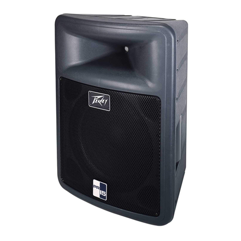
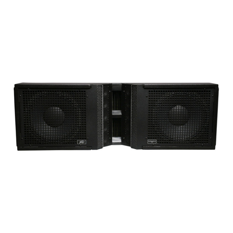
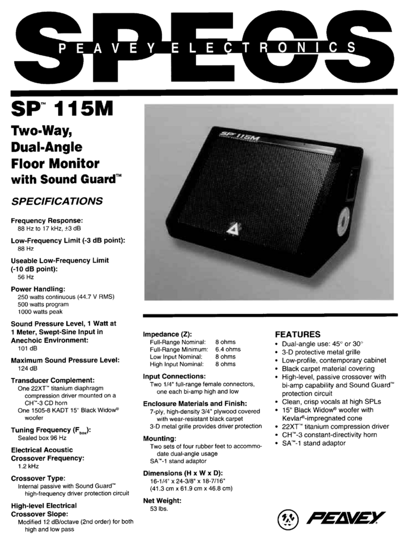
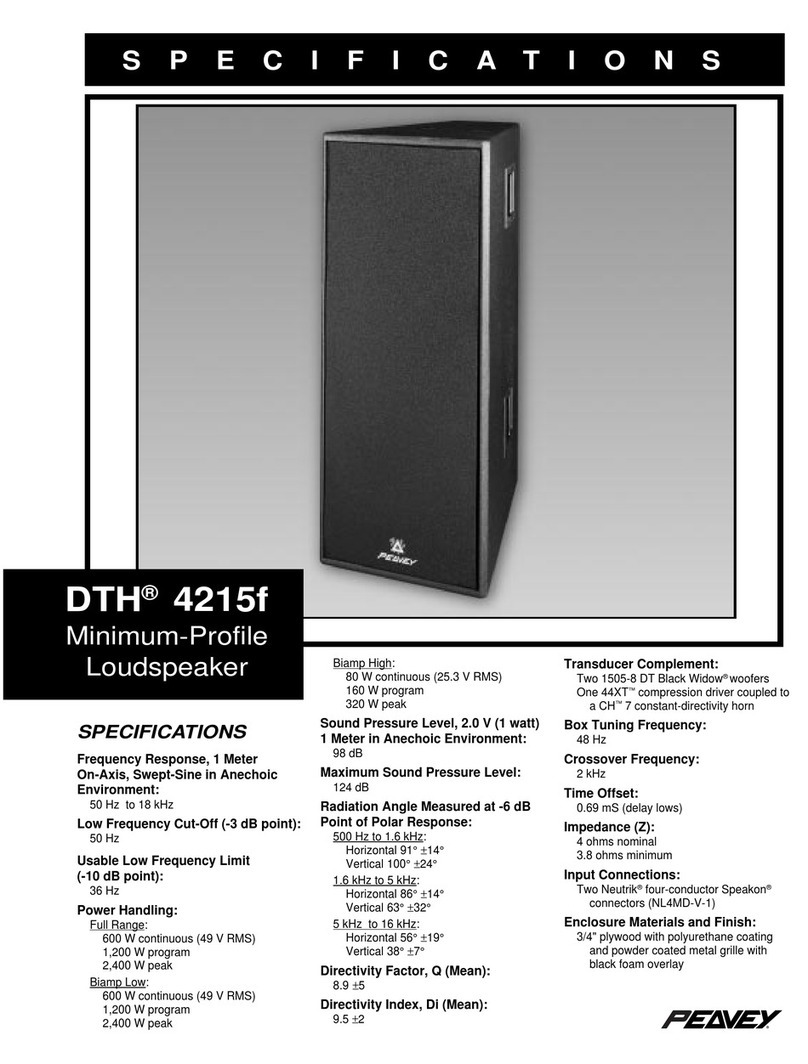
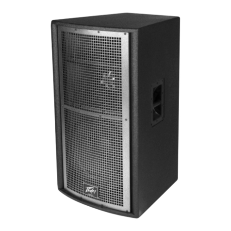
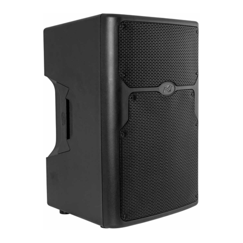
rr y [see limit tions under mounting
instructions]. Both versions of the ILS
1264 re solidly constructed of 3/4"
void free popl r plywood nd finished
with n exterior gr de h rdened bl ck
p int.
Frequency Response
This me surement is useful in
determining how ccur tely given
unit reproduces n input sign l. The
frequency response of the ILS 1264 V
is me sured t dist nce of 1-meter
using 1 w tt (into the nomin l
imped nce) swept-sine input sign l.
As shown in figure 1, the selected
drivers in the ILS 1264 V combine to
give smooth frequency response
from 63 Hz - 18.5 kHz.
Directivity
Be mwidth is derived from the -6 dB
points from the pol r plots (see Figure
3) which re me sured in whole
sp ce nechoic environment. Q nd
Directivity Index re plotted for the on-
xis me surement position. These re
specific tions th t provide reference
to the cover ge ch r cteristics of the
unit. These p r meters provide insight
for proper pl cement nd inst ll tion
in the chosen environment. The
blending of the components of the ILS
1264 V exhibit desir ble be mwidth
nd directivity (Figure 3 nd 4)
suit ble for sound reinforcement
pplic tions.
Power Handling
There re m ny different ppro ches
to power h ndling r tings. Pe vey
r tes this loudspe ker system’s power
h ndling using full-r nge form of the
AES St nd rd 2-1984. Using udio
b nd 20 Hz to 20 kHz pink noise with
pe ks of four times the RMS level,
this strenuous test sign l ssures the
user th t every portion of this system
c n withst nd tod y’s high technology
music. This r ting is contingent upon
h ving minimum of 3 dB of mplifier
he droom v il ble.
Harmonic Distortion
Second nd third h rmonic distortions
vs. frequency re plotted in Figures 5
nd 6 for two power levels. Ten
percent (10%) of r ted input power
nd either one percent (1%) of r ted
input power or one w tt, whichever is
gre ter. Distortion is re d from the
gr ph s the difference between the
fund ment l sign l (frequency
response) nd the desired h rmonic.
As n ex mple, distortion curve th t
is down 40 dB from the fund ment l
is equiv lent to 1% distortion.
Mounting
Caution: Before ttempting to
suspend this spe ker, consult
certified structur l engineer. Spe ker
c n f ll from improper suspension,
resulting in serious injury nd property
d m ge. Other enclosures m y be
suspended below one ILS 1264 V.
However, the combined weight of
ddition l enclosures nd ll c bles,
cl mps nd other h rdw re must not
exceed 330 pounds. The ILS 1264 V
weighs 70 pounds nd the m ximum
combined weight suspended from the
uppermost mounting br cket
ssemblies must not exceed 400
pounds. M ximum enclosure ngle
45o. Use only the correct m ting
h rdw re. All ssoci ted rigging is the
responsibility of others.
Architectural and Engineering
Specifications
The loudspe ker system sh ll h ve
n oper ting b ndwidth of 63 Hz -
18.5 kHz. The nomin l output level
sh ll be 96.0 dB when me sured t
dist nce of one meter with n input of
one w tt. The nomin l imped nce
sh ll be 8.0 ohms. The m ximum
continuous power h ndling sh ll be
700 w tts, m ximum progr m power
of 1,400 w tts nd pe k power input
of t le st 2,800 w tts, with
minimum mplifier he droom of 3 dB.
The nomin l r di tion geometry sh ll
be 60 degrees in the horizont l pl ne
nd 40 degrees in the vertic l pl ne.
The outside dimensions sh ll be
27.00 inches high by 19.38 inches
wide by 17.63 inches deep. The
weight sh ll be 70 pounds. The
loudspe ker system sh ll be n
Architectur l Acoustics model ILS
1264 V.
This product is m nuf ctured under
U.S. p tents 6,059,069 nd
6,064,745.
3 + 2 YEAR LIMITED
WARRANTY
NOTE: For det ils, refer to the
w rr nty st tement. Copies of
this st tement m y be obt ined
by cont cting Pe vey Electronics
Corpor tion, P.O. Box 2898, Meridi n,
Mississippi 39301-2898.
4
