Peecker Sound AS180 User manual

User’s Manual DOUBLE ARRAY series
SOUND REINFORCEMENT ACOUSTIC RESEARCHCONTROLLED RADIATION
1
DOUBLE ARRAY USER’S MANUAL

DOUBLE ARRAY seriesUser’s Manual
SOUND REINFORCEMENT ACOUSTIC RESEARCHCONTROLLED RADIATION
2
TABLE OF CONTENTS
1. PROJECT PHILOSOPHY pag. 3
2. A NEW CONCEPT OF SOUND pag. 3
3.THE PEECKER SOUND DOUBLE ARRAY pag. 4
4. A PRACTICAL EFFECT pag. 4
5. CERTIFICATIONS pag. 6
5.1 Measurements and tests on AS120 speaker
6. THE DOUBLE ARRAY SERIES INNOVATION PROCESS pag. 8
6.1 A market niche
6.2 “Music inside, silence outside”
6.3 Double Array series engineering
6.4 CAD 2D-drawing (exported in JPG)
6.5 CAD 3D-drawing (exported in JPG)
7. THE OPERATION SCHEDULE pag. 12

User’s Manual DOUBLE ARRAY series
SOUND REINFORCEMENT ACOUSTIC RESEARCHCONTROLLED RADIATION
3
����������������������������
� � �
���������������������
�
��� ������� ��� ������� ��������� ������ ��������� ��� �����������
������� ��� ������ ������� ��� ������������ ��� ������ ����� ��� ������
������������������������������������������������������������
�������������������������������������������������������������
������� ������� ������ ����� �������� ���� �������� ��� �������
����������� ���������� ����� ������ ��� ����� ������������������ ���
���������������������������������������
��� ��� ������ ����������� ������ ��� ������� ��������� ����
�������� �������� ��� ������������� ����������� ������������
���������� ��� ���������� ��� ������������ ����� ������ ����� �� ������
���������� ��������� ������� ��������� �� ������ ���������� ���
�����������������������
�
�
�������������������������������������������������������
�������� ��� ����������� ��� ������ ������ ������ ���� ������ ��� ���������
��������� ������������ �� �������� ��� ����������� ��� �������� ���������
��������������������������������
�
�
����������������������
����������� �� ���������� ������� �� ������ ���������� ������ ��������
�������������� ��� ���� ����������� ���� ����������� ������
���������������� �������� ����������� ��� ������ ��� ������������ �������
������������ ������������� ��� ������ ��� ��� ���� ��������������
����������������������������������������������������
���� ����� ���� �������� ���������� ������ ����������������� �������
If we try to channel sound to the dance floor by means of horns positioned
inside or in front of the speakers, we will only make matters worse, as the
sound quality will deteriorate unacceptably.
2. A NEW CONCEPT OF SOUND
Looking at the polar diagrams of an individual speaker at low frequency,
we will see almost omnidirectional radiation (i.e. the same radiation in all
directions). However, a considerable reduction in sound dispersion at various
angles can be achieved simply by positioning four speakers in a line.
As we increase the number of speakers, the sound emission angle will
increasingly narrow.
Note the significant effect of eight sources set in a line in the drawing below.
It should be noted, however, that the effect achieved by narrowing the sound
beam will only occur along the axis on which the speakers are positioned,
while on the perpendicular axis no change will occur by doing this as
compared to using just a single transducer.
1 . PROJECT PHILOSOPHY
The main problem with sound reinforcement systems has always been
to concentrate sound where it is actually needed and lower it perceptibly
elsewhere.
Unfortunately, sound waves, by their very nature, are a serious hindrance
to the achievement of this goal since they tend to be fairly directional
at mid and high frequencies, while at low frequencies they remain
omnidirectional. This phenomenon becomes immediately apparent
when we move around any speaker. As we move away from the axis,
we will notice a progressive lowering of the sound of voices and solo
instruments, while the sound of the keyboard and electric bass guitar will
remain unchanged.
Even if we try to concentrate sound by aiming the speakers towards the
dance floor, or by suspending them from the ceiling, low frequencies
will still produce high decibel values at a considerable distance from the
dance floor, potentially causing serious problems of compliance with the
noise pollution regulations.
DANCE FLOOR
DANCE FLOOR
DANCE FLOOR
HORN LOADING
Dwg 1. Dispersion angle differences between standard horn-loaded speakers and line arrays (4 and 8 elements)

DOUBLE ARRAY seriesUser’s Manual
SOUND REINFORCEMENT ACOUSTIC RESEARCHCONTROLLED RADIATION
4
����������������������������
� �
����������� ����� ���� ���������� ��� ��������������� ���� �������
������� ��� ��� ����� ������ ������� ��� ���� ����� ������ �����
�������������� ������� ���������� ��������������� ������ �������
���������������������������������
�
������������������������������
��������������������������������������������������������������
������������������������������������������������������������������
���������������������������������������������������
������������������������������������������������
���� ���� ��� ����� ������ ������� �� �� ��������� ���
��������� ���������� ������� ������ ������������ ������ �������
���������������������������������������������������������������
�
����������������
�������������������������������������������������������������
������������������������������������������������������������������
����������������������������
���� ���������� ���� ��� ��� ��� ������ ������� �� ���� ��� ���������
������������� ��������� ���� ��� ��� �������� ������� ������ ������ �� ��� ���
���� ���������� �������� ���� ������� �������� ������������� �������� ���
����������������������������������������������������������÷�������
�
�
�
�
�
����������������������������
� �
����������� ����� ���� ���������� ��� ��������������� ���� �������
������� ��� ��� ����� ������ ������� ��� ���� ����� ������ �����
�������������� ������� ���������� ��������������� ������ �������
���������������������������������
�
������������������������������
��������������������������������������������������������������
������������������������������������������������������������������
���������������������������������������������������
������������������������������������������������
���� ���� ��� ����� ������ ������� �� �� ��������� ���
��������� ���������� ������� ������ ������������ ������ �������
���������������������������������������������������������������
�
����������������
�������������������������������������������������������������
������������������������������������������������������������������
����������������������������
���� ���������� ���� ��� ��� ��� ������ ������� �� ���� ��� ���������
������������� ��������� ���� ��� ��� �������� ������� ������ ������ �� ��� ���
���� ���������� �������� ���� ������� �������� ������������� �������� ���
����������������������������������������������������������÷�������
�
�
�
�
�
3. THE PEECKER SOUND DOUBLE ARRAY
The Peecker Sound research engineers have designed an exclusive system
where loudspeakers are positioned on a double line, thereby reducing the
radiation along the two axes. This arrangement of transducers, called Double
Array (hence the name of the series), produces a sound beam with a strong
concentration along the axes perpendicular to the plane on which the
loudspeakers are positioned.
The invention refers to sound systems with controlled and delimited diffusion,
in which the many different sound sources, such as cone loudspeakers, are
arranged sometimes in double array formation (hence the name of the series
- Double Array), sometimes suitably spaced out from each other according
to pre-established and differentiated steps, with a level-plane, concave dome-
shaped, trunk-conical layout or according to some other configuration.
Such sources – the cone loudspeakers – are, preferably but not exclusively,
fixed to support trusses or rigging systems that can have reticular, panel or
continuous form and essentially delimit the sound reinforcement systems.
With the systems configured in this way, the cone loudspeakers are positioned
at the same distance from each other or at variable distances and in a specific
way according to the reduction of sound diffusion one is aiming to achieve
in the adjoining peripheral areas. With reference to the well-known physical
laws regarding the diffusion of sound waves in the air and the interference
phenomena occurring between the selfsame sound waves emitted by more
than one adjoining and/or combined source, it can be noted that, based on
the sources’ distance from each other, their direction and sound pressure, it is
possible to add, subtract, direct and/or alter their overall sound effect.
From these preliminary remarks, putting what can be gleaned from the
textbooks on Acoustical Physics in simple and intelligible language, we
can state that by aligning several sound sources, it is possible to alter
the dispersion angle of every sound source and achieve an overall
irradiation effect of the whole set that is narrower and more targeted
towards a desired direction.
The Double Array Series systems aim to exploit this principle in order to design
sound systems with controlled and delimited radiation with the following
requirements:
- sound sources (the cone loudspeakers) are fitted out on continuous panels or
are profiled on rigging systems or truss structures with level-plane, concave,
trunk-conical or different layouts, according to double arrays, namely several
essentially parallel line arrays;
- audio systems formed in this way can be used in wall applications for a
specifically and/or particularly oriented sound reinforcement, for overhead
or ceiling applications and for delimited sound diffusions.
Advantages achieved using sound systems with Double Array Series
loudspeakers essentially consist in obtaining:
•greatest sound intensity, available power being equal, in the area facing
the systems where sound reinforcement is asked;
•easiest intelligibility of acoustic signal in the area included in the cone/
cylinder of sound irradiation;
•extreme reduction of sound level in the zones adjoining the systems,
outside the cone of sound irradiation;
•maximum abatement of environmental noise pollution.
For instance, a 105 dB average intensity of sound emission, for standard
systems for public dance entertainment places (dance clubs, night clubs,
music pubs, etc.), corresponds to a noise value generically included
between 80 and 85 dB, in the zones surrounding the dance floor.
A peripheral sound decrease can be achieved, both around the floor
and in the surrounding zone, with a controlled and delimited diffusion
Double Array Series sound system, for example hanging from an about 3,5
m height ceiling over a dance floor, with a remaining noisiness included
between reasonably bearable 65 and 70 dB. In this way, the area of highest
acoustic power is only for dancing patrons.
4. A PRACTICAL EFFECT
Placing one Double Array speaker above a dance floor can result in
lowering the sound outside the floor from 10 to 30 dB!
This means that in a venue where the sound level with a standard system
is 105 dB on the floor and 80 dB in the perimeter outside the venue itself,
adopting a Double Array sound system can reduce the outside level to
just 60-70 dB.
Dwg 3. With Peecker Sound double array the sound beam gets thinner in both directions
Dwg 2. With a single line array (positioned on plane X) the sound beam is very narrow
in the horizontal direction, but it remains very wide in the vertical one

User’s Manual DOUBLE ARRAY series
SOUND REINFORCEMENT ACOUSTIC RESEARCHCONTROLLED RADIATION
5
Manuale DOUBLE ARRAY SERIES
Double Array Series
30m 20m 10m
0m 30m
-20dB -17dB -13dB 0dB -20dB
AREA SONORIZZATA
DIFFUSORE TRADIZIONALE
Con un diffusore tradizionale, a 10 metri dal
centro della pista
la diminuzione del livello
sonoro è di soli -13
dB e a 30 metri si mantiene
a
-
20
dB.
30m 20m 10m
0m 30m
-30dB -26dB -22dB 0dB -30dB
AREA SONORIZZATA
AS120 CROSSFIRE
Con il rivoluzionario sistema AS120 CROSSFIRE, a
10 metri dal centro della pista, la dimin
uzione del
livello sonoro è già di -22 dB e a 30 metri
raggiunge
i
-
30
dB.
-15dB
-15dB
-20dB
-25dB
-30dB
-20dB
30m 20m 10m 0m 30m
Manuale DOUBLE ARRAY SERIES
Double Array Series
30m 20m 10m
0m 30m
-20dB -17dB -13dB 0dB -20dB
AREA SONORIZZATA
DIFFUSORE TRADIZIONALE
Con un diffusore tradizionale, a 10 metri dal
centro della pista la diminuzione del livello
sonoro è di soli -13 dB e a 30 metri si mantiene
a
-
20
dB.
30m 20m 10m
0m 30m
-30dB -26dB -22dB 0dB -30dB
AREA SONORIZZATA
AS120 CROSSFIRE
Con il rivoluzionario sistema AS120 CROSSFIRE, a
10 metri dal centro della pista, la dimin
uzione del
livello sonoro è già di -22 dB e a 30 metri
raggiunge
i
-
30
dB.
-15dB
-15dB
-20dB
-25dB
-30dB
-20dB
30m 20m 10m 0m 30m
Manuale DOUBLE ARRAY SERIES
Double Array Series
30m 20m 10m
0m 30m
-20dB -17dB -13dB 0dB -20dB
AREA SONORIZZATA
DIFFUSORE TRADIZIONALE
Con un diffusore tradizionale, a 10 metri dal
centro della pista
la diminuzione del livello
sonoro è di soli -13
dB e a 30 metri si mantiene
a
-
20
dB.
30m 20m 10m
0m 30m
-30dB -26dB -22dB 0dB -30dB
AREA SONORIZZATA
AS120 CROSSFIRE
Con il rivoluzionario sistema AS120 CROSSFIRE, a
10 metri dal centro della pista, la dimin
uzione del
livello sonoro è già di -22 dB e a 30 metri
raggiunge
i
-
30
dB.
-15dB
-15dB
-20dB
-25dB
-30dB
-20dB
30m 20m 10m 0m 30m
With a standard loudspeaker system, the sound
level at 10 metres from the centre of the floor
drops by just -13 dB and at 30 metres by -20 dB.
STANDARD LOUDSPEAKER SYSTEM
SOUND COVERAGE
With the revolutionary AS120 Crossfire system,
the drop in sound level at 10 metres from the
centre of the floor is already -22 dB and at 30
metres can be as much as -30 dB.
SOUND COVERAGE

DOUBLE ARRAY seriesUser’s Manual
SOUND REINFORCEMENT ACOUSTIC RESEARCHCONTROLLED RADIATION
6
0 m 3 m 6 m 12 m 20 m 30 m
105 dB
100 dB
95 dB
90 dB
85 dB
80 dB
75 dB
0 m 3 m 6 m 12 m 20 m 30 m
105 dB
100 dB
95 dB
90 dB
85 dB
80 dB
75 dB
0 m 3 m 6 m 12 m 20 m 30 m
105 dB
100 dB
95 dB
90 dB
85 dB
80 dB
75 dB
0 m 3 m 6 m 12 m 20 m 30 m
105 dB
100 dB
95 dB
90 dB
85 dB
80 dB
75 dB
5. CERTIFICATIONS
UNIVERSITY OF PARMA - DEPARTMENT OF INDUSTRIAL ENGINEERING
Testing was conducted according to the following two different methods:
1) measurement of the polar dispersion diagrams (directivity curves) in a
simulated free field, using a turntable and the MLSSA system of analysis;
2) measurement of the sound level spectrum produced at 1.5 metres from the
ground by the AS120 speaker mounted in operating position (suspended
at 3.5 metres from the reflecting floor and pointing downwards) along two
orthogonal directrices.
The first measurement makes it possible to quantify the speaker’s directive
emission properties: such data, for example, is required when using acoustics
simulation programs for indoor venues.
The second measurement, on the other hand, enabled experiments to be
carried out to verify the speaker’s behaviour in real-life operating conditions,
taking into account, among other things, the reflection of the floor.
The outcomes of these tests clearly show the outstanding ability of the AS120
Crossfire system to control acoustic energy in a well-defined area.
STUDIO ESA - FLORENCE
Testing was performed by installing an AS120 Crossfire speaker system
and a standard system in an outdoor dancing venue. In both cases under
investigation the speakers were suspended from the ceiling, 3.5 metres
above the ground, and testing was conducted at 1.5 metres from the
ground.
The investigation showed that the AS120 Crossfire system produced a
significantly greater reduction in sound pressure levels outside the dance
floor than the standard system.
CENTRO ACUSTICO DI PROGETTAZIONE AMBIENTALE (ACOUSTIC
CENTRE OF ENVIRONMENTAL DESIGN) - REGGIO EMILIA
The numerous tests conducted in the relevant environment clearly showed
that the AS120 Crossfire system has a greater ability to concentrate sound
emission than any other standard speaker.
5. 1 Measurements and tests on AS120 speaker
THE DOUBLE ARRAY SYSTEM IS COVERED BY
INTERNATIONAL PATENT No. 01280080
The above diagrams clearly illustrate the significant reduction in sound level that can be
achieved outside the floor by using the AS120 Crossfire system
instead of a traditional speaker.
Measurements by STUDIO ESA (Florence)
STANDARD LOUDSPEAKER SYSTEM
AS120 CROSSFIRE LOUDSPEAKER SYSTEM
A) Single AS120 speaker in the middle
of the floor;
Pmax (C) = 105 dB
Pfloor edges (B) = 90 dB
Pcorners (S) = 87 dB
Pmax (C) = 105 dB
Pfloor edges (B) = 97 dB
Pcorners (S) = 93 dB
Pmax (C) = 105 dB
Pfloor edges (B) = 98 dB
Pcorners (S) = 95 dB
B) Four AS120 speakers at 4 metres;
C) Four AS120 speakers at 6 metres;
HYPOTHETICAL FLOOR 10x10m (100 mq)

User’s Manual DOUBLE ARRAY series
SOUND REINFORCEMENT ACOUSTIC RESEARCHCONTROLLED RADIATION
7
We notice that four speakers produce a much more homogeneous sound
distribution across the floor. Placing the speakers at 6 metres from each other
reduces the difference from the centre to the edge of the floor from 15 dB to
just 7 dB.
Since four AS120 speakers are too many for a 100 m2floor, the same effect can
be achieved with AS60 speakers.
A) Spectrum measurement of the sound level produced at 1.5
metres from the ground by one AS120 speaker mounted in
operating position at a height of 3.5 metres from the reflecting
floor, pointing downwards.
B) Spectrum measurement of the sound level produced at 1.5
metres from the ground by four AS120 speakers mounted in
operating position, 4 metres from each other, at a height of 3.5
metres from the reflecting floor, pointing downwards.
C) Spectrum measurement of the sound level produced at 1.5
metres from the ground by four AS120 speakers mounted in
operating position, 6 metres from each other, at a height of 3.5
metres from the reflecting floor, pointing downwards.

DOUBLE ARRAY seriesUser’s Manual
SOUND REINFORCEMENT ACOUSTIC RESEARCHCONTROLLED RADIATION
8
6. THE DOUBLE ARRAY SERIES INNOVATION PROCESS
6.1 A market niche
In early summer 1996, Peecker Sound counted more than 100 fixed
installations in Italy and abroad at different hangout spots including dance
halls, night clubs, lounges, bars, etc... In summer, these typical venues
offer visitors a thriving night-life and the possibility to dance and have
fun outdoors. So, as at the beginning of each new season these hotspots
reopened and Peecker Sound’s technicians and engineers were to provide
their usual, yearly Customer Service activities, they kept on struggling to
handle two thorny problems:
1) owners complaining about poor sound pressure levels around the dance
floor area with dissatisfaction of both the resident deejays spinning at the
club’s and of the paying visitors who were still used to the loudness of the
large audio systems installed at “indoor” winter spots;
2) steamed managers who were to handle an upset neighbourhood
relentlessly complaining about the loudness of the audio system causing
nuisance and annoyance to the people living nearby. The neighbourhood
was quite rightfully making appeal to the Italian Piece of Legisltion No. 477
on acoustic pollution (and the following enforcement acts) implemented in
October 1995 to control the maximum noise emission levels by establishing
mandatory values that were very restrictive for those playing music
efficiently.
This scenario had come to a critical level when the managers decided to
take the following compromise solutions to lessen the problems:
1. Installing short-throw, traditional, “forward firing” loudspeaker systems
that are with their axis parallel to the floor (see Fig. 1); this arrangement,
however, involved some inevitable phase shifts due to the different
acoustic paths of the sound reproduced by the loudspeakers, especially
in the mid-high range;
2. Giving up subwoofers for the reproduction of low-pitched audio
frequencies to deejays’ great disappointment;
3. After long consultancy studies, implementing acoustic barriers out of
insulating and sound absorbing material (i.e. Celenit, Eraclit, Calibell) to the
owners’ malcontent due to the high workmanship costs;
4. Setting up adequate loudspeaker system suspending/rigging structures
in highly soundabsorbing electro-acoustic materials (as for instance
reinforced concrete) to the dissatisfaction of the architects who felt these
structures were detrimental to the typical summer vocation of the clubs.
This is why our Top Management decided that a deep change was
required and a unique, fully innovative system had to be worked out in
order to clear all foregoing problems. Eventually, the solution came and
consisted of a controlled radiation system conceived to concentrate the
sound pattern within an extremely limited and restricted space.
By so doing, the Company Management aimed at designing a product
with a triple target:
- Number one: getting finally rid of all afore said conflicts and meet
with the expectations of a large number of peecker sound customers
(as numerous “summer hotspots” managers were also owners of
“traditional” indoor dancing rooms);
- Number two: accurately complying with the applicable, yet very strict
standards on acoustic pollution;
- Number three: hopefully acquiring a market share associated with the
new generation trend of dine&dance restaurants, hotels with an own
night club up to those cruising boats whose entertainment hall was
close to the cabins (although the latter was not in the original picture!).
We will read later how all three targets were reached and a product
(AS120 Crossfire) was developed and later contributed to consolidate
Peecker Sound ranking among the leading manufacturers in the field of
sound entertainment.
6.2 “Music inside, silence outside”
The final aim of this Peecker Sound project was to bring forth an audio
system with highly dynamical levels on the dance floor, medium levels
in the adjacent surrounding area and low Laeq (i.e. equivalent A-weighted
sound pressure level) on the club walls. While initially these systems
prevalently came into question for outdoor spots, they are presently
increasingly required also for indoor places in order to provide compliance
with most recent regulations enforcing very strict sound level limitations.
Everywhere in the world, all loudspeakers are constructed to provide a
fairly good sound directivity in the mid and high range frequencies (voices
and solo instruments), but nearly no directivity at all in the low frequency
range (from 20 through 500 Hz). Low sound frequencies radiate in any
direction without any apparently possible control. If you stand behind a
subwoofer, you would still hear the same basses at the same distance in
front. For this reason, the traditional sound systems for dance halls feature
a really small difference between sound levels on and off the dance floor
thus obliging the inspectors to decrease the volume. The longterm effects
of this intervention can turn to a real disaster with people no longer visiting
dancing clubs, because they miss the physical sound pleasure and discos
being deserted because of abiding the rules!
How the sound can be DIRECTED?
The only, very old method for controlling sound waves radiation is – as
usual – to design a sound guide of adequate size in front of the audio driver.
While all the experts know about acoustic horns, the concept of “adequate”
size makes it a bit more buzzing. In fact, if a good performance is achieved
at 1500 Hz with a 13 cm long horn with a 48 cm mouth, a similar device
performing at even 150 Hz only will be 10 times bigger than that!
Figure 2 above shows a dance floor with horn-loaded loudspeakers.
Figure 1. Layout scheme of forward firing loudspeakers
Figure 2. Layout of a traditional loudspeaker arrangement

User’s Manual DOUBLE ARRAY series
SOUND REINFORCEMENT ACOUSTIC RESEARCHCONTROLLED RADIATION
9
As one can see, the only way to send sound to the floor is to adjust the
horn devices by a suitable radiation angle “α” between normal at ground
and the loudspeaker centre of gravity. It may be hard to believe, but this
was the only method used to direct low sound frequencies to the dance
floor until short ago.
What about today? We presently offer Double Array Series (AS6 -
AS60 - AS120 - AS180): after many years of specifically focused research,
these loudspeakers have been tested on tens of different outdoors and
indoors installations in all European countries and actually brought forth
a revolution of the very sound texture concepts.
They provide a real absolute innovation in the field of acoustics because
they completely turn around the whole classical thinking of traditional
technicians.
The new concept consists of a double array of throughout same loud
speakers designed to shift the phase off the axis so to provoke at least
10 dB damping of sound variations in foreign areas while maintaining an
unaltered sound volume and feeling on the dance floor.
6
sperimentati in decine di diversi impianti all'aperto e al chiuso, brevettati in tutti i
paesi della comunità europea, questi particolari diffusori hanno rivoluzionato i
principi stessi della sonorizzazione.
Essi costituiscono un'autentica innovazione assoluta per il mondo
dell'acustica, poiché sconvolgono i classici parametri di riferimento su cui si
basa il modo stesso di ragionare dei tecnici tradizionali.
Il principio è quello di un doppio array di altoparlanti uguali, capaci di creare
sfasamenti fuori asse, tali da attenuare di almeno 10 dB la variazione sonora
nelle aree non interessate, mantenendo inalterati i suoni e le sensazioni in
pista.
Fig. 3 La serie Double Array
6.3 Double Array Series engineering
The company’s Management, having accurately detailed the requirements
of this market niche, called a project-meeting to launch the engineering
of an innovative system suitable to orient and concentrate sound
radiation to the dancing floor, without causing any annoyance outside
and keeping well within the strict limitations established by the applicable
law provisions (as already explained above).
At that time, the company’s Top Management grasped at once that such
a hard engineering and design process could never be carried out and
successfully completed by sticking to the traditional design concepts that
had been applied so far. This prompted the company to involve in the
project a variety of different parties from inside and outside the company
to collaborate and give their contribution at all main steps of the design
process from the early definition of the product specifications.
After exchanging views with the Engineering Department, the company’s
Management decided that for the first time in its life, Peecker Sound would
have led and supported the design, the engineering and the production
of a new system by a project-wise approach instead of assigning the design
and production tooling tasks to the Engineering Department as it always
happened before. All parties who normally acted in production cycles
needed to be involved and collaborate (including company’s functions that
would normally not interact with a product design project, raw material and
component suppliers up to final customers).
The die was cast: the corporate Top Management took immediate action
at company’s internal levels by means of direct, informal contacts and a
staff motivation action aimed at raising awareness for the new product. On
company’s external levels, the Management set off to drag in the project
team some outstanding actors selected among the most representative
and influent suppliers and customers.
So the Company’s Management immediately set about shortly defining all
organization and logistic details:
1) It was resolved that the new sound texture project had to have its own
venue and for this reason a 250 sqm area was made available at the premises
in Reggio Emilia where all project-dedicated equipment would be installed
and where the prototypes would be assembled and tested;
2) Responsible staff members out of all corporate functions were selected
and assigned to project execution, while G. Gandolfi (R&D Division) was
appointed as project leader with the task of supervising the works and
informing the Management about the progress of the project by means of
periodical meetings;
3) It was established that all corporate functions, whose part of staff was
assigned to the new project, would rearrange themselves so that they would
not longer need to distract the transferred people from the mission of the
new project (which was possible thanks to the proximity of the locations);
4) Contacts were taken with the most representative suppliers and customers
in order to “recruit” them into the project: suppliers promptly turned out
quite ready to collaborate with the new system design (some of them had
even already considered similar projects within their companies). Attracting
and sensibilizing customers was indeed a more difficult task and one can
really say that this particular mission succeeded just because of the nearly
intimate management relationship with the most “important” customers;
5) A maximum project deadline (12 months) was established;
6) After a consultation with the financial managers and diverse meetings
with field operators (banks and investment companies), a maximum
project budget (1.5 billion “old” Lira) was allocated in compliance with the
company’s resources.
In summary, the project team was made up of:
• the entire corporate Engineering Department;
• all staff of corporate R&D Department;
• three members out of the corporate Sales Division;
• two internal Production members;
• one engineer and two technicians of the corporate Electronics Department;
• two of the best people in the internal Carpentry Department;
• one person from each Supplier of: a) raw materials, b) components (horns,
loudspeakers,..), c) grids and suspension systems
• two members of the corporate Management of two of the most prestigious
clubs already equipped with a peecker sound audio system.
Moreover, the President of the Sound Corporation group, Mr. Gianni Toschi,
took personally part to the first project workshops attended by internal and
external participants listed below.
Figure 3. The Double Array series
Corporate Management
System Design
R&D Department
Engineering
Department
Suppliers
Sales Area
Representative
Customers Carpentry
Department
Production
Department
Electronics
Department
Product
Specications

DOUBLE ARRAY seriesUser’s Manual
SOUND REINFORCEMENT ACOUSTIC RESEARCHCONTROLLED RADIATION
10
Here below is a brief description of the design steps and the contributions of
the various parties involved in the project:
• After the first meetings, it was decided to “release” the customers, because
they already extensively outlined the problem in terms of relationships both
with the neighbourhood and with the inspectors (USL agencies) checking
on noise emissions. Moreover they all eagerly, already accepted to host and
install a zero series of the new product;
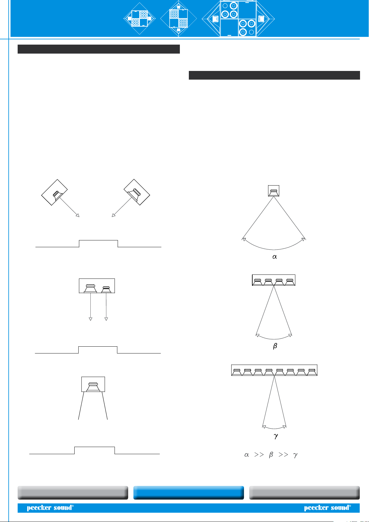
• Of course the R&D Department extensively joined the Engineering
Department throughout the entire design project and its contribution
turned out very conclusive in the selection of the raw materials and above
all in the implementation of controlled-radiation, double-array sound
reinforcement system (an absolute innovation at that time, as the actual
state-of-art in the reference field only accounted for single arrays!);
• On the contrary, the contribution of the suppliers continued over a longer
period of time and led to the following conclusions.
For indoor loudspeakers (by CIARE S.r.l.): standard components out of the
actual catalogue would have been used.
For tweeter horns (by B&C SPEAKERS S.p.A.): bespoke parts and components
would have been designed for the new product by means of a special
dedicated injection and stamping line.
For protection grids (by NUOVA LAMM): new custom-made grids would
have been designed in accordance with CAD drawings of the new product.
For the packaging (by TITAN): the project management approved an
inhouse make due to the expensive price offered by the supplier.
• A very crucial task was performed by the carpenters in terms of scraps
management and selection of the original raw material: marine plywood
(a renown, very light and waterproof material largely used in the navy field)
was selected and it was decided that the size of the speaker central element
(see below) was to be exactly the same as one half of the original raw panel
size (so to avoid any complicated and costly nesting of the wood shapes!);
• The staff from the Electronics Department was immediately asked by the
project team to develop a dedicated electronic controller for the new-born
speaker.
As a matter of fact, it became progressively clear since the very first work
hours that it would have been impossible to accurately reproduce the entire
music range (from 30 to 18,000 Hz) for every possible volume level.
The plan was to design a totally new active crossover that eventually turned
out to be our DP 60-120;
12
◊l’apporto degli operatori della falegnameria fu decisivo per quanto
riguarda la gestione degli sfridi e per la scelta del materiale grezzo di partenza:
si decise di utilizzare del multistrato marino (noto per le sue doti di leggerezza e
impermeabilità, viene spesso impiegato nelle imbarcazioni) e si stabilì, inoltre,
che la dimensione dell’elemento centrale del diffusore (vedi dopo) sarebbe
stata pari esattamente alla metà del pannello iniziale di materiale grezzo
(evitando così un elaborato e costoso processo di nesting delle sagome di
legno!);
◊lo staff proveniente dalla Divisione Elettronica venne subito chiamato in
causa dai membri del team di progetto perché si sentiva l’esigenza di realizzare
un controller elettronico dedicato al diffusore nascente.
Infatti, fin dalle prime ore di lavoro sul progetto, si era andata delineando
l’impossibilità di riprodurre fedelmente tutta la gamma musicale (da 30 a 18000
Hz) per ogni possibile livello di volume.
Si sarebbe progettato ex novo un crossover attivo: il futuro DP 60/120;
Fig. 4 Il processore DP 60/120
• The production technicians, instructed by the Engineering Department,
decided that a dedicated line would be installed at the premises in Reggio
Emilia where the new product would be assembled.
It was decided that no additional production machineries would be
required, except for electric parts and fabrication tools as for instance
drills, screwdrivers, etc… The same production technicians agreed with
the carpenters on the correct position of holes on the speaker in order to
rapidly achieve an ergonomic placement of electric cables;
• Finally, the sales manager from the Sales Area extensively
cooperated with the Design Engineers to provide the lowest
possible fabrication costs and to outline an attractive speaker look.
In the framework of this collaboration, it was decided that the
speaker was to be equipped with some strobe lights in the corner
elements without active music components (this was the only
suggestion accepted by the project staff among several ones made
by the marketing experts!).
13
◊i tecnologi di produzione, su suggerimento della Divisione Progettazione,
decisero che l’impianto di Reggio Emilia avrebbe ospitato una linea dedicata
per l’assemblaggio del nuovo prodotto.
Si decise, inoltre, che non sarebbe stato necessario un aumento dei macchinari
di produzione, se non in termini di minuteria elettrica ed utensileria di
fabbricazione come trapani, avvitatori, etc… Gli stessi tecnologi di produzione si
accordarono con gli operatori della falegnameria per un corretto
posizionamento dei fori del diffusore al fine di ottenere un rapido ed ergonomico
posizionamento dei cavi elettrici;
◊infine, i sales manager dell’Area Commerciale si prodigarono con gli
ingegneri della Progettazione per contenere il più possibile i costi della
fabbricazione e per tracciare le linee estetiche del diffusore: proprio grazie a
questa partecipazione si decise che il diffusore sarebbe stato provvisto, negli
elementi angolari sprovvisti di componenti musicalmente attivi, di alcune luci
stroboscopiche (fu l’unica proposta che venne approvata dallo staff di progetto,
fra le tantissime formulate dagli esperti di marketing!).
Fig. 5 Schizzo del diffusore nascente
At the end of the design process (that lasted approximately 6 months and
therefore 6 months well ahead of the expected deadline!) the following
specifications had been outlined:
To great satisfaction of the Corporate Management, the first prototype
was ready one month only after defining of the technical specifications
and it proved quite positive although the following modifications were
decided:
1 Using shorter PVC tubing for playing bass chords;
2 Changing the corners of the tetrahedral elements;
3 Redefining the cutting frequencies of the passive crossover.
After saving the modifications in the product folder, the required
production tooling was implemented, the final details were defined and
the part list was laid out including all outsourced parts.
The first zero series was released after production tooling (8 months after
project start-up!) and was installed in a famous club in the district
of Modena. The zero-series obtained immediate customers’ favour.
However, it was decided to hold-on with final production as the Corporate
Management first wanted to apply and obtain both Quality Certification
and Patent (finally awarded only 15 months after application) in order
to prevent copies or reverse engineering problems (which nevertheless
occurred after the large scale success of the Double Array speakers!).
Figure 4. DP 60/120 processor
Figure 5. Sketch of the new speaker
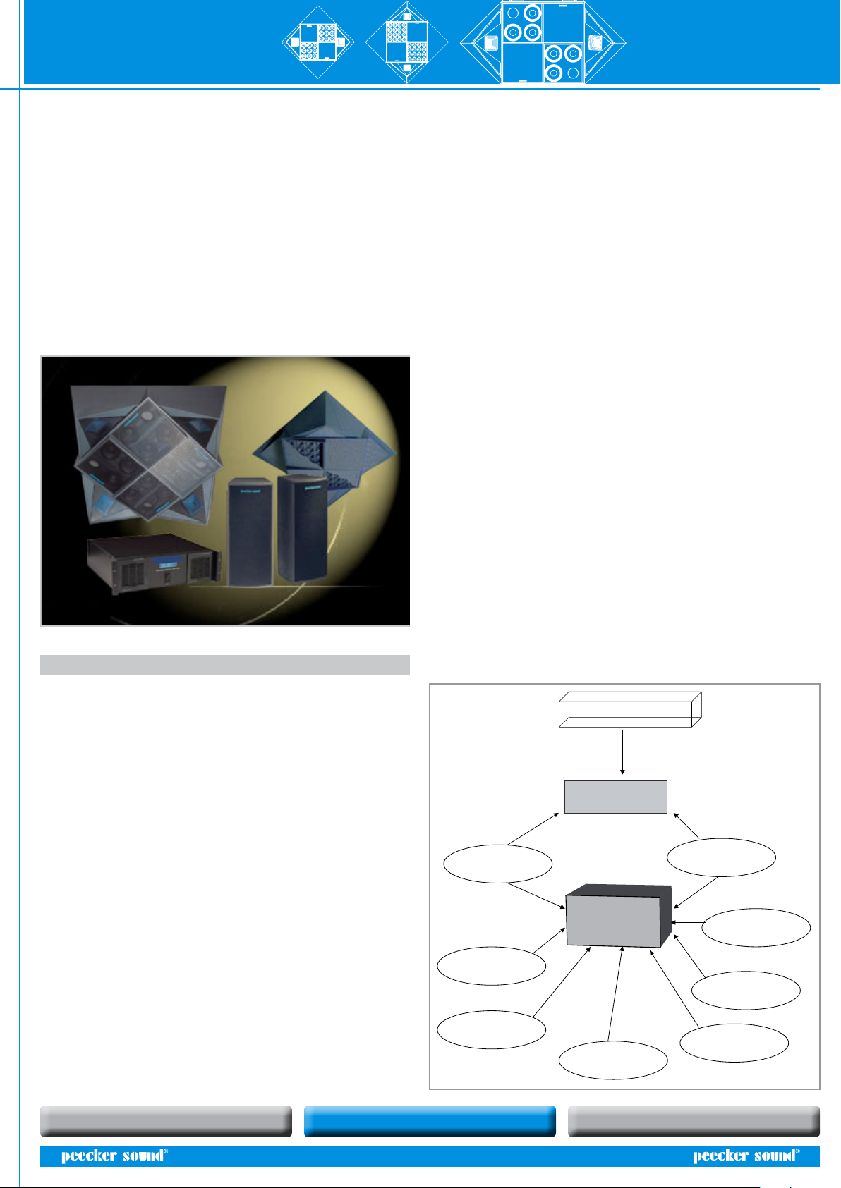
Project team Decisions made Specs/Processes
Engineering Dept.
Management of the
project team
System design
R & D Raw material
and array system
/
Production Dept. Dedicated series Series tooling
Electronics Dedicated controller Totally new design
Carpentry
Chassis - 125x125 cm
No tooling
Grids supplier
Dedicated grids
Design from CAD
drawings
Components supplier
Catalogue components
/
Enclosure supplier
Too expensive packaging
“Make” decision
Marketing
Product look and lights Lights addition
Customers
Availability of the
zero-series
/

User’s Manual DOUBLE ARRAY series
SOUND REINFORCEMENT ACOUSTIC RESEARCHCONTROLLED RADIATION
11
Central element
with the speakers Tetrahedral
element with
the lights
Prism for tweeter
accommodation
Ceiling or
suspension
structure
Further collaboration with the University of Parma provided measurement
of the polar dispersion diagrams and plotting of the speaker directivity
curves. In course of an additional collaboration with Studio di Ingegneria
ESA in Florence, measurement of the sound level was performed at 3.5 m
above floor on various installation types with one or more AS120 speakers
for different sizes of an assumed dance floor area (please see par. 5).
As a conclusion, after only 15 months from starting of the operations, the
project staff had come to the final configuration of the speaker, obtained
an international patent (No. 01280080, registered at EPO, European Patent
Office) and launched a mass production of what would have later been
one of the biggest Peecker Sound successes with the sale and installation of
over 2,000 systems in the following five years.
Upon final validation of the production, after confirming the modifications
applied to the zero series, the decision was taken to manufacture the AS120
loudspeaker system with the following final configuration:
- One quadrangular central element accommodating 64 5”-cone loudspeakers
for low frequencies reproduction;
- Two prism elements accommodating the tweeters for mid-high frequencies;
- Two tetrahedral elements accommodating, on request, eventual strobe
lights to improve the overall look.
Figure 6. AS120 Crossfire acoustic loudspeaker system

DOUBLE ARRAY seriesUser’s Manual
SOUND REINFORCEMENT ACOUSTIC RESEARCHCONTROLLED RADIATION
12
19
4. Disegno CAD 2D (esportazione in JPG senza i tool del CAD)
5. Disegno CAD 3D (esportazione in JPG senza i tool del CAD)
19
4. Disegno CAD 2D (esportazione in JPG senza i tool del CAD)
5. Disegno CAD 3D (esportazione in JPG senza i tool del CAD)
6.4 CAD 2D–drawing (exported in JPG)
6.5 CAD 3D-drawing (exported in JPG)

User’s Manual DOUBLE ARRAY series
SOUND REINFORCEMENT ACOUSTIC RESEARCHCONTROLLED RADIATION
13
7. THE OPERATION SCHEDULE
Panel shearing of
row material PVC pipe shearing
Front of the cabinet
drilling Inside ‘cross’
riveting
Drilling and boring
of the side element
Pipe insertion
Bottom gluing
and riveting
Installation support
fastening
Insertion of inside
reinforcing frames
Drilling of ‘cross’
and cabinet’s bottom
for wiring
Front of the cabinet
gluing and riveting
Insertion of ‘pins’ Manufacturing of
‘cabinet corners’
Manufacturing of
grille frame
Honing/Puttying
VARNISHING
(to the next page)
CARPENTRY
Inside “cross”
riveting

DOUBLE ARRAY seriesUser’s Manual
SOUND REINFORCEMENT ACOUSTIC RESEARCHCONTROLLED RADIATION
14
18
ASSEMBLY
Arrangement of the electric
components
Arrangement of signal
cables and speakON
Passive crossover
manufacturing
Wadding insertion
Speaker electric wiring
Insertion of cone
loudspeakers
Fastening of grille frame
Protective grille and brand
fastening
Compressed air cleaning
Stroboscopic light insertion Assembly of corner elements
TESTING
QUALITY CONTROL
PACKING
SHIPMENT
This manual suits for next models
3
Table of contents
Other Peecker Sound Speakers System manuals