SOUND REINFORCEMENT CONTROLLED RADIATION ACOUSTIC RESEARCHCONTROLLED RADIATION
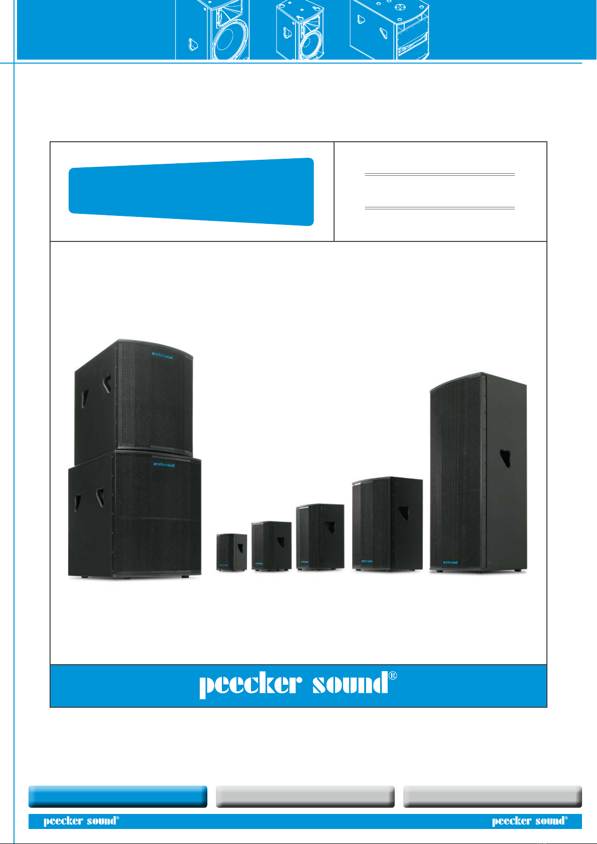
User’s Manual FORTY series
5
6. SYSTEM INSTALLATION
6.1 Floor stacked or suspended installation?
There are some arguments in favour of oor-standing installation and
some in favour of suspended installation, depending on the situation
in hand. Without taking into account possible logistical or visual issues,
which have to be assessed individually, the positive aspects of floor
stacking are mainly associated with stronger overall coupling of low
frequencies with the oor, which boosts eciency at the lower end of
the sound spectrum and increases the eectiveness and speed of the
response to low transients. This is partly because, in the case of oor-
stacking, the speaker cabinets are generally more physically constrained
than in suspended systems and are consequently more stable and rmly
anchored to the ground, which prevents part of the acoustic energy
from being transformed into structural motion and eectively being lost.
Another point in favour of oor stacking is the fact that, from a“spatial”and
“psycho-acoustic” perspective, the sound physically comes from points
close to the stage and thus close to the music scene.
Figure 7. Stack installation of Forty speakers
The choice of suspended speakers (flying system), on the other hand, is
obligatory in all cases where oor stacking fails to provide the required
sound coverage. When the mid-high frequency transducers are not high
enough above the listeners’ heads, high frequencies will be poor even at
short distances due to both the “friction”of sound on the audience (since
it is a sound absorption factor) and sound refraction phenomena caused
by the vertical temperature gradient created by the audience itself.
Therefore, oor installation is not generally very suitable for covering
substantial distances (the problem is reduced when the audience is
arranged on a sloping plane and the level of the listeners furthest away
is considerably higher than those in the front rows). Moreover, for long
distance coverage, providing sucient SPL (Sound Pressure Level) to the
rows at the back may result in excessive SPL on the front rows. In this
case, ying installation is to be preferred since, reducing the dierence in
distance from the system of close and long range listeners, it will reduce
the SPL gap and spread the sound more evenly.
6.2 Positioning angles
When installing more than one Forty Series speaker at the sides of the
stage, particular care must be taken to position them at the correct angles.
The high frequencies delivered by the horns of each speaker can in fact
cause negative interferences with those of the others at certain points or
in particular spatial directions. One way of containing this phenomenon
is to tilt the speakers in relation to each other by specic angles related
to the dispersion angle of the sound beam delivered by their individual
horns - this is correct for both vertical and horizontal tilting.
One specic technique is to tilt the two speakers by an angle close to, or not
excessively lower than, the horn’s dispersion half-angle. In this way, by shifting
slightly away from the axis of the system made up of the two coupled speakers,
the contribution of one of the two will become negligible compared to that of
the other, thereby avoiding any harmful interferences. Conversely, a narrower
dispersion angle can be achieved by bringing the long sides of the speakers
closer together, resulting in a narrower coverage and a longer throw, but with
a less even spread at close range.
The choice will therefore be guided by the shape and size of the area requiring
sound coverage.
7. PASSIVE LOUDSPEAKER SYSTEMS
The Forty Series comes in both passive and amplied versions.
The passive loudspeaker systems have particularly selective crossover lters
to achieve the most natural timbre quality at mid frequencies, which are
important for the intelligibility of speech and vocals and to deliver the clearest
possible sound and music. This is particularly useful since it makes it possible
to obtain top quality sound from the 4008, 4010MH, 4012MH, 4015MH, and
4030MH speakers without the need for an external processor: all plug and go!
The use of a processor is clearly essential for the active crossover function in
cases of multi-amplication, e.g. with all the complete subwoofer systems.
In the latter case, the delay function will allow the correct sound alignment
between the subwoofers and the upper modules. The processor is useful in
all cases requiring not only top quality sound but also speaker protection
whilst taking full advantage of its maximum output, which is a key concern in
professional sound installation. It is important, in fact, to control the amplier
input voltage so as not to damage the speaker passive components with
signals that are too powerful or otherwise unsuitable for acoustic transducers.
The following paragraph explains how and why this is the case.
Upstream, i.e. acting on the amplier’s input audio signal, it is clearly not
possible to protect the speakers from harmful phenomena originating from
the amplier itself. If an amplier malfunction generates constant or extremely
low frequency voltage (DC), this will damage the transducers regardless of the
input signal. Similarly, high voltage peaks due to switching on and o devices
upstream from the ampliers when the ampliers are operating can also
damage the transducers. Therefore, to power an electro-acoustic system, it is
important to switch on the ampliers only after the power supply to the mixer and
control electronics has been turned on and has stabilized. To turn o the system,
the reverse sequence applies, so the power amplier should be switched o rst.
We strongly recommend control and maintenance of the sound system and
strict adherence to the correct power on/o sequence of the devices making
up the audio chain.
7.1 Amplication and limitation
Generally speaking, excessive power can easily damage transducer coils due
to the overheating it causes (high RMS values for long periods of time), while
in rare cases it can damage the mechanical parts of the cone (membrane or
suspensions). In this specic case, frequencies lower than the reex tuning
frequency can cause excessive excursions (that are also pointless since the
eciency value of these frequencies is virtually nil) and consequent damage.
It is therefore advisable to always use external processors which, with the
due frequency cuts and limitations, will protect the woofer and optimize its
eciency.
The signal sent to the high frequency drivers of the Forty Series, however, is
passively protected by a special lament device. It is the user’s responsibility
not to supply a passive speaker with signals that are damaging to the
transducers. To control these signals, Peecker Sound recommends using the
PS266 processor. Using the appropriate selection of ampliers and limiters
allows speakers to achieve maximum performance without the risk of damage.
For maximum performance – i.e. exploiting transducers to the full in relation
to signal peaks – a good practical rule is to have a double-powered (“oversized”,
as we call it) amplication channel as compared with the transducer’s RMS power
tolerance. To protect the transducer coil, moreover, a limiter also needs to be
used to avoid exceeding RMS power levels for prolonged periods of time. This
is the function performed by the limiters in the Forty Series amplied models
and in the PS266 external processors.
4015MH/A 4015MH/A
40SW18/A 40SW18/A