Pegasus VIACLIN User manual

SERVICE MANUAL
LFT5508
Issue 3
VIACLIN
Alternating Pressure Mattress Overlay
Model 2502

LFT5508 - AMENDMENT RECORD
REVISION
CHANGE
NOTE
TECH.
NOTE BRIEF DETAILS SIGNATURE DATE
1
2
3025/02 011/02 To have a common flow restrictor assembly for 2503 &
5202 K.Wilson 3/9/02
023/02 -Replace part number MEC483 with MEC14753 K.Wilson 16/9/02
- - Redrawn instruction diagrams to show overlay straps
around mattress. K.Wilson 3/10/02
- - Reformated Viaclin service manual 2502 so that it is
similar in structure as the newer manuals. Changed text
‘5.5 ltr/min’ to ‘6.5 ltr/min’. Added note”EXISTING 2501
OR 2502 THAT REQUIRE A REPLACEMENT
POWERUNIT WILL BE REPLACED BY A 2503 POWER
UNIT (SA242) AND AN APPROPRIATE ADAPTER (REF:
MOD KIT MOD14831)”. See IU 088/02
K.Wilson 22/10/02
POLICY STATEMENT
Pegasus Ltd has a policy of continuous product improvement and reserves the right to change details presented in this
Service Manual without notice.
Tel: +44 (0) 23 9278 4200
Fax:: +44 (0) 23 9278 4250
E-mail: [email protected]
Web Site: www.pegasus-uk.com

LTF5508 iIssue 3
VIACLIN MODEL 2502 Oct 02
LIST OF CONTENTS
Section Title
1. SAFETY STATEMENT
2. INTRODUCTION
General
System Description
3. SETTING UP/OPERATION
Setting Up
Profiling and Knee-Breaking
Moving the Bed and Power Cuts
CPR (Cardio Pulmonary Resuscitation)
Deflation, Removal, Carrying and Storage
Alarms and Fault Finding
4. CONSTRUCTION OF PRODUCT
Major Elements of the System
Mattress
Power Unit
Technical Details
5. INFECTION CONTROL AND CLEANING
Infection Control
Cleaning Guidelines
6. EQUIPMENT MAINTENANCE
General
Power Unit
Mattress
7. TEST EQUIPMENT
8. PARTS LIST
Power Unit
Mattress

LFT5508 1.1 Issue 3
VIACLIN MODEL 2502 Oct 02
SECTION 1 - SAFETY STATEMENT
1.1. The VIACLIN system must be used in accordance with the manufacturer's instructions.
1.2. The mains electricity supply within the building where the VIACLIN system is to be used must comply
with IEE Regulations.
1.3. Only personnel trained or formally approved by Pegasus Ltd in operation and maintenance of Pegasus
systems may perform maintenance, modification or repair work on Pegasus Ltd Power Control Units.
1.4. Unqualified personnel attempting to work on Pegasus Ltd Power Control Units risk serious injury to
themselves and others, and possibly death by electrocution.
Do not work, or attempt to work on Pegasus Power Units unless you are properly qualified
to do so.
1.5. Pegasus Ltd systems are designed to comply with all relevant electrical safety, manufacturing and
performance standards published by IS0, IEE & BSI.
1.6 Materials used for cleaning procedures may be subject to COSHH regulations - manufacturer's
Instructions for Use must be followed at all times.
1.7 Materials used for maintenance and repair may be subject to COSHH regulations - manufacturer's
Instructions for Use must be followed at all times.

LFT5508 2.1 Issue 3
VIACLIN MODEL 2502 Oct 02
SECTION 2 - INTRODUCTION
2.1 GENERAL
The VIACLIN Alternating Pressure Mattress Overlay is designed for use whenever patients have some mobility problems
and/or who are vulnerable to pressure ulcer development and/or who have existing tissue damage. It gives gentle, dynamic
support to bedridden and immobile people in recumbent, supine and knee-break postures, providing alternatively support
then pressure relief to each part of the underside of the patient.
The bed can be repositioned whilst the Mattress Overlay is still inflated.
The system is suitable for use in hospitals, nursing homes and in the community.
2.2 SYSTEM DESCRIPTION
The system consists of a power unit and a mattress overlay. Audio and visual alarms activate if a fault condition exists for
more than three minutes (compressor failure, overlay or airpipe failure). An audio alarm sounds if the mains supply fails
(disconnected or switched off). These alarms alerts medical staff to the malfunction.
The specially constructed overlay comprises a series of pairs of transverse cells, which are inflated and deflated alternately.
Air to inflate the overlay is provided by an electronically controlled power unit. The air pressure in the overlay is
continuously monitored, and the system is completely self-regulating. The overlay is connected to the power unit by
means of an airpipe which features quick release connections at the power unit end, for convenience and rapid deflation,
to allow cardiac resuscitation procedures. Operator controls are purposely kept to a minimum.
The overlay is positioned on top of the normal bed mattress.

LFT5508 3.1Issue 3
VIACLIN MODEL 2502 Oct 02
SECTION 3 - SETTING UP/OPERATION
3.1 SETTING UP
CAUTION: Use only on top of the existing bed mattress.
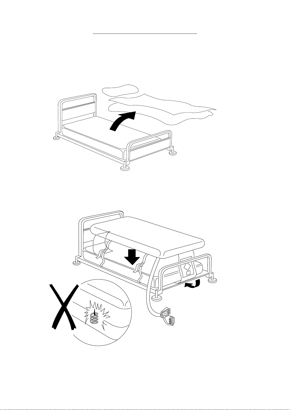
Remove the bedding from the bed.
Ensure there are no sharp objects to damage the Overlay. Place the Overlay on top of the bed mattress with the
umbilical at the foot end of the bed. Tuck the two end flaps under the bed mattress.
Secure the Overlay straps to the mattress. Do not secure to the bed frame (only secure Overlay straps loosely to the
moving parts of the bed frame, (if applicable).

LFT5508 3.2Issue 3
VIACLIN MODEL 2502 Oct 02
Hang the power unit on the bed or place on the floor.
Connect the three airpipe connectors on to the power unit connectors. Plug the power unit into a suitable mains
socket and switch on.
The system will take approximately 20 minutes to reach full inflation pressure, at which time the green NORMAL light
will come on and the amber light will extinguish. During this start up phase the red FAULT light may come on and the
audible alarm sound, if this occurs turn the power unit off and back on again to reset the alarm.

LFT5508 3.3Issue 3
VIACLIN MODEL 2502 Oct 02
Once inflated, check the securing straps and tighten if required. For maximum benefit, use only one sheet loosely
placed over the mattress. If the sheet is tucked in ensure that it is left loose over the mattress to avoid hammocking.
Once a patient is placed on the mattress the system will adjust automatically to the patient characteristics
(weight/position) to provide optimum clinical benefit for each patient. The mattress may feel firm at first until it has
adjusted to the individual. Allow approximately 15 minutes for this automatic adjustment to be completed.
If the mattress does not perform as described above, please refer to Section F of this guide ‘Alarms and Fault Finding’.
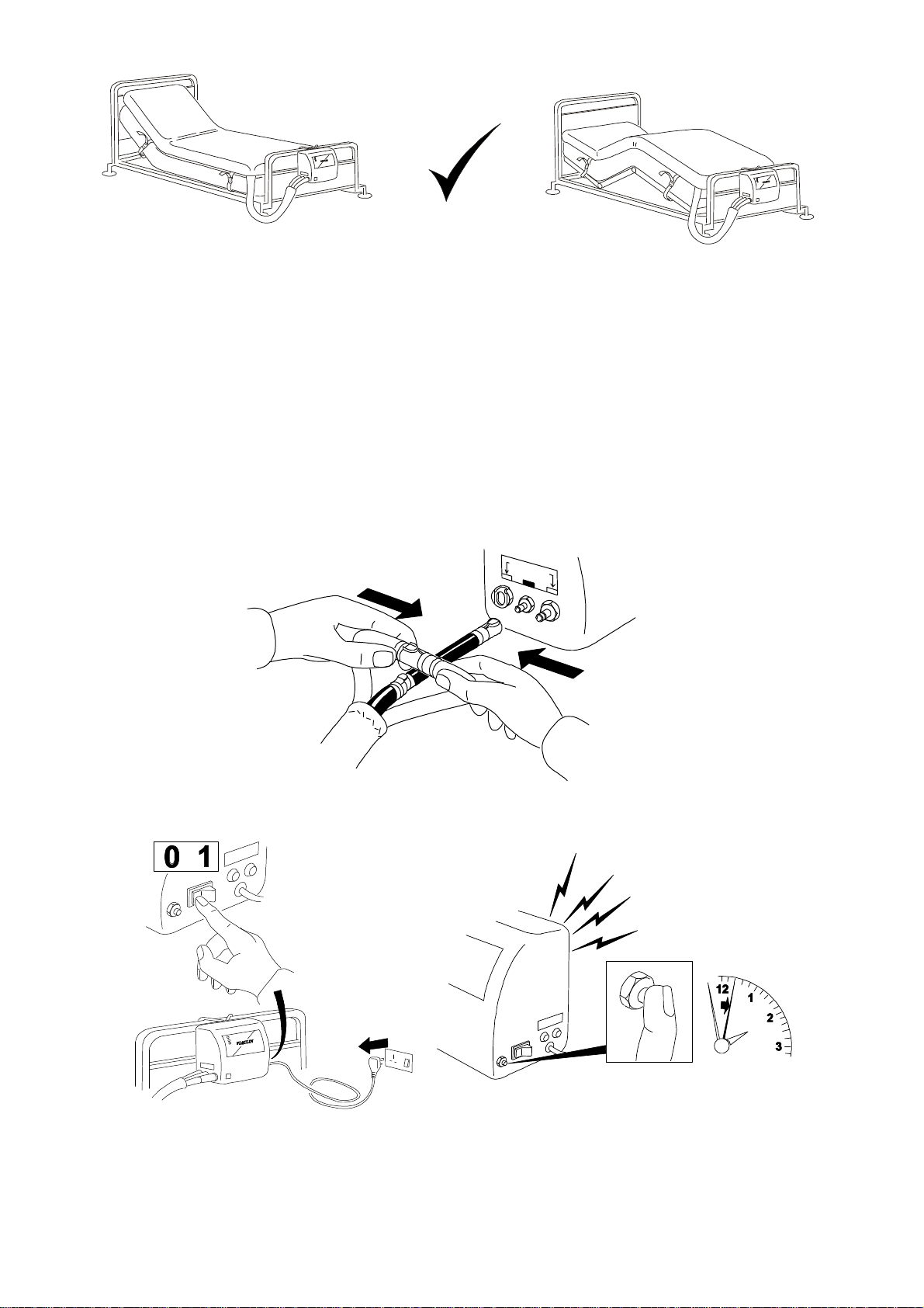
3.2 PROFILING AND KNEE-BREAKING
The system may be used while the bed is in the profiled or knee-break position:
1. With the bed in its present position, loosen or release the Overlay securing straps.
2. Change the bed to the required position (profile or knee-break).
3. Re-secure the securing straps.
NOTE: Straps must be attached to moving parts of the bed frame to avoid jamming the bed mechanism or stretching
the overlay.
12 111
10
9
8
7
2
3
4
5
6
Alternating Pressure Overlay
VIACLIN
!!ALARM!!

LFT5508 3.4Issue 3
VIACLIN MODEL 2502 Oct 02
3.3 MOVING THE BED AND POWER CUTS
CAUTION: The patient will not receive the benefit of the VIACLIN system while it is disconnected
and the power unit is switched off. Therefore the system should be reconnected as
soon as possible once the bed has been moved to its new position.
If you need to move the bed with the Mattress Overlay still inflated or in the event of a major mains power failure,
carry out the following procedure:
1. OVERLAY
aDisconnect the two red airpipes from the power unit and quickly connect together.
bDisconnect the black airpipe from the power unit.
2. POWER UNIT
aSwitch off and reset the power-down alarm. Disconnect from the mains.
b. The overlay will remain inflated for over 24 hours. The bed can now be moved.

LFT5508 3.5Issue 3
VIACLIN MODEL 2502 Oct 02
3.4 CPR (CARDIO PULMONARY RESUSCITATION)
In the event of cardiac arrest, disconnect both red airpipes:
1. While system is operating normally,
disconnect from the power unit.
2. While moving the bed, disconnect
from each other.
3.5 DEFLATION, REMOVAL, CARRYING AND STORAGE
POWER UNIT
1. Switch off.
2. Silence alarm.
3. Disconnect from mains.
4. Disconnect all airpipes.
5. Remove from bed.
OVERLAY
1. Undo all securing straps.
2. Roll up the Overlay.

LFT5508 3.6Issue 3
VIACLIN MODEL 2502 Oct 02
3.6 ALARMS AND FAULT FINDING
ALARMS
The VIACLIN Alternating Pressure Mattress Overlay is equipped with a sophisticated set of alarm functions, these
alert the user to the status of the available mains supply and any mattress overlay defect.
In normal conditions with mains power available, the power unit turned on, the mattress overlay fully inflated and
alternating, the status light on the power unit front panel will be green.
If at any time the mains power should be removed from the power unit, an audible alarm will be heard. This audible
alarm may be cancelled by pressing the alarm reset button for approximately 2 seconds.
If the product develops a defect whilst in use, the status light will turn red and an audible alarm will be heard. This
alarm may be cancelled by turning the mains power switch on the side of the power unit to the OFF (O) position,
then pressing the alarm reset button for approximately 2 seconds.
FAULT FINDING.
SYMPTOM ACTION
No lights on power unit Check power unit is connected to the mains power supply
and that the power unit switch is turned to the ON (1)
position.
Status light red and alarm sounding, or alarm sounding
but no lights
Turn mains switch on power unit OFF, press alarm reset
button for approximately 2 seconds until alarm cancels, then
switch on again:
a. If the status light does not illuminate, mains power
to the power unit has been lost. Check that the
power unit is connected to the mains supply and
that the power unit switch is turned to the ON (1)
position
b. If the alarm clears then returns after approximately
12 minutes, check air connection between power
unit and mattress overlay, ensuring that all air
connectors are pushed fully home and that the
airpipe is not folded or bent causing air flow to be
reduced. Turn mains switch on power unit OFF,
press the alarm reset button for approximately
2seconds until alarm cancels, then switch on again
Mattress overlay not inflating, status light green Check all air pipes as in (b) above

LFT5508 4.1Issue 3
VIACLIN MODEL 2502 Oct 02
SECTION 4 – CONSTRUCTION OF PRODUCT
4.1 MAJOR ELEMENTS OF SYSTEM
The product comprises two major elements:
1. Mattress Overlay
2. Power Unit
4.2 MATTRESS OVERLAY
The mattress has 18 transverse cells interconnected, such that there are 2 sets of cells - each being fully inflated then
fully deflated.
The cells are chemically bonded to pneumatic tubing, which is formed into a harness terminated by the CPR
connector.
The Mattress has a cover which protects the mattress and the bed base from soiling by body fluids, and has a smooth
surface finish to facilitate cleaning.
4.3. POWER UNIT
The Power Unit comprises a housing that has a moulded lid, a base and chassis assembly that is fixed together by four
socket-headed screws that also secure the hook assembly. When closed the casing is sealed to IP44.
The lid incorporates the following:
1. Mains switch - A double-pole, switch mounted the side wall of the casing.
2. Alarm reset button - Fixed adjacent to the mains switch.
3. Fuses - Two 1 Amp, anti surge fuses are fitted adjacent to the mains switch.
4. Air connectors - There are three connectors to enable connection of the airpipe fitted to the opposite side
wall of the casing to that used for the mains switch.
5. Front panel label - The label has a hole for the tri-coloured LED that indicates power supply on (amber),
normal running mode (green) and fault (red). The LED is connected to the integral electronic control unit
(ECU) via an IDT connector.

LFT5508 4.2Issue 3
VIACLIN MODEL 2502 Oct 02
The base incorporates the following:
1. Suspension hooks - To enable the unit to fit over the footboard of a bed.
2. Air intake holes - Covered on the inside by a small block of foam that serves as a primary air filter and
protects the unit from ingress of dust.
A manufacturer's label is affixed to the rear of the base which bears electrical rating information and the serial number
of the unit.
The interior of the base carries a mild steel chassis that is secured to the casing front by two screws.
The chassis incorporates the following:
Compressor ECU
Rotorvalve Silencer / Accumulator
Pressure Switch Restrictor Block
Alarm Buzzer

LFT5508 4.3Issue 3
VIACLIN MODEL 2502 Oct 02
4.4 TECHNICAL DETAILS
Cycle Control Purpose designed distributor valve supplying operating air to the
inflatable cells
Cycle Time 12 minutes
Supply Voltage 220/240Vac 50Hz
Power Rating 40VA
Fuse Rating Power Unit: 1A Antisurge (x2)
Mains Plug: 3A
Noise Level NC30
Nominal Dimensions Mattress (Inflated) Mattress (narrow)
Length: 1900mm Length 1900mm
Width: 880mm Width 800mm
Height: 130mm Height 130mm
Weight: 3.8kg Weight 3.5kg
Power Unit
Height: 203mm
Width: 220mm
Depth: 115mm (max)
Weight: 2.3kg
Electrical Safety Conforms to BSEN 60601-1
Classification Class 1, Type B
Mode of Operation Continuous
Symbols Alternating Current
Mains Switch -1 (On) Power connected to the mains supply
0 (Off) Power disconnected from mains supply
Type B
Environment (Usage and Storage) Air Humidity: 30% to 75%
Ambient Temperature: 0ºC (32ºF) to 40ºC (104ºF)
EMC This equipment complies with EMC requirements. If effects are
noticed the affected equipment should be moved apart.

LFT5508 5.1Issue 3
VIACLIN MODEL 2502 Oct 02
SECTION 5 – INFECTION CONTROL/CLEANING
5.1 INFECTION CONTROL
Infection Control and routine cleaning must be carried out in accordance with your local Infection Control Policy.
5.2 CLEANING GUIDELINES
WARNING: ENSURE THE POWER UNIT IS DISCONNECTED FROM THE MAINS ELECTRICITY
SUPPLY BEFORE CLEANING.
CAUTION Do not immerse the power unit in water.
Do not high temperature autoclave, or use Phenolic based products for cleaning.
It is recommended the system is cleaned between users or approximately every 2 weeks if in constant use.
Overlay and Cover
Wipe down with warm water containing detergent, dry thoroughly before use.
The cover may also be machine washed (80ºC).
Swab with a solution of Sodium Hypochlorite or similar (1,000 to 10,000ppm available chlorine), dry thoroughly before
use.
It is recommended that the system is cleaned regularly and after each patient use.
In many cases it will only be
necessary to remove the
overlay cover for cleaning.
Where there is obvious
soiling, a full cleaning or
sterilization procedure will
have to be carried out.
Ensure overlay and cover are
fully dry before use
CAUTION:
80 C
SODIUM
HYPOCHLORITE
(1,000 - 10,000
PARTS PER
PARTS PER
MILLION
AVAILABLE
DECONTAMINATE
USING ETO
(ETHYLENE OXIDE)
OR DRAEGER
SYSTEM
COVERS ONLY
PHENOL
C
A
U
T
I
O
N

LFT5508 5.2Issue 3
VIACLIN MODEL 2502 Oct 02
Power Unit
Wipe down with warm water containing detergent, dry thoroughly before use.
Wipe down with a solution of Sodium Hypochlorite or similar (up to 10,000ppm available chlorine), dry thoroughly
before use
Cleaning procedure
CAUTION:
The overlay mattress, overlay cover and power unit may also be decontaminated by using ETO (Ethylene Oxide) or the
Draeger method.
CAUTION
+
SODIUM
HYPOCHLORITE
(1,000 - 10,000
PARTS PER
MILLION
AVAILABLE
CHLORINE (Cl))
DECONTAMINATE
USING ETO
(ETHYENE OXIDE)
OR
DRAEGER
SYSTEM
PHENOL
C
A
U
T
I
O
N

LFT5508 6.1Issue 3
VIACLIN MODEL 2502 Oct 02
SECTION 6 – EQUIPMENT MAINTENANCE
The item numbers shown at the top left hand corner of the box drawn around each item are used in the Maintenance
and Parts sections for identification purposes, i.e. Item 1 in each section is the ECU, Item 2 is the compressor, etc.
'A'Cells
'B'Cells
Overlay
Side Formers
To
Atmosphere
From
Atmosphere
Supply
Voltage
A.C.Supply
Motor
Gearbox
SupplyVoltage
Rotorvalve
Alarm
ECU
PL2
PL1
PL3
PL6
PL4
PL5
Pressure
Switch
Buzzer
Tri-Colour
LED
Restrictor
Block
Compressor
MainsOn/Running Normally
Air
Connector
Alarm
Reset
1
23
4
5
6
78

LFT5508 6.2Issue 3
VIACLIN MODEL 2502 Oct 02
Notes:
i. It is recommended that the Viaclin system is part of a planned preventative maintenance scheme.
ii. To prevent damage, normal electrostatic control procedures must be observed when working on the Power
Unit.
iii. Electrical safety checks must be carried out on completion of any routine maintenance or workshop repairs.
iv. Details of tubing in the power unit is shown in Section 8 ‘TUBING DETAILS – SCHEMATIC’
Power Unit – General
ECU Conn N/A
Maint/Repair 1. Check the security of the wiring and tightness of screws and integrity of component mountings -
rectify as necessary.
2. Check pneumatic tubing for hardening or cracking and replace as necessary.
3. Switch on the electrical power supply.
4. Check all pneumatic connections for air leaks and rectify as necessary.
5. Lubricate spigot outlets sparingly with appropriate grease.
Test/Set-Up Carry out an overall operation test
Test Eqpt N/A
Item 1 – Electronic Control Unit
The microprocessor controlled ECU is mounted on the chassis.
The ECU has a rechargeable battery that provides power for the ECU and alarm buzzer in the event of power failure
(it does not provide reserve power for the compressor or rotorvalve). The battery can only be recharged by the
ECU.
Control of the compressor is by the ECU, in response to signals provided by the pressure switch which continually
monitors system pressures.
The ECU also controls the status indicator on the front panel and the alarm buzzer and responds to activation of the
alarm-reset pushbutton.
ECU Conn N/A
Maint/Repair The battery is the only maintainer serviceable item; otherwise the ECU is repair by replacement.
Note: To prevent damage, normal static control procedures must be observed when working on the
PMU.
Battery replacement (replacement only needed if battery is charged and power down alarm fails)
1. Unsolder battery from ECU – note orientation of battery.
2. Solder new battery onto ECU, ensuring it is in the same orientation as the old battery.
Test/Set-Up Testing of the ECU is carried out as part of the system test
Test Eqpt N/A

LFT5508 6.3Issue 3
VIACLIN MODEL 2502 Oct 02
Item 2 – Compressor
One Air Compressor is fitted, which takes air from atmosphere within the power unit and delivers air to the overlay
bottom deck via the silencer, restrictor block, airpipe and to the top deck via the silencer, restrictor block rotorvalve
and airpipe
The Compressor has rubber-mounting feet attached by screws and nuts to an aluminium baseplate, a 4-way IDT
connector for connection to the ECU, a spigot outlet over which 8mm-diameter silicone tubing is push-fitted to
enable pneumatic connection to the check valve, from which tubing connects to the silencer.
ECU Conn PL4
Maint/Repair Maintenance of the compressor consists of replacing the filter:
1. Remove the filter cover from the end of the compressor, remove the filter.
2. Clean the filter housing surfaces and the disk.
3. Fit a new filter and replace the cover.
Test/Set-Up Carry out compressor electrical tests:
1. Disconnect tubing from the compressor (if fitted).
2. Connect the compressor to the appropriate connector(s) on the test set (TE5315).
3. Connect the test set to mains and switch on.
No-Load Test
Check compressor runs with no excess vibration or noise - if there is a defect the 1.6a fuse may
blow.
On-Load Test
This test is carried out at the same time as the flow rate test.
Carry out a compressor flow rate test with TE5315 connected as for the no-load test - if there is
a Defect the 1.6a fuse may blow.
Carry out a flow rate test on the compressor:
Note:Ensure the compressor is in its ‘HOT’ state prior to carrying out the test:
Start Service Mode and press the Alarm Reset button once, this will start the compressor. Let the
compressor run for 30 minutes to get to the 'Hot' state.
If the system has been running for at least 1 hour prior to starting Service Mode, the compressor
is assumed to be in the 'Hot' state and do not need to be run for 30 minutes.
1. Remove the tubing from the compressor and connect the test equipment (TE4540) in its place.
Note:Ensure Test Equipment is connected to the pressure outlet of the compressor, not the vacuum
side.
2. Switch the power unit On. Adjust the aneroid sphyg to read 100mmhg.
3. Check the flow rate on the flow meter reads not less than 5.5 ltr/min. If using test equipment
other than TE4540, the flow rate should read 7 ltr/min or greater.
4. Switch off, remove test equipment; reconnect the tubing to the compressor.
Notes: i. If using a 1-12 ltr glass tubed flow meter, read the value from the top of the float.
ii. If using a plastic bodied flow meter, read the value from the centre of the float.
Test Eqpt TE4540, TE5315

LFT5508 6.4Issue 3
VIACLIN MODEL 2502 Oct 02
Item 3 - Silencer
The silencer smoothes pressure fluctuations in the pneumatic system and absorbs any noise being carried in the
airflow from the compressor.
It is fitted into a recess in the chassis and held in place by the casing.
Spigot outlets from the silencer have 8mm-diameter silicone tubing push-fitted to enable pneumatic connection to the
compressor and restrictor block.
ECU Conn N/A
Maint/Repair 1. There are no maintenance actions to be carried out on the silencer. Repair is by replacement
2. It is recommended the silencer is replaced annually
Test/Set-Up There are no tests to be carried out on the silencer.
Test Eqpt N/A
Item 4 – Restrictor Block
The restrictor block enables airflow to and from the following:
Silencer
Pressure Switch
Air Connector (for side formers only)
Rotorvalve
ECU Conn N/A
Maint/Repair Remove all tubing from restrictor block and ensure all spigots are clear of obstructions.
Test/Set-Up There are no tests to be carried out on the restrictor block.
Test Eqpt N/A
This manual suits for next models
1
Table of contents