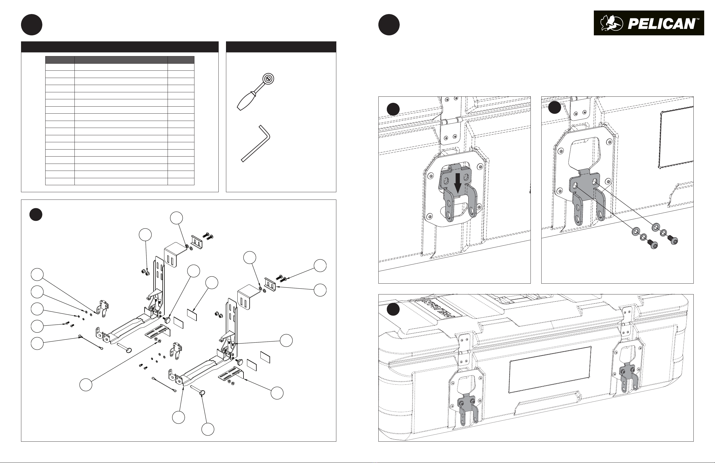
manuals.online logo
Brands
  1. Home
  2. •
  3. Brands
  4. •
  5. Pelican
  6. •
  7. Automobile Accessories
  8. •
  9. Pelican UNIVERSAL SDDLMT2A User manual

Pelican UNIVERSAL SDDLMT2A User manual

READ ME!
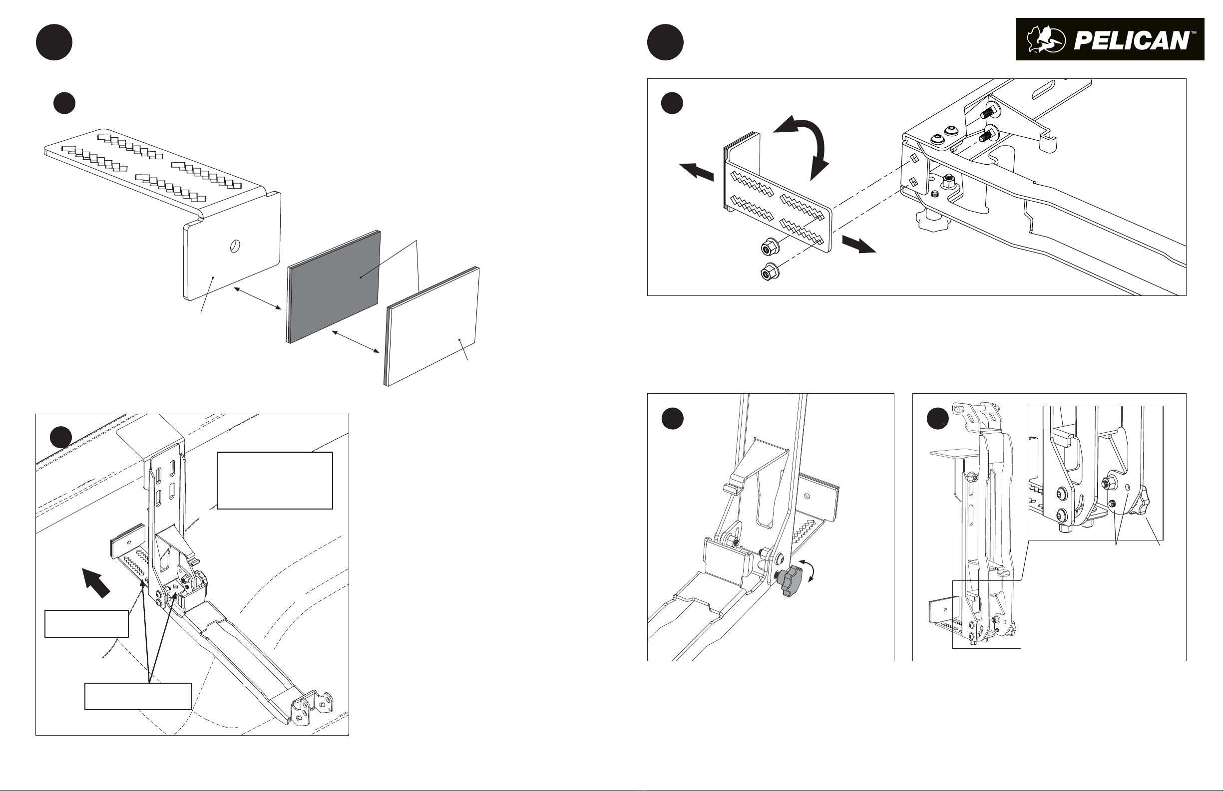
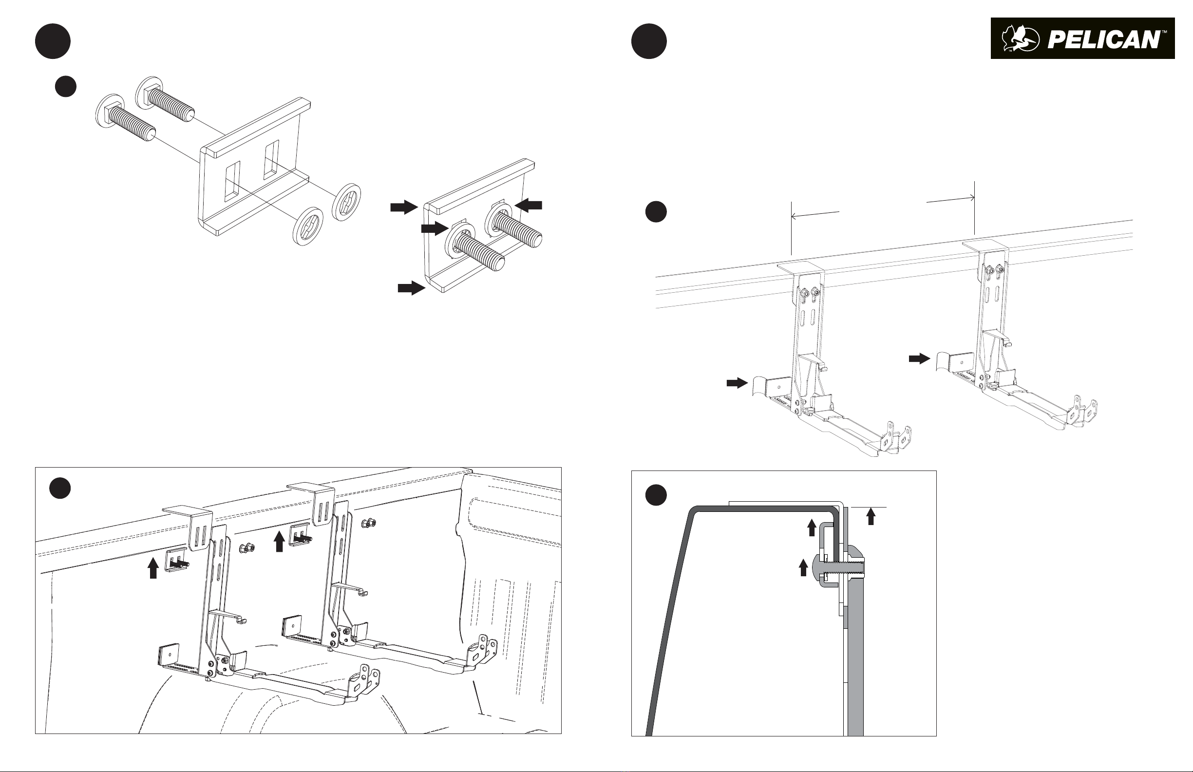
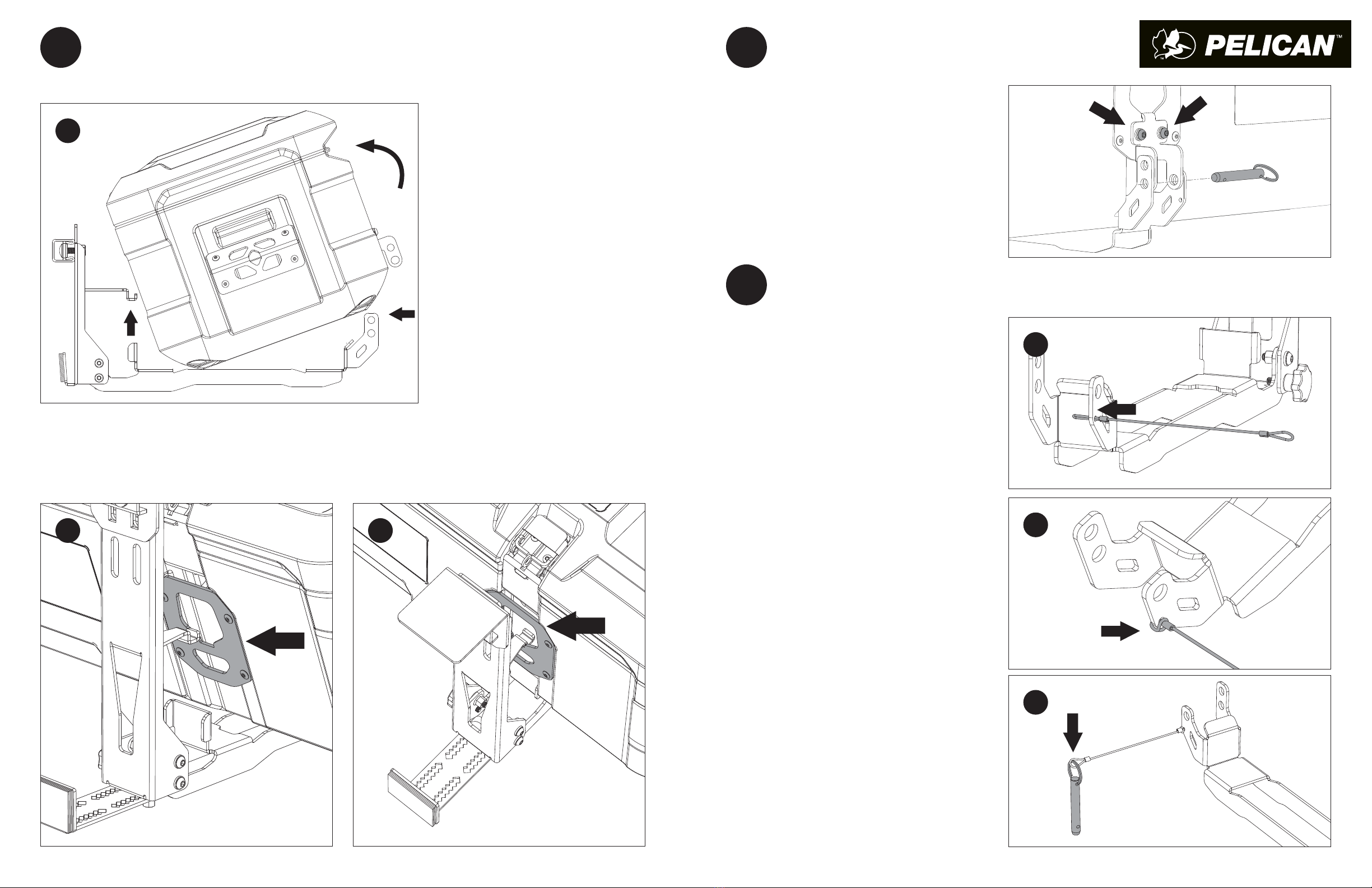
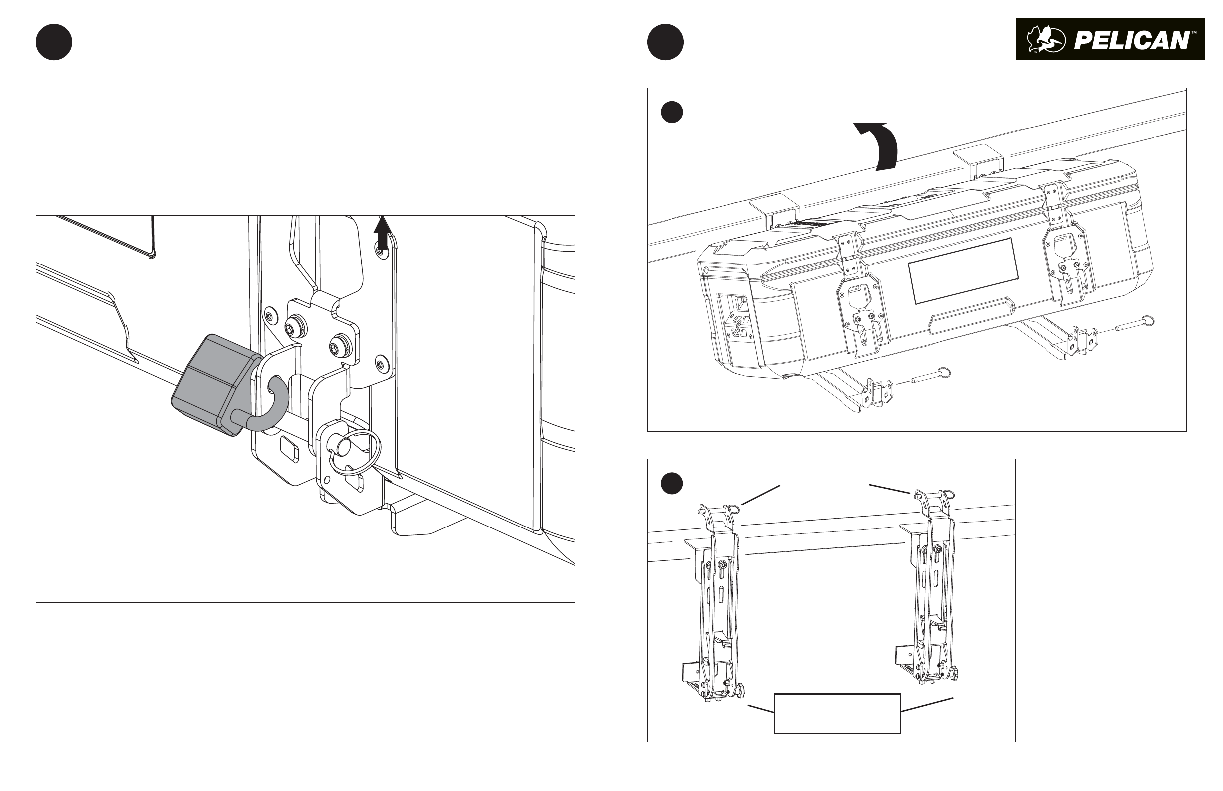
• NOTE: CASE MAY BE MOUNTED ON HINGE OR LATCH SIDE, ACCORDING TO ACCESS PREFERENCE- FROM OUTSIDE OR MIDDLE OF RACK.
THANK YOU FOR PURCHASING A PELICAN™ CARGO CASE SADDLE MOUNTING KIT. BEFORE YOU START, TAKE A MOMENT TO FAMILIARIZE
YOURSELF WITH THE FITTING INSTRUCTIONS AND THE COMPONENTS RECEIVED. REFER TO PAGE 1 FOR A LIST OF ALL THE COMPONENTS,
QUANTITIES AND TOOLS REQUIRED.
SINCE 1976
PELICAN™ CARGO CASE
SADDLE MOUNT, FLANGE, GEN 2 (SDDLMT2A)
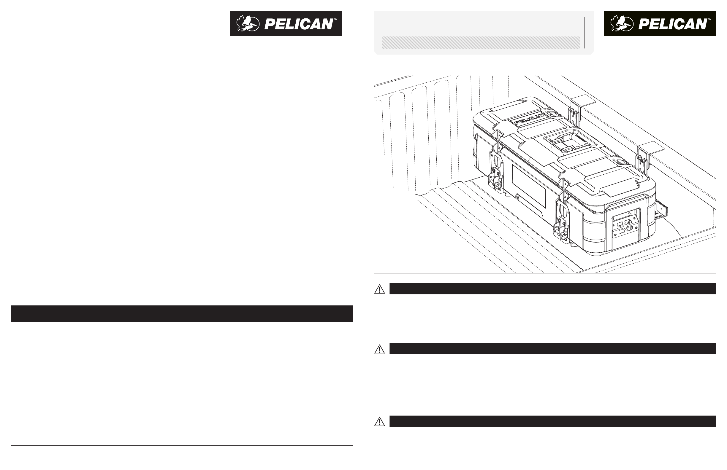
For Pelican™ BX55S, BX85S CARGO Cases in Truck Beds using factory bed-rail mounting.
PELICAN PRODUCTS, INC.
23215 Early Avenue, Torrance, CA 90505
Pelican.com • 310.326.4700
IMPORTANT WARNING!
LATCHES AND MOUNTING KIT CARE
It is critical that Pelican™ Cargo Mounts and Cases be properly installed and securely attached to your vehicle. Failure to properly secure
the Mounts and Cargo Cases to your vehicle could result in serious injury and even death. You are responsible for the fitment of the Mounts
and Cargo Cases to your vehicle. You must therefore periodically inspect the equipment for wear and damage. Replace if in doubt. If you have
limited mechanical experience you should not attempt to install the equipment. You should have the equipment installed by a professional
installer if you have any doubts about your abilities.
It is imperative that the user check the fit security of the cases to the vehicle after an initial brief period of driving and adjust if required.
Pelican recommends the user do so periodically and if road conditions change (i.e. freeway to dirt "road"), again check the fit security of the
attachment of the Case to the vehicle.
Periodically check the latches and mounting hardware to ensure there are no loose parts. Continual exposure to daylight may cause the black hardware
finish to dull. To maintain the glossy finish, occasionally apply a light coat of UV protectant. After exposure to salty coastal climates or snowy regions,
rinse off the mounts with water to remove salt deposits. To help prevent corrosion, apply a non-reactive silicone-based oil or spray to nuts and bolts.
Take care not to damage painted surfaces during mounting and dismounting. Touch-up paint is recommended as needed to prevent corrosion.
Pelican Products, Inc. (“Pelican”) guarantees its Pelican™ Cargo cases for a lifetime against
breakage or defects in workmanship. This lifetime warranty does not cover mounting hardware,
which Pelican warrants against defects in materials and workmanship for three years from the date
of purchase. To the extent permitted by law, Pelican’s liability is limited to the case and not its
contents and in no event shall Pelican’s liability to the purchaser for damages exceed the purchase
price of the case in respect of which damages are claimed.
TO THE EXTENT PERMITTED BY LAW: (A) THIS WARRANTY IS IN LIEU OF ALL WARRANTIES, EXPRESS
OR IMPLIED, INCLUDING, BUT NOT LIMITED TO, THE IMPLIED WARRANTIES OF MERCHANTABILITY
AND FITNESS FOR A PARTICULAR PURPOSE; (B) ALL OTHER IMPLIED WARRANTIES AND ANY LIABILITY
NOT BASED UPON CONTRACT ARE HEREBY DISCLAIMED AND EXCLUDED; AND (C) IN NO EVENT SHALL
PELICAN BE LIABLE FOR ANY INDIRECT, PUNITIVE, INCIDENTAL OR CONSEQUENTIAL DAMAGES, OR
SPECIAL DAMAGES, REGARDLESS OF WHETHER A CLAIM FOR SUCH DAMAGES IS BASED ON WARRANTY,
CONTRACT, NEGLIGENCE OR OTHERWISE .
With valid dated proof of purchase, Pelican will either repair or replace any broken or defective
product, at our sole option. Certain products are available for a limited time only. If a claim is made
involving one of these products, Pelican reserves the right to replace a broken or defective product
with a standard Pelican product of comparable size and quality if no comparable limited edition
product is available at the time of a claim. TO THE EXTENT PERMITTED BY LAW, THIS SHALL BE THE
SOLE AND EXCLUSIVE REMEDY OF THE PURCHASER.
To make a warranty claim, the purchaser must complete the warranty claim form at
https://www.pelican.com/us/en/support/warranty/. Any warranty claims shall be made by the
purchaser as soon as practicable and, with respect to the mounts and related hardware, no later
than three years from the date of purchase. The purchaser must provide valid dated proof of purchase
and obtain a return authorization number from Pelican Customer Service prior to returning any
product, and is responsible for paying for all warranty freight costs. If Pelican determines that any
returned product is not defective, within the terms of this warranty, the purchaser shall pay Pelican
all costs of handling, return freight and repairs at Pelican’s prevailing rates.
This warranty does not cover normal wear and tear including but not limited to scratches, dents
or tears, aesthetic surface damage which may be caused by oxidation or by the natural breakdown
of colors caused by exposure to the elements. All warranty claims of any nature are barred if the
product has been altered, damaged or in any way physically changed, or subjected to abuse, misuse,
negligence or accident.
Some states and countries do not allow limitations on how long an implied warranty lasts or the
exclusion or limitation of incidental or consequential damages, so the above limitation or exclusion
may not apply to you. This warranty gives you specific legal rights, and you may have other rights
which vary from state to state and country to country.
In Australia: The benefits provided to you under this warranty are in addition to your rights and
remedies as a consumer under the Australian Consumer Law as contained in the Competition and
Consumer Act 2010 (Cth) (“the Act”). Nothing in this warranty limits the rights or obligations of a
party under the Act in relation to the supply to consumers of goods which cannot be limited, modified
or excluded. If applicable, our goods come with guarantees that cannot be excluded under the Act.
Consumers are entitled to a replacement or refund for a major failure and compensation for any other
reasonably foreseeable loss or damage. Consumers are also entitled to have the goods repaired or
replaced if the goods fail to be of acceptable quality and the failure does not amount to a major
failure. If you are not a consumer under the Act, then your rights may be limited. To make a warranty
claim, the purchaser may contact Pelican Products Australia, Suite 2.33, West Wing, Platinum Bldg.,
Erina NSW 2250, Tel: +612 4367 7022, or email: info[email protected]. Any claims should be
made as soon as practicable. To expedite claims, the purchaser should obtain a return authorization
number from Pelican Customer Service prior to returning any product. The purchaser is responsible
for paying for all freight costs. If Pelican determines that any returned product is not defective,
within the terms of this warranty or the Act, the purchaser may pay Pelican all costs of handling,
return freight and repairs at Pelican’s prevailing rates. In the event that Pelican determines that
any returned product is defective, within the terms of this warranty or the Act, Pelican shall pay the
purchaser all reasonable costs of the purchaser in making a claim under this warranty.
PELICAN™ CARGO CASES AND MOUNTS
LIMITED LIFETIME WARRANTY (CASES) AND THREE YEAR WARRANTY (MOUNTS)
©2021 Pelican Products, Inc. Part No. SDDLMT-002A-BLK Rev. A DE21 5-36255
All trademarks are registered and/or unregistered trademarks of Pelican Products, Inc., its subsidiaries and/or affiliates.
For warranty details go to www.pelican.com/warranty
UNIVERSAL
16
17
13
10
14
11
15
5
12
3
1
6
4
7
9
8
2
PARTS LIST
1
1.1
GET ORGANIZED
ITEM NO. DESCRIPTION QT Y.
1 SADDLE MOUNT BRACKET SUBASSEMBLY, FLANGE 2
2 CASE PLATE CLAMP 2
3 QUICK-RELEASE PIN 2
4 LANYARD 2
5 M6-1.0 X 16 CARRIAGE BOLT 4
6 M6-1.0 NYLON LOCK FLANGE NUT 4
7 M6-1.0 X 14 BUTTON HEAD HEX DRIVE SCREW 4
8 M6 FLAT WASHER 4
9 M6 SPLIT LOCK WASHER 4
10 L-BRACKET 2
11 FLANGE CLAMP 2
12 FOOT 2
13 DUAL-LOCK SNAP STRIP, ADHESIVE BACK 4
14 M8 X 30 CARRIAGE BOLT 4
15 M6 NYLON RETAINER WASHER 4
16 M8 NYLON LOCKNUT 
17 THREADED DETENT KNOB 2
TOOLS REQUIRED*
M4 ALLEN KEY/ DRIVER
M10, M13 WRENCH/SOCKET
* Tools not included.
2INSTALL CASE PLATE CLAMPS
PREFERRED MOUNTING IS ON HINGED SIDE OF CASE,
FOR OPENING CASE LID FROM OUTSIDE OF TRUCK BED.
USING M4 ALLEN DRIVE TOOL, ASSEMBLE CLAMPS TO PLATES USING
M6 SCREWS, WITH LOCK WASHERS AND FLAT WASHERS AS SHOWN.
PARTIALLY TIGHTEN SCREWS TO ALLOW FINAL ADJUSTMENT.
REPEAT FOR 2ND MOUNTING PLATE ON SAME SIDE OF CASE.
2.1 2.2
2.3
1 2
3ASSEMBLE AND ADJUST FEET
PRESS TWO (2) BLACK SNAP FACES TIGHTLY TOGETHER.
REMOVE TAPE LINER ON ONLY ONE SIDE.
ENSURE MOUNTING FOOT SURFACE IS CLEAN
AND DEGREASED. LINE UP TAPE SQUARE TO FOOT.
PRESS THIS ADHESIVE FACE FIRMLY ON ADJUSTABLE FOOT.
LEAVE TAPE LINER ON OTHER SIDE FOR NOW.
TAKE CARE TO NOT TOUCH ADHESIVE SURFACE
WITH HANDS OR OBJECTS.
TEMPORARILY HOLD SADDLE ARM IN
TRUCK BED TO DETERMINE FOOT LENGTH
ADJUSTMENT.
THIS MAY VARY BETWEEN THE TWO SADDLE
ARMS, OR NEED FINE ADJUSTMENT LATER.
INSERT DETENT KNOB WITH LOWER ARM HORIZONTAL
KNOB MUST BE THREADED FULLY IN, TO LOCK ARM HORIZONTALLY FOR SUPPORTING CASE.
REPEAT STEPS 3.1 - 3.4 FOR OTHER MOUNT SUBASSEMBLY.
TO AVOID SCRATCHING PAINT ON LOWER ARM, TAKE CARE TO ALWAYS UNTHREAD KNOB
SUFFICIENTLY TO CLEAR LOWER ARM BEFORE ROTATING.
3.4
DETENT KNOB
(Right Hand Thread)
Foot resting on wall.
Flip over if needed.
Note which slot positions
will be used for bolts.
Place L-bracket on rail in
desired case location.
Hold saddle arm against it
with lower arm horizontal.
Place foot against bed wall.
3.2
3.1
Remove the adhesive liner.
Firmly press adhesive side
to face of mounting foot.
Snap black faces together tightly.
Leave this adhesive liner in
place until later step, for
final adjustments of mount.
FIT M6 BOLTS THROUGH SQUARE HOLES IN SADDLE ARM.
PARTIALLY TIGHTEN M6 LOCKNUTS, FOR FINAL ADJUSTMENT LATER.
Adjust to bed wall
and level the case.
Flip foot over
if required to
fit bed wall.
3.3
3.5
VERTICAL: STOWED
DETENT
HOLES
KNOB
Lower arms have two (2) detent
holes that must be used for
locking in position:
One hole in horizontal position
to support case; one vertical, to
stow case (not-in-use).
3ASSEMBLE AND ADJUST FEET
3 4
4MOUNT SADDLE ARM SUBASSEMBLIES
TO TRUCK BED RAIL
4.4
4.3
DETERMINE LOCATION ALONG RAIL FOR CASE.
ADJUST SADDLE ARMS TO MATCH THE MOUNTING PLATE SPACING OF YOUR CASE.
CLEAN AND DEGREASE BED WALL BEHIND SADDLE MOUNT FEET.
PEEL OFF TAPE LINERS TO ADHERE FEET TO BED WALL IN FINAL POSITION.
PUSH FEET FIRMLY AGAINST BED WALL TO ENSURE TAPE ADHESION AND SNAP STRIP MATING.
THIS WILL ASSIST IN HOLDING SADDLE ARMS FOR STEP 4.4.
SLIDE FLANGE CLAMPS AND BOLTS UP AS HIGH
AS POSSIBLE ON BED-RAIL.
HOLD SADDLE ARM IN FINAL POSITION AND
TIGHTEN M8 NUTS TO SECURE.
4.2
BX55S = 19.5 IN
BX85S = 39 IN
4ASSEMBLE FLANGE CLAMPS
ASSEMBLE TWO (2) M8 X 30
CARRIAGE BOLTS THROUGH
SLOTS IN FLANGE CLAMP TO
NYLON RETAINER WASHERS.
SLIDE NYLON RETAINER WASHERS FIRMLY AGAINST FLANGE CLAMP
AND TIGHTLY SEAT SQUARE BOLT FEATURES IN SLOTS AS SHOWN.
*NOTE LEG “B” IS SHORTER THAN “A” AND SHOULD BE AT TOP WHEN
INSTALLED IN TRUCK. FLANGE SLOTS WILL BE TOWARDS BOTTOM.*
REPEAT FOR OTHER MOUNT SUBASEMBLY.
REST L-BRACKETS ON BED RAIL.
SLIDE FLANGE CLAMP ASSEMBLIES UP BEHIND RAIL FLANGE.
ADJUST VERTICAL SADDLE ARM SLOTS FOR CASE HEIGHT AND WHEEL WELL CLEARANCE.
FIT BOLTS THROUGH SLOTS IN L-BRACKETS AND SADDLE ARMS.
PARTIALLY TIGHTEN M8 LOCKNUTS TO ALLOW FINAL ADJUSTMENT.
4.1
B
A
5 6
6
7
ADJUST AND TIGHTEN PLATE CLAMPS
ASSEMBLE LANYARDS TO LOWER SADDLE ARMS
1. WITH PIN INSERTED AND FASTENERS LOOSENED,
ADJUST PLATE CLAMP POSITION TO CENTER
AND ALLOW EASY PIN REMOVAL/INSERTION.
2. TIGHTEN SCREWS WITH M4 ALLEN TOOL.
1. SQUEEZE END OF LANYARD AND PUSH
THROUGH HOLE IN PINNED YOKE.
2. FEED OTHER END BACK THROUGH LOOP.
PUSH PAST CRIMP EDGE TO SECURE, AS
SHOWN.
3. ATTACH LOOSE END TO KEY-RING OF QUICK
RELEASE PIN. REPEAT FOR OTHER LANYARD. 7.3
7.1
5
5.2 5.3
LOADING CARGO CASE ON SADDLE MOUNTS
CLEARING REAR HOOKS CHECK BOTH REAR HOOKS ARE NOW ENGAGED
5.1
TILT CASE 20 DEGREES AND LOWER
REAR EDGE TO REST ON SADDLE ARMS.
BY CLEARING THE ARMS AT
THE FRONT, THE REAR HOOKS
WILL ALSO CLEAR THE PLATES.
SLIDE CASE BACK AGAINST
UPRIGHTS TO ENGAGE HOOKS.
TILT CASE DOWN TO REST IN
HORIZONTAL POSITION.
7.2
7 8
9CASE REMOVAL
SLIDE PINS OUT AND
TILT CASE UP AND OUT.
UNTHREAD DETENT KNOBS
SUFFICIENTLY TO CLEAR
LOWER ARMS.
SWING ARMS UP TO THE
VERTICAL POSITION.
LOCK BY FULLY THREADING
KNOBS BACK IN.
REPLACE PINS IN ARMS.
NOW STOWED OUT OF WAY.
Replace pins for storage
TO SECURE CARGO CASE
AGAINST THEFT
PADLOCK ONE OR BOTH MOUNTS
(PADLOCK SOLD SEPARATELY).
8LOCKING THE CASE
9.1
9.2
Unthread knobs to clear holes
in lower arms. Fold arms up.
Thread back in to lock vertically.
910

This manual suits for next models

2

Other Pelican Automobile Accessories manuals

Pelican S15609 User manual

Pelican

Pelican S15609 User manual

Pelican XBDMT5-001B-BLK User manual

Pelican

Pelican XBDMT5-001B-BLK User manual

Pelican XBEDMT2 User manual

Pelican

Pelican XBEDMT2 User manual

Pelican SDDLMT2B User manual

Pelican

Pelican SDDLMT2B User manual

Popular Automobile Accessories manuals by other brands

Blaupunkt CAN-Interface RCI-4A-VW manual

Blaupunkt

Blaupunkt CAN-Interface RCI-4A-VW manual

banks iDash 1.8 quick start guide

banks

banks iDash 1.8 quick start guide

Acewell CA-085-15X user manual

Acewell

Acewell CA-085-15X user manual

Reese Elite Pop-In Assembly instructions

Reese

Reese Elite Pop-In Assembly instructions

DV8 LPBR-02 installation manual

DV8

DV8 LPBR-02 installation manual

B&G electronics PW-150 Installation and operation manual

B&G electronics

B&G electronics PW-150 Installation and operation manual

SnowEx SP-8500 manual

SnowEx

SnowEx SP-8500 manual

Jeep TTJL-01 quick start guide

Jeep

Jeep TTJL-01 quick start guide

Pandora 3126 installation manual

Pandora

Pandora 3126 installation manual

Fortin EVO ALL manual

Fortin

Fortin EVO ALL manual

iDataLink Maestro RR instruction manual

iDataLink

iDataLink Maestro RR instruction manual

DU-HA DU-HOOKY Assembly instructions

DU-HA

DU-HA DU-HOOKY Assembly instructions

Cruz Evo Rack Pro P18-110 Assembly instructions

Cruz

Cruz Evo Rack Pro P18-110 Assembly instructions

Syvecs Polaris RZR Pro R Plug in Ecu manual

Syvecs

Syvecs Polaris RZR Pro R Plug in Ecu manual

Bestop powerboard nx installation instructions

Bestop

Bestop powerboard nx installation instructions

Nav TV MBUX-RVC instruction manual

Nav TV

Nav TV MBUX-RVC instruction manual

volkano Turbocharger Series instruction manual

volkano

volkano Turbocharger Series instruction manual

Safe Fleet PRIME DESIGN CBR 0011 quick start guide

Safe Fleet

Safe Fleet PRIME DESIGN CBR 0011 quick start guide

manuals.online logo
manuals.online logoBrands
  • About & Mission
  • Contact us
  • Privacy Policy
  • Terms and Conditions

Copyright 2025 Manuals.Online. All Rights Reserved.