Pelpro PP130 User manual

7086-171D • July 10, 2014 www.pelprostoves.com1
This heater meets the U.S. Environmental Protection Agency’s emission limits for wood heaters sold after July 1, 1990.
PP130 Pellet Stove
Model(s):
PP130
WARNING
If the information in these instruc-
tions is not followed exactly, a fire
may result causing property damage,
personal injury, or death.
• Do not store or use gasoline or other flam-
mable vapors and liquids in the vicinity of this
or any other appliance.
• Do not overfire - If heater or chimney connec-
tor glows, you are overfiring. Overfiring will
void your warranty.
• Comply with all minimum clearances to com-
bustibles as specified. Failure to comply may
cause house fire.
Questions, problems, missing parts?
Before returning to your retailer, visit
www.pelprostoves.com or call customer
service at 877-427-3316.
HOT SURFACES!
Glass and other surfaces are hot
during operation AND cool down.
Hot glass will cause burns.
• Do not touch glass until it is cooled
• NEVER allow children to touch glass
• Keep children away
• CAREFULLY SUPERVISE children in same room as
fireplace.
• Alert children and adults to hazards of high temperatures
• High temperatures may ignite clothing or other
flammable materials.
• Keep clothing, furniture, draperies and other flammable
materials away.
WARNING
SAFETY NOTICE: PLEASE READ THIS ENTIRE MANUAL
BEFORE INSTALLATION AND USE OF THIS PELLET FUEL-
BURNING ROOM HEATER. FAILURE TO FOLLOW THESE
INSTRUCTIONS COULD RESULT IN PROPERTY DAMAGE,
BODILY INJURYOR EVEN DEATH. CONTACT LOCALBUILD-
ING OFFICIALSABOUT RESTRICTIONSAND INSTALLATION
INSPECTION REQUIREMENTS IN YOURAREA.
Owner’s Manual
Installation & Operation
INSTALLER: Leave this manual with party responsible for use and operation.
OWNER: Retain this manual for future reference.
NOTICE: SAVE THESE INSTRUCTIONS
NOTE
To obtain a French translation of this manual, please contact
your dealer or visit www.pelprostoves.com
Pour obtenir une traduction française de ce manuel, s’il vous
plaît contacter votre revendeur ou visitez www.pelprostoves.
com
O-T L
Tested and
Listed by Portland
Oregon USA
OMNI-Test Laboratories, Inc.
CUS
Report #: 061-S-88-2

7086-171D • July 10, 2014 www.pelprostoves.com2
QUICK START GUIDE
4.
Check all three baffles are
hooked into slots.
*Before you plug in this appliance, follow these instructions*
3.
Verfiy firepot’s orientation is
correct.
5.
Plug power cord into wall
receptacle.
*Green light will start flashing one
time per second*
NOTE: If the light does not change
to solid green, turn the control back
to off, unplug the appliance and
repeat steps 5 & 6.
7.
Stove will feed for two minutes.
*Green light will start blinking
continuously, to indicate startup
sequence*
NOTE: Allow the unit five
minutes for ignition to take place.
8.
Once a fire has been
established in the unit, leave
the unit burning on HI for 30
minutes to allow the paint to
cure.
NOTE: Odors and vapors released
during initial operation.
•Curing of high temperature paint.
•Open windows for air circulation.
*Odors may be irritating to
sensitive individuals.
9.
After 30 minutes have passed,
turn dial control to OFF, and
allow unit to cool completely.
Once unit has cooled, open
door and clean firepot according
to the cleaning instructions
found on the inside of the
hopper lid, or in the owners
manual.
*Unit is now ready to resume
normal operation*
6.
To prime the feed tube,
QUICKLY turn the dial control
from OFF to HI, back to OFF,
then back to HI.
*The light should stop blinking and
light up solid green*
NOTE: Priming is only required
the first time the appliance is lit,
or after the hopper has run
completely out of pellets.
If ignition is missed, empty the
firepot and repeat step 3.
1.
Turn Dial Control to OFF.
All material needs to
be removed from the
door glass and
firebox before
operation
2.
Add pellets to hopper and close
lid.
Back
Hole for Igniter
V
EL
Front
of
firepot
has
the lip
2
1
4
3567
8
9
10
LO
OFF HI
O
N
A
U
T
O
A
L
A
R
M
2
1
4
3567
8
9
10
LO
OFF HI
2
1
4
3567
8
9
10
LO
OFF HI
O
N
A
U
T
O
A
L
A
R
M
2
1
4
3567
8
9
10
LO
OFF HI

www.pelprostoves.com 7086-171D • July 10, 2014 3
TABLE OF CONTENTS
Safety Alert Key:
• DANGER! Indicates a hazardous situation which, if not avoided will result in death or serious injury.
• WARNING! Indicates a hazardous situation which, if not avoided could result in death or serious injury.
• CAUTION! Indicates a hazardous situation which, if not avoided, could result in minor or moderate injury.
• NOTICE: Indicates practices which may cause damage to the appliance or to property.
1 Listing and Code Approvals ............5
A. Appliance Certification......................................................5
B. Mobile Home Approved ....................................................5
C. Glass Specifications.........................................................5
D. Electrical Rating (On High)...............................................5
E. BTU & Efficiency Specifications........................................5
2 General Information..........................6
A. Fire Safety .........................................................................6
B. Non-Combustible Materials ...............................................6
C. Combustible Materials.......................................................6
D. Fuel Material and Fuel Storage........................................6
E. Before Your First Fire.......................................................6
3 General Operating Information.......7
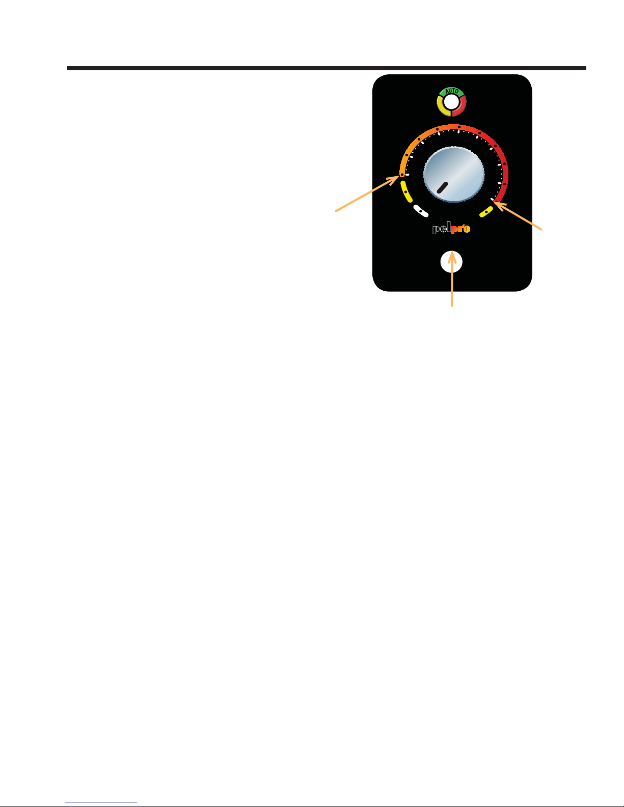
A. User Dial Control ...............................................................7
B. Filling the Hopper...............................................................7
C. Priming the Feed Tube......................................................7
D. Firepot Purge.....................................................................8
E. Shutdown...........................................................................8
F. Starting Your First Fire........................................................8
G. Fire Characteristics ...........................................................8
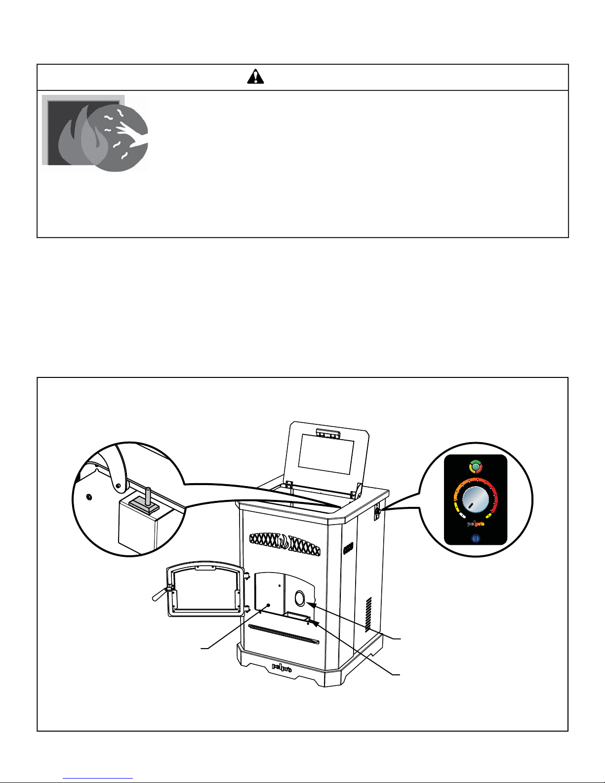
H. Your Pellet Appliance - General Operating Parts...............9
I. LED Color Coding Chart and Explanation..........................10
J. Ignition Cycles...................................................................11
K. Running in Minimum or Maximum....................................11
L. Running in the Comfort Level Mode..................................11
M. Clear Space .....................................................................11
N. Trim Adjustment................................................................11
4 Maintaining & Servicing
the Appliance....................................12
A. Proper Shutdown Procedure .............................................12
B. Quick Reference Maintenance Chart................................12
C. General Maintenance........................................................12
D. High Ash Fuel Content Maintenance.................................16
E. Frequently Asked Questions.............................................17
5 Replacement Parts............................18
A. Convection Blower Replacement ......................................18
B. Exhaust Blower Replacement............................................18
C. Snap Disc Replacement ...................................................19
D. Igniter Replacement ..........................................................19
E. Baffle Removal & Replacement ........................................19
F. Glass Replacement............................................................20
G. Feed Motor Replacement .................................................20
H. Feed Spring Replacement ................................................20
I. Control Board Replacement................................................20
J. Fuse Replacement.............................................................20
6 Getting Started..................................21
A.
Design, Installation & Location Considerations.........................21
B. Draft...................................................................................21
C. Negative Pressure.............................................................21
D. Locating Your Appliance & Chimney .................................22
E. Inspect Appliance & Components......................................22
F. ToolsAnd Supplies Needed ...............................................22
7 Dimensions and Clearances............23
A. Appliance Dimensions ......................................................23
B. Clearances to Combustibles (UL and ULC).......................23
C. Hearth Pad Requirements (UL and ULC)..........................24
8 Vent Information................................25
A. Chimney and Exhaust Connection...................................25
B. Venting Termination Requirements...................................25
C. Pellet Venting Charts.........................................................26
9 Venting Systems...............................27
A. Vertical - Interior - Typical Installation................................27
B. Through The Wall & Vertical - External - Horizontal ..........27
C. Vertical into Existing Class AChimney..............................27
D. Masonry............................................................................28
E. Alternate Masonry.............................................................28
F. Through The Wall..............................................................29
10 Mobile Home....................................30
A. Mobile Home Installation ...................................................30
11 Appliance Set-Up.............................31
A. Removal From Pallet.........................................................31
B. Outside Air Kit Instructions ................................................31
C. Power up the Unit .............................................................31
D. Hopper Extension (Optional Accessory)............................31
12 Troubleshooting..............................32
13 Reference Materials........................35
A. Component Function .........................................................35
B. Wiring Diagram..................................................................35
C. Replacement Parts............................................................36
D. Service & Maintenance Log...............................................38
E. Warranty ............................................................................39

7086-171D • July 10, 2014 www.pelprostoves.com4
CAUTION
After reading these instructions, if you have any doubt
about your ability to complete your installation in a pro-
fessional manner you should obtain the services of an
installer versed in all aspects as to the correct and safe
installation. Do not use temporary makeshift compromises
during installation.
BEFORE INSTALLATION OF YOUR APPLIANCE
1. Check with the building inspector’s office for com-
pliance with local codes; a permit may be required.
2. Use 3” or 4” (76-102mm) diameter type “L” or “PL”
venting system. It can be vented vertically or hori-
zontally. Approved adaptors can be used to connect
the “L” or” PL” to approved wood stove venting such
as single wall or double wall venting previously used
to vent a wood burning appliance. INSTALL VENTAT
CLEARANCES SPECIFIED BY THE VENT MANU-
FACTURE.
3. Always connect this unit to an approved chimney
system and NEVER vent to another room or inside a
building.
4. DO NOT INSTALLAFLUE DAMPER IN THE
EXHAUST VENTING SYSTEM OF THIS UNIT.
5. DO NOT CONNECT THIS UNIT TO A CHIMNEY
FLUE SERVING ANOTHER APPLIANCE.
6. DO NOT CONNECT TO OR USE IN CONJUNC-
TION WITH ANY AIR DISTRIBUTION UNLESS
SPECIFICALLYAPPROVED FOR SUCH INSTALLA-
TION.
7. The connector pipe and chimney should be
inspected periodically and cleaned if necessary.
Review additional information located in the mainte-
nance section of this Owner’s Manual.
8. Remember the clearance distances when you
place furniture or other objects within the area. This
includes heat sensitive materials such as candles,
seasonal decorations or draperies. DO NOT STORE
WOOD, FLAMMABLE LIQUIDS OR OTHER COM-
BUSTIBLE MATERIALS TOO CLOSE TO THE UNIT.
9. Be aware of the required clearances when locat-
ing the unit. Refer to the label on the rear of the unit
for required clearances.
10. Contact your local municipal or provincial fire
authority for information of how to handle a chimney
fire. Have a clear understood plan to handle a chim-
ney fire. In the event of a chimney fire, CALL THE
FIRE DEPARTMENT.
11. Prior to burning the unit for the first time make
sure the hardware kit has been removed from the
firebox.
IMPORTANT
It is highly recommended that the pellet heater
and chimney be installed by a qualified installer. A
qualified installer is a person or entity who regularly
installs solid burning fuel products and chimneys in
the course of their ordinary business.
Fire Risk
Tested and approved for wood pellets.
Burning of any over type of fuel will void your
warranty.
WARNING

www.pelprostoves.com 7086-171D • July 10, 2014 5
A. Appliance Certification
B. Mobile Home Approved
• This appliance is approved for mobile home
installations when not installed in a sleeping room and
when an outside combustion air inlet is provided.
• The structural integrity of the mobile home floor,
ceiling, and walls must be maintained.
• The appliance must be properly grounded to the frame
of the mobile home with #8 copper ground wire, and
use only listed double-wall connector pipe.
• Outside Air Kit provided with each unit must be
installed in a mobile home installation.
C. Glass Specifications
This appliance is equipped with 5mm ceramic glass.
Replace glass only with 5mm ceramic glass. Please contact
Pelpro for replacement glass.
D. Electrical Rating (On High)
PP130 Series: 120 VAC, 60 Hz, Start 2.6 Amps,
Run 2.3 Amps
NOTE: This installation must conform with local codes. In
the absence of local codes you must comply with the ASTM
E1509-12 and ULC S627-00 by OMNI Test Laboratories
and (UM) 84-HUD.
MODEL: PP130
Particulate Emissions
Rating: 1.60 grams / hr
*BTU Input: 11,000 - 50,000 / hr
Efficiency: 86.5 %
**Heating Capacity: 1,225 to 2,200 sq. ft. depend-
ing on climate zone
Hopper Capacity:
(Approx)
130 lbs
Fuel: Wood Pellets
Shipping Weight: 239 lbs
Series: PP130
Laboratory: OMNI Test Laboratories
Report No. 061-S-88-2
Type: Solid Fuel Room Heater/Pellet
Fuel Burning Type
Tested and
Certified to: ASTM E1509-12 and ULC S627-
00, Room Heater Pellet Fuel
Burning type and (UM) 84-HUD,
Mobile Home Approved.
These heaters meet the US Environmental Protection
Agency’s Emission limits for pellet heaters. Under specific
conditionsthePP130stovehasshowntodeliverheat atrates
ranging from 11,000 to 50,000 BTU/hr.
E. BTU & Efficiency Specifications
*BTU input will vary, depending on the brand of fuel you use
in your stove.**Heating capacity depends on climate zone,
structure layout, insulation, windows, etc.
Fire Risk
Pelpro disclaims any responsibility for, and the
warranty and agency listing will be voided by the
below actions.
DO NOT:
• Install or operate damaged appliance
• Modify appliance
• Install other than as instructed by the
manufacturer.
• Operate the appliance without fully assembling all
components
• Over fire
• Install any component not approved by the
manufacturer
• Install parts or components not Listed or approved
• Disable safety switches
Improper installation, adjustment, alteration, service or
maintenance can cause injury or property damage.
Forassistanceor additionalinformation, consultaqualified
installer, service agency or your dealer.
WARNING
1 Listing and Code Approvals

7086-171D • July 10, 2014 www.pelprostoves.com6
A. Fire Safety
To provide reasonable fire safety, the following should be
given serious consideration:
• Install at least one smoke detector on each floor of your
home.
• Install at least one carbon monoxide detector on each floor
of your home.
• Locate smoke detector away from the heating appliance
and close to the sleeping areas.
• Follow the smoke detector manufacturer’s placement and
installation instructions and maintain regularly.
• Followthecarbonmonoxidemanufacturer’splacementand
installation instructions and maintain regularly.
• Conveniently locate a Class A fire extinguisher to contend
with small fires.
• In the event of a hopper, creosote, or chimney fire:
• Evacuate the house immediately.
• Notify fire department.
B. Non-Combustible Materials
Material which will not ignite and burn, composed of any
combination of the following:
- Steel - Plaster
- Brick - Iron
- Concrete - Tile
- Glass - Slate
Materials reported as passing ASTM E 136, Standard
Test Method for Behavior of Metals, in a Vertical Tube
Furnace of 750° C.
C. Combustible Materials
Material made of/or surfaced with any of the following
materials:
- Wood - Compressed Paper
- Plant Fibers - Plastic
- Plywood/OSB - Sheet Rock (drywall)
Any material that can ignite and burn: flame proofed or not,
plastered or un-plastered.
D. Fuel Material and Fuel Storage
Pellet fuel quality can greatly fluctuate. We recommend that
you buy fuel in multi-ton lots whenever possible. However,
we do recommend trying various brands before purchasing
multi-ton lots to ensure your satisfaction.
Fuel Material
• Made from sawdust or wood by-products
• Depending on the source material it may have a high or
low ash content.
Higher Ash Content Material
• Hardwoods with a high mineral content
• Fuel that contains bark
• Standard grade pellets or high ash pellets
Fuel Material and Fuel Storage (Cont’d)
Lower Ash Content Material
• Most softwoods
• Fuels with low mineral content
• Most premium grade pellets
Clinkers
Minerals and other non-combustible materials such as sand
willturnintoahard, glass-likesubstance calleda clinkerwhen
heated in the firepot.
Trees from different areas will vary in mineral content. That
is why some fuels produce more clinkers than others.
Moisture
Alwaysburndry fuel. Burning fuelwith high moisturecontent
takes heat from the fuel and tends to cool the appliance,
robbing heat from your home. Damp pellet fuel can clog the
feed system.
Size
•
Pellets are either 1/4 inch or 5/16 inch (6-8mm) in diameter
• Length should be no more that 1-1/2 inches (38mm)
• Pellet lengths can vary from lot to lot from the same
manufacturer
• Due to length variations, the feed rate may need adjusting
occasionally
Performance
• Higherashcontent requiresthefirepot andtheash drawer
to be emptied more frequently
• Hardwoods require more air to burn properly
• Premium wood pellets produce the highest heat output
• Burningpelletslongerthan1-1/2inches(38mm)cancause
an inconsistent fuel feed rate and/or missed ignitions of
feed jams.
Storage
• Wood pellets should be left in their original sealed bag until
using to prevent moisture absorption
• Donotstoreanypelletfuelwithintheclearancerequirements
or in an area that would hinder routine cleaning and
maintenance
E. Before Your First Fire
1. First, make sure your appliance has been properly
installedandthat all safetyrequirementshave been met.
Payparticularattention to thefireprotection and venting.
2. Double check that the firebox is empty and the firepot is
in place!
3. Close and latch the door.
2 General Information

www.pelprostoves.com 7086-171D • July 10, 2014 7
A. User Dial Control
The appliance has one dial control located on the side of
the unit used for daily operation. There are four primary
settings on this dial.
1) OFF: When the dial indicator is in the off position
the unit will go into a shut down and remain off until the
dial is turned to one of the other three settings. The LED
will flash green once per second when in the off position.
2) LO : When the dial indicator is directed to the LO
setting the unit will burn on low until the hopper runs out
of pellets or the dial control is turned to a different set-
ting. When in this setting the LED will be amber in color
and continuously on. When burning in this mode, the
unit should be turned off at least once daily for clean-
ing. If lower quality fuels are used, additional daily shut
downs may be required for cleaning.
3) HI : Similar to the LO mode, the unit will run continu-
ously at the high burn rate until the unit has run out of
fuel or the dial is turned to a different setting. To operate
in this mode, turn the dial clockwise until it stops. When
in this setting the LED will be amber in color and contin-
uously on. Follow the daily cleaning recommendations
when operating in this mode. If lower quality fuels are
used, additional daily shut downs may be required for
cleaning.
4) COMFORT LEVEL : To burn in the Comfort Level
mode, turn the dial control clockwise to the desired
comfort level. When operating in the automatic mode,
the unit changes the burn setting based on the differ-
ence between the room temperature and the desired set
point. When burning in this mode the LED will be blink-
ing green. The number of green flashes corresponds
to the current setting. In other words, the unit will burn
on High if the difference between the desired and room
temperature is greater than 8 degrees Fahrenheit. As
the room heats up and the gap closes, the unit will
automatically reduce the burn rate. When the room
temperature is close to the set point the light will stop
flashing and stay solid green. at this time the stove will
be burning on the lowest burn rate. When the desired
temperature is achieved the unit will shut down. As the
room cools, the unit will restart automatically.
B. Filling the Hopper
Open the hopper lid by lifting the handle. The hopper lid
will open past ninety degrees and stay open automatically.
Fill the hopper with fuel. FOR USE WITH ONLY WOOD
PELLET FUEL. Close the hopper lid.
NOTE: The unit will not feed with the hopper lid open. If
left open, the fire will go out.
C. Priming the Feed Tube
Only if the hopper is being filled for the first time or the
unit had previously run out of pellets, the feed tube may
need to be primed. To do this, turn the dial control from
the OFF position to the HI position two times. This will run
the feed motor continuously for two minutes without turning
the igniter on. When the auger is running continuously,
the LED will be a continuous green color. The system will
run the auger for 2 minutes. When pellets start to drop into
the firepot, the feed tube is primed; turn the dial control
to the desired position and the stove will begin its ignition
sequence (The green LED will flash rapidly).
2
1
4
3567
8
9
10
LO
OFF HI
0
-
1
-
2
-
3
-
4
+
1
+
2
+
3
+
4
O
N
A
U
T
O
A
L
A
R
M
2
1
4
3567
8
9
10
LO
OFF HI
About 65 •F
About 82 •F
Trim
3 General Operating Information

7086-171D • July 10, 2014 www.pelprostoves.com8
D. Firepot Purge
A feature of these pellet stoves is the firepot purge cycle.
The frequency of the cycle is once every half hour the unit
is burning. During this event, the feed is reduced to the
lowest setting and the exhaust blower ramps up to the
highest setting. The purpose of the purge cycle is to help
remove debris from the firepot and help the unit burn as
efficient as possible. The cycle lasts 99 seconds. Please
be aware that the purge does not replace daily cleaning
activities but makes them easier.
E. Shutdown
To shut the appliance down, turn the dial control counter
clockwise to the OFF position. During the shutdown pro-
cess, the LED will flash green rapidly just like the ignition
sequence. The firepot burn down cycle will begin but with-
out the feed motor running. The feed will be terminated
during this shutdown process. The exhaust and convection
blowers will remain on during the shutdown process until
the exhaust has cooled.
If maintenance or daily cleaning is going to be conducted
immediately following a shutdown, please use caution as
components especially those inside the firebox may still be
hot.
Please note that if the dial control is turned to the off
position and back on, even if by mistake, the unit will
go through the shutdown sequence.
F. Starting Your First Fire
1) Turn the dial control to “OFF”.
2) Make sure the firepot is clean, inplace, and free of
debris.
3) Plug the unit into the wall and fill the hopper with
wood pellets. Shut the hopper lid.
4) Turn the dial control to the desired burn setting.
The unit will go into the ignition sequence (The green LED
will flash rapidly). The ignition sequence involves the
exhaust blower turning on, the igniter turning on, and the
feed motor running in two stages. The first stage involves
the feed motor running continuously for about a minute to
preload pellets into the firepot. Following the preload and
a delay, the feed motor will begin cycling on and off. When
the pellets are warming up and on the verge of igniting, it
is not uncommon for the firebox to fill with smoke. Once
ignition actually happens, the smoke should evacuate
quickly. During this stage as well as any part during the
burn process, the front door should not be opened. This
cycle continues until the unit senses ignition by a rise in
the exhaust temperature or the unit times out. Following
the ignition cycle the unit begins to feed additional pellets
gradually for a few minutes to build up the fire.
G. Fire Characteristics
The overall height of the flame will vary throughout the
burn for a couple of reasons. First is that the flame will
vary based on type of fuel or even batch of fuel. Secondly,
the unit adjusts the burn rate according to the how far
away the room temperature is from the set temperature.
This should not cause alarm. The third characteristic that
affects the fire relates to general maintenance and clean-
ing. Infrequent or poor general maintenance will result is
poorer performance. Indicators of the need for additional
maintenance activities include a lazy flame, black sooted
glass, pellets not igniting, or pellets falling to the side of the
firepot. See the maintenance section for additional infor-
mation.
Odors and vapors released during initial operation.
• Curing of high temperature paint.
• Open windows for air circulation.
Odors may be irritating to sensitive individuals.
CAUTION
Priming the Feed Tube (Cont’d)
A FIREPOT THAT IS MORE THAN HALF FULL IS OVER-
FILLED. DO NOT OVERFILL FIREPOT FOR IGNITION.
If there are excessive pellets in the firepot the starts will
be extremely smoky and cause an unstable ignition that
includes but not limited to rumbling and whistling.
MAXIMUM
PELLET LEVEL

www.pelprostoves.com 7086-171D • July 10, 2014 9
H. Your Pellet Appliance - General Operating Parts
WARNING
Hot glass will cause burns.
• DO NOT touch glass until it is cooled
• NEVER allow children to touch glass
• Keep children away
• CAREFULLY SUPERVISE children in same room as appliance.
• Alert children and adults to hazards of high temperatures.
High temperatures may ignite clothing or other flammable materials.
• Keep clothing, furniture, draperies and other flammable materials away.
HOT SURFACES!
Glass and other surfaces are hot during operation AND cool down.
NOTICE: If you expect that children may come into contact with this appliance, we recom-
mend a barrier such as a decorative screen. See your retailer for suggestions.
Baffles (3)
Firepot
Drop Tube
2
1
4
3567
8
9
10
LO
OFF HI
0
-
1
-
2
-
3
-
4
+
1
+
2
+
3
+
4
O
N
A
U
T
O
A
L
A
R
M
Dial ControlHopper Lid Switch

7086-171D • July 10, 2014 www.pelprostoves.com10
LED
Color Number of
Flashes between
pauses
Description Notes
Green Steady ON while
priming feed tube
(max time 2 min-
utes)
Feed Motor is running continuously.
(This primes the feed tube).
When priming the feed system and filling
the firepot, DO NOT OVERFILL FIREPOT
FOR IGNITION.The unit will automatically
go into start up following the prime function.
Green Steady ON while
burning Room temperature is close to set
point and burning on lowest burn rate.
Green 1x while not
burning Unit is off and ready.
To start appliance, follow start up sequence.
Green Blinks
Continuously Appliance is in the start up/ignition
sequence or in shutdown.
During shut down, the blowers will shut off
when the exhaust temperature has cooled.
Green Varies
When in the automatic mode, the
number of flashes between pauses
indicates the burn rate (1 for low up to
5 for high).
Adjust the dial control to change the desired
room temperature.
Amber Steady ON
Appliance is set and running at either
the minimum or maximum power
levels.
The unit will shut off only when the hopper
runs out of fuel, the user changes the
dial control to a different state, or the unit
senses an error.
Red
1x
Empty Hopper Alarm
This alarm is caused by the fire going out
from lack of fuel. See troubleshooting sec-
tion for more information.
Red 2x Exhaust Probe Alarm Failed component error. See troubleshoot-
ing section for more information.
Red 3x Ambient Probe Alarm Failed component error. See troubleshoot-
ing section for more information.
Red 4x Missed Ignition
There are a total of 2 tries per ignition
sequence. If after 2 tries there is no rise in
exhaust temperature this error will occur.
See the troubleshooting section for addi-
tional information and correction.
Red 8x Exhaust Gas Over TemperatureAlarm The exhaust temperature exceed the allow-
able limit. See the troubleshooting section
for more information and correction.
I. LED Color Coding Chart and Explanation
Fire Risk
Do NOT operate appliance:
• With appliance door open.
• Firepot floor open.
Do NOT store fuel:
• Closer than required clearances to combustibles to
appliance
• Within space required for loading or ash removal.
WARNING

www.pelprostoves.com 7086-171D • July 10, 2014 11
N. Trim Adjustment
The trim adjustment is the small dial located below the
main dial control.
If the fire is too large, lazy or producing black soot, rotate
the dial counterclockwise one level at a time and allow 15
minutes for stabilization before making another adjustment.
If your fire is too small and sometimes goes out when there
are pellets in the hopper, rotate the dial clockwise one
level at a time and allow 15 minutes for stabilization before
making another adjustment.
J. Ignition Cycles
1. At the beginning of each ignition cycle, it is normal to see
some smoke in the firebox. The smoke will stop once
the fire starts.
2. The convection blower will automatically turn on after
your appliance has been burning for approximately 10
minutes.
This blower transfers heat from your appliance into the
room, and will continue to run even after the unit has
shutdown. It will turn off after the exhaust temperature
has cooled.
3. Occasionally the appliance may run out of fuel and shut
itself down. When this happens the empty hopper alarm
will be triggered.
K. Running in Minimum or Maximum
When the dial control is set to run on the LO or HI setting,
the appliance will continue to run without regard to the
actual temperature in the room. The appliance will shut off
only if the dial control is set to a different setting or there is
an error such as an empty hopper.
When running on LO or HI it is important to follow the daily
cleaning activities especially cleaning the firepot. Failure to
do so will reduce the performance of the appliance.
L. Running in the Comfort Level Mode
When the dial control is set to run in the automatic mode
the unit will adjust the actual burn rate based on the
difference between the room temperature as sensed by the
probe located in the rear of the unit and the desired comfort
level as set on the dial control.
The comfort level range is from approximately 65 degrees
Fahrenheit to 82 degrees Fahrenheit.
Once the desired comfort level is achieved the appliance
will automatically shut down and turn off. When the
temperature in the room drops 3 degrees below the desired
comfort level, the appliance will automatically restart.
M. Clear Space
Mantel:
Avoid placing candles and other heat-sensitive
objects on mantel or hearth. Heat may damage these
objects.
NOTICE: Clearances may only be reduced by means ap-
proved by the regulatory authority having jurisdiction.
any
2
1
4
3567
8
9
10
LO
OFF HI
Fire Risk
HOT WHILE IN OPERATION. KEEP
CHILDREN, CLOTHING, AND FURNITURE
AWAY. CONTACT MAY CAUSE SKIN BURNS.
WARNING
Fire Risk
Keep combustible materials, gasoline and other
flammable vapors and liquids clear of appliance.
• Do NOT store flammable materials in the
appliance’s vicinity.
• Do NOT use gasoline, lantern fuel, kerosene, charcoal
lighter fluid or similar liquids to start or “freshen up” a
fire in this heater.
Keep all such liquids well away from the heater while it is
in use as combustible materials may ignite.
WARNING

7086-171D • July 10, 2014 www.pelprostoves.com12
1. Types of Fuel
The type of fuel you are burning will dictate how often you
have to clean your firepot.
If the fuel you are burning has a high dirt or ash content, it
may be necessary to clean the firepot more than once a day.
Poor quality fuel will cause clinkers to form in the firepot. A
clinker is formed when dirt, ash or a non-burnable substance
is heated to 2000°F (1093°C) and becomes glass-like. See
section D following for more details on fuels with high ash
content.
Shock and Smoke Hazard
• Turn dial control to OFF, let appliance completely
cool and exhaust blower must be off. Now you can
unplug appliance before servicing.
• Smoke spillage into room can occur if appliance is not cool
before unplugging.
• Risk of shock if appliance not unplugged before servicing
appliance.
CAUTION
Cleaning or Inspection Frequency Daily Weekly Monthly Yearly
Firepot Every 3 bags of fuel OR X
Ash Removal from Firebox Every 5 bags of fuel or more
frequently depending on ash
build-up OR X
Glass When clear view of firepot
becomes obscure OR X
Hopper Every 25 bags of fuel OR X
Exhaust Path, Drop Tube and Behind
Baffles Every 25 bags or more fre-
quently depending on ash
build-up OR X
Door Handle & Gasket Inspection Prior to heating season OR X
Blower, Convection Every 25 bags or more fre-
quently depending on operat-
ing environment. OR X
Blower, Exhaust More frequently depending on
the fuel type OR X
Firebox - Prepare for Non-Burn Season At end of heating season OR X
Venting System Every 3 tons or more fre-
quently depending on the fuel
type OR X
B. Quick Reference Maintenance Chart
Follow the detailed instructions found in this
section for each step listed as referenced in
the chart below.
NOTICE: These are recommendations. Clean more frequently if you encounter heavy build-up of
ash at the recommended interval or you see soot coming from the vent. Not properly cleaning your
appliance on a regular basis will void your warranty.
A. Proper Shutdown Procedure C. General Maintenance
Fire Risk
• DO NOT USE CHEMICALS OR FLUIDS TO
START THE FIRE.
• DO NOT BURN GARBAGE OR FLAMMABLE
FLUIDS SUCHAS GASOLINE, NAPHTHA, OR
ENGINE OIL.
WARNING
4 Maintaining & Servicing the Appliance

www.pelprostoves.com 7086-171D • July 10, 2014 13
2. Cleaning Firepot with the Firepot Clean-Out Tool;
• Frequency: Weekly or more often as needed
• By: Homeowner
3. Ash Removal from Firebox
• Frequency: Weekly or more frequently depending on
ash build-up.
• By: Homeowner
a. Turn dial to off.
b. Theappliancemustbe incompleteshutdown andcool,
the exhaust blower off, and the dial turned to off. If you
are just cleaning the firepot, there is no need to unplug
the appliance.
c. Open the front door of the appliance and lift out the
firepot. Use the firepot cleaning tool to break up
deposits inside the firepot and dispose in an approved
container. Depending on the quality of fuel used, the
front of the firepot may need to be removed for better
access for cleaning.
d. Use the narrow end of the firepot cleaning tool to clean
the holes.
e. With the firepot out, clean the area below the firepot.
f. Reassemblethefirepotandplacebackinsidethefirepot
riser. Make sure the firepot is in the correct direction
with the slanted lip in the rear. Failure to install the
firepot correctly may result in missed ignitions.
See Disposal of Ashes.
a. There must not be any hot ashes in the firebox during
cleaningsoallow theapplianceto completelycool.The
firebox ash should be removed every time the exhaust
path is cleaned. Frequent cleaning of the ash in the
firebox will help slow down the build-up of ash in the
exhaust blower and vent system.
b.Vacuum out the firebox thoroughly on both sides of the
firebox and the floor and ceiling. Remember to place
the ash and debris into a metal or non-combustible
container.
See Disposal of Ashes.
Disposal of Ashes
• Ashes should be placed in metal container with tight
fitting lid.
• Ashes should be retained in closed container until
all cinders have thoroughly cooled.
WARNING
4. Disposal of Ashes
• Frequency: As needed
• By: Homeowner
Ashes should be placed in a metal container with a
tight-fitting lid. The closed container of ashes should
be placed on a non-combustible floor or on the ground,
well away from all combustible materials, pending final
disposal.
Iftheashes aredisposedof byburialin soilorotherwise
locally dispersed, they should be retained in the
closed container until all cinders have been thoroughly
cooled.
Front of
the unit
Back of
the unit

7086-171D • July 10, 2014 www.pelprostoves.com14
8. Cleaning the Exhaust Path, Baffles & Drop Tube
• Frequency: Monthly or every 25 bags or more fre-
quently depending on ash build-up.
• By: Homeowner
a. Appliance must be completely cool.
b. Open the door and remove the center baffle first and
then the right and left baffles. Do NOT remove the
screws inside the baffles! Thoroughly vacuum the
exhaust path and drop tube and continue throughout
therestof the firebox. Alsovacuumthe front andback
of the baffles.
c. Using a small brush, brush the inner walls of the
exhaust outlet from the access hole inside the firebox.
The access hole will be visible following the removal
of the left side baffle. After loosening up debris on the
inner walls of the outlet, vacuum out.
This is importantas the exhaust temperatureprobe
is attached to the right side of the outlet. If this is
not maintained on a regular basis, the appliance
will experience nuisance shut downs and/or
missed ignitions.
d. Replace the right and left baffles and then the center
baffle and close and latch the door.
NOTE: Pelpro recommends using a
heavy duty vacuum
cleaner specifically designed for solid fuel appliance
cleaning.
7. Cleaning the Hopper
• Frequency: Monthly or after burning 25 bags of fuel
• By: Homeowner
After burning approximately 25 bags of fuel you will
need to clean the hopper to prevent sawdust build-up.
Acombination of sawdust and pellets on the bottom end
of the auger reduces the amount of fuel supply to the
firepot or cause the feed system to jam. This can result
in nuisance shutdowns and mis-starts.
a. The appliance must be in complete shutdown.
Allow the appliance to completely run out of pellets
and cool down.
b. Empty the hopper of any remaining pellets.
c. Vacuum the hopper and feed tube. To access the
feed tube remove the four screws from the auger
cover located inside of the hopper.
NOTE: If the screws fall into the auger; manually turn
the auger or use a magnet to retrieve the screws. DO
NOT RUN THE UNIT IF SCREWS FALL IN THE AUGER!
6. Cleaning the Glass
• Frequency: When clear view of the firepot becomes
obscure
• By: Homeowner
a. Appliance must be completely cool before cleaning
glass.
b. Vacuum fly ash from glass and door rope.
c. Use a damp paper towel or any non-abrasive glass
cleaner. Wipe off with dry towel.
9. Door Gasket Inspection
• Frequency: Monthly or prior to heating season
• By: Homeowner
The gasketing between the glass and firebox should be
inspected periodically to make sure there is a good seal.
1
2
3
Handle glass assembly with care.
When cleaning glass:
• Do NOT use abrasive cleaners.
• Do NOT clean glass when hot.
CAUTION
• Avoid striking, scratching or slamming glass.
• Refer to maintenance instructions.
• Do NOT operate with glass cracked, broken or scratched.

www.pelprostoves.com 7086-171D • July 10, 2014 15
12. Preparing Firebox for Non-Burn Season
• Frequency: Yearly
• By: Homeowner
a. Be sure the appliance is allowed to cool, has been
unplugged and the exhaust blower is off.
b.
Remove all ash from the firebox and vacuum thoroughly.
c. Paint all exposed steel, including cast-iron.
• Purchase high temperature paint from your local
retailer.
• Must use a high-temperature paint made specifi-
cally for heating appliances.
13. Soot and Fly Ash: Formation & Need for Removal
in Exhaust Venting System.
• Frequency: Yearly or more frequently depending on
ash build-up.
• By: Qualified Service Technician/Homeowner
Besurethe applianceisallowed tocool,has beenunplugged
and the exhaust blower is off.
The products of combustion will contain small particles of fly
ash. The fly ash will collect in the exhaust venting system
and restrict the flow of the flue gases.
At start-up if there is incomplete combustion, or if there is a
shutdown or incorrect operation of the appliance it will lead
to some soot formation. This will collect in the exhaust vent-
ing system.
The venting (chimney) system may need to be cleaned at
least once a year or more often depending upon the qual-
ity of your fuel or if there are any horizontal pipe sections.
Ash will build up more quickly in the horizontal sections and
elbows.
11. Cleaning Exhaust Blower - Requires No
Lubrication
• Frequency: Yearly or more frequently depending on
ash build-up
• By: Homeowner or Qualified Service Technician
a. Be sure the appliance is allowed to cool, has been
unplugged and the exhaust blower is off.
b. Removetheleft sidepanel. Detatchthe exhaustblower
from the blue wires.
c. Loosenthesixscrews holdingtheexhaustblowermotor
tothehousing andremove themotor. Using cautionas
to not damage the gasket when removing the blower.
If damage occurs, install a new gasket available as a
replacement part.
d. Vacuum the blower’s impellers. Use care not to bend
or damage the blower fins.
e.Using a brush or vacuum attachment, clean the inside
of the exhaust outlet.
f. Reattach the motor and tighten screws. Make sure
the wires are attached to the terminals on the blower.
10. Cleaning Convection Blower - Requires No
Lubrication
• Frequency: Monthly depending on Dust/Dirt build-up
• By: Homeowner or Qualified Service Technician
a. Be sure the appliance is allowed to cool and has
been unplugged.
b. Remove the right side panel
c. Remove the 2 nuts holding the blower to the
convection plenum
d. Sweep or vacuum out any build-up on the impellers.
e. If required, unplug the blower wires and use a brush
or compressed air to loosen dirt.
f. Plug the blower wires into their corresponding wire
terminals.
g. Align the blower to the convection plenum and install
2 nuts.
h. Replace and secure the side panel

7086-171D • July 10, 2014 www.pelprostoves.com16
D. High Ash Fuel Content Maintenance
• Frequency: As needed
• By: Homeowner
Conditions that make the firepot fill quickly with ashes and
clinkers and require higher maintenance for the appliance
include:
· Poor quality pellet fuel.
· Lack of maintenance.
· Trim Dial is set to a less than optimum setting.
This condition makes the appliance susceptible to overfilling
the firepot with pellets which may result in smoking, soot-
ing and possible hopper fires. The figure below shows an
example where the firepot overfills, pellets back up into the
feed tube and ash has accumulated in the firebox.
An inefficient and non-economical method of burning of fuel
caused by poor quality pellet fuel is shown below.
If the ash buildup exceeds the half way point in the firepot
IMMEDIATE ATTENTION AND CLEANING IS REQUIRED.
Incorrect Flame Height
Tall, Lazy Flame
Orange in Color
Pellets Back-up in Feed Tube
Ash build-up in Firebox
Firepot Overfills

www.pelprostoves.com 7086-171D • July 10, 2014 17
E. Frequently Asked Questions
What causes my glass to become dirty?
If the glass has white ash build up it is normal and the
glass should be cleaned. If it is a black soot build up airflow
thru the unit may be restricted. The most often cause is
overdue maintenance and cleaning. See “Maintaining and
Servicing Appliance” in the owner’s manual and/or make
adjustments to the trim control.
How can I get more heat out of the appliance?
The most often cause of diminished heat output is overdue
maintenance and cleaning . See “Maintaining and Servic-
ing Appliance” in the owner’s manual.
What should I do if I smell smoke or there is ash/
soot coming from the appliance?
While there will always be some smoke smell from wood
burning appliances (including pellet) you should investigate
all venting to make sure it is sealed properly. Most venting
requires high-temperature silicone to seal the seams. In
addition most homes are built very tight today and exhaust
systems can create negative pressure in the home. See
“Negative Pressure” under “Getting Started” in the owner’s
manual if you have checked the venting but still have
smoke coming from the appliance. For ash or soot check
the above and the exhaust blower housing and seals.
Why would my appliance run fine last winter but not
start this fall?
It is possible that the stove was not properly prepared for
the Non-burn season. See “Troubleshooting” in the owner’s
manual.
Why would the metal on the inside of the appliance
begin to flake?
There are some pellet mills that get their raw materials
from lumber mills that purchase logs that are transported
in sea water. These pellets can have a higher salt content
and cause the metals in the unit to corrode prematurely
and deteriorate. If you are seeing any components inside
the firebox deteriorate it is recommended to change pellet
brands immediately.
Is there a place to lubricate the blowers to quiet
them down?
The most often cause of noisy blowers is from the impel-
lers becoming dirty over time. See “General Maintenance &
Cleaning” under “Maintaining & Servicing Appliance” in the
owner’s manual. No form of lubrication should ever need
applied to the blowers.
What is the metal object with the bend in it for that
came inside the plastic bag?
It is a clean-out tool used to help clean the firepot and
remove any jams in the rare event they occur in the feed
tube.
Why is there a black residue building up on the out-
side of my home?
Wind can cause this to happen. If the appliance is operat-
ing correctly very little soot should ever exit the termination
cap. Also check to be sure the venting is installed per the
owner’s manual and local codes.
Do I need an outside air kit?
Outside air is required for mobile home installs and in
some jurisdictions. Refer to “Listing & Code Approvals”,“
Mobile Home Installation” and “ Appliance Set-up” owner’s
manual. Also refer to local building codes.
I am seeing sparks coming out of my pipe (termina-
tion cap) outside is this safe?
This is normal. As long as clearances to combustibles
were followed this is safe.
I have no power to anything. Does this unit have a
circuit breaker or fuse or a reset button?
If the control board fuse is blown, the circuit board will
need to be replaced – refer to the service section for
replacement.
Can I burn corn in my unit?
NO, corn is not an approved fuel.
Where is the serial # of my unit is located?
The serial # is located on the back of the stove.

7086-171D • July 10, 2014 www.pelprostoves.com18
A. Convection Blower Replacement
1. Turn the dial control to the off position. Unplug the
power to the unit.
2. Remove the right side panel by loosening the three
screws attaching it to the back of the appliance.
3. Using a 7/16 wrench or socket, remove the 2 nuts
holding the blower to the convection plenum
4. Lower the back of the blower and lift out.
5. With the blower removed, unplug its wires from the
wire harness.
6. Remove the screws holding the retainer plate to the
convection blower housing.
7. To replace, put the bottom lip of the blower into
the lower slot. Attach the top of the blower to nuts.
Reattach the metal plate and screw nuts into bolts.
8. Attach wires to wire harness.
9. Attach the right side panel and tighten screws.
B. Exhaust Blower Replacement
1. Turn the dial control to the off position. Unplug the power
to the unit.
2. Remove the left side panel by loosening the three screws
attaching it to the back of the appliance.
3. Disconnect 2 white wires from the blue wires of the
exhaust blower.
4. Remove the blower motor attached to a removable plate
on the exhaust blower. Depending on the model, use
a 1/4 inch socket, or 1/4 inch Nut Driver or #2 Phillips
Head screw driver to loosen the 6 screws in the keyhole
shaped holes and rotate the plate. It is only necessary to
loosen screws.
5. Remove the exhaust blower and gasket.
6. Check for degradation on the gasket and replace if
necessary using the gasket included in the kit.
7. Re-install in reverse order.
5 Replacement Parts

www.pelprostoves.com 7086-171D • July 10, 2014 19
C. Snap Disc Replacement
Power - Manual Reset
1. Turn the dial control to the off position. Unplug the power
to the unit.
2. Using #2 Phillips screwdriver, loosen the bolts on the rear
of the unit holding on the left side panel. You do not need
to remove the screws. Remove side panel by lifting up
and out.
3. Locate the snap disk on the top side of the feed tube
where it meets the hopper. Disconnect the wire leads
from the snap disk.
4. Using a #1 Phillips screwdriver, remove two 6-32 fasten-
ers retaining the snap disk onto the side of the feed tube.
5. Using the same fasteners, attach the new snap disk.
Attach the wire leads.
6. Restore power.
D. Igniter Replacement
1. Turn the dial control to the off position. Unplug the
power to the unit.
2. Remove the right side panel & unplug the wire leads
to the igniter.
3. Remove the screw in the top of the igniter chamber.
Pinch the ends of the bracket together and pull the
igniter straight out of the igniter chamber.
4. If there is difficulty in removing the igniter from the
chamber, the chamber can be removed from the rear
of the firebox by removing the 1/4-20 bolt using 3/8”
socket.
5. Re-install the new igniter into the chamber using the
bracket. Replug wires into terminals.
6. Inspecttheigniter fromthefront oftheunit byremoving
the firepot and looking into the end of the chamber.
MAKE SURE THE IGNITER IS CENTERED IN THE
CHAMBER.
E. Baffle Removal & Replacement
1. Turn the dial control to the off position. Make sure the
unit is cool.
2. Remove the center baffle first by using the handle at
the top of the baffle and pull up and then towards you.
The hooks on the baffle will slide out of the slots in the
bracket.
3
. Remove the left baffle and then the right baffle by pulling
up and then towards you. The left and right baffles have
similar hooks and slots.

7086-171D • July 10, 2014 www.pelprostoves.com20
• Glass is 5mm thick high temperature heat-resis-
tant ceramic glass.
• DO NOT REPLACE with any other material.
• Alternate material may shatter and cause injury.
WARNING
F. Glass Replacement
1. Open the door from the appliance by lifting door off of
hinge pins and lay on a flat surface face down.
2. UsingaPhillips Head screwdriver, remove the2brackets
and set aside.
3. Remove old glass and replace with the new glass.
4. Re-install the brackets using the same screws.
I. Control Board Replacement
1. Turn the dial control to the off position. Unplug the power
to the unit.
2. Unplug the wires from the control board. The connectors
are locking connectors. Pinch the release tab on each
connector and gently tug and rock loose.
3. Pinchthe4 plasticpins fromtherearofthe unitwith needle
nose pliers to release the control board connectors.
4. Install new board following the steps in reverse.
J. Fuse Replacement
1. Turn the dial control to the off position. Unplug the power
to the unit.
2. Pull the plastic fuse holder cover off the control board.
3. Replace fuse with 5AMP 120VAC fuse only.
4. Replace the cover on the fuse holder and restart unit.
G. Feed Motor Replacement
1. Turn the dialcontrolto theoff position andunplugthe unit.
Remove the right side panel from the unit.
2. Unplug the connector from the feed motor.
3. Using pliers, remove the cotter pin.
4. Remove the feed motor from the feed shaft.
* NOTE: May need to pry using screw driver.
5. Reinstall the new feed motor by aligning the clearance
hole in the feed motor shaft with the auger spring shaft
and re-install the cotter pin.
6. Plug the feed motor leads back in and restore power.
H. Feed Spring Replacement
1. Empty the hopper of all pellets. then follow the steps to
remove the feed motor above.
2. Remove the four screws holding the feed motor bracket
on.
3. Slide the auger assembly out from the bottom in the rear
of the unit.
4. Inspect the bronze bearings, replace if needed.
5. Install new spring assembly following reverse steps
including reattaching the feed motor.
Other manuals for PP130
3
Table of contents
Other Pelpro Pellet Stove manuals

Pelpro
Pelpro PP60 Manual

Pelpro
Pelpro PP130 User manual

Pelpro
Pelpro PP130 User manual

Pelpro
Pelpro PPC90 User manual

Pelpro
Pelpro FPP User manual

Pelpro
Pelpro PP60 User manual

Pelpro
Pelpro HHPP2 User manual

Pelpro
Pelpro FPP Step Top Freestanding User manual

Pelpro
Pelpro PP60 User manual

Pelpro
Pelpro Freestanding User manual
Popular Pellet Stove manuals by other brands

Cola
Cola CHARME CANALIZZABILE Installation, use and maintenance manual

Enviro
Enviro EF2 Service manual

Gorenje
Gorenje Aqua ECOLOGIC Instructions for use, maintenance and installation

Quadra-Fire
Quadra-Fire CB1200M-MBK owner's manual

EdilKamin
EdilKamin BIJOUX Installation, use and maintenance

Palazzetti
Palazzetti EASYTOUCH USE AND FUNCTION