Pelpro PP60 User manual

PP60 Pellet Appliance
Owner’s Manual
WARNING!
Please read this entire manual before installation and use of this pellet fuel-burning room appliance, and save for future refer-
ence. Failure to follow these instructions could result in property damage, bodily injury or even death. Contact local building or
re ofcials about restrictions and installation inspection requirements in your area.
Note: To obtain a French translation of this manual, please contact your dealer or visit www.pelprostoves.com. Pour obtenir
une traduction francaise de ce manuel, s’il vous plait contracter votre revendeur ou visitez www.pelprostoves.com

PelPro Cast Pellet Stove • 7083-171N • 9/8/17 pelprostoves.com2
Get to Know Your PelPro®Appliance
Safety First!
Baffles (3)
Firepot
Igniter
(Behind Firepot)
Drop Tube
Ambient Probe
(Back Side)
lortnoClaiDhctiwSdiLreppoH
Serial Number
(Back Side)
Inside Stove Body:
- Snap Disc
- Vacuum Switch
- Convection Blower
- Exhaust Blower
- Exhaust Probe
- Control Board
- Feed Motor
2
1
4
3
56
7
8
9
10
LO
OFF HI
0
-
1
-
2
-
3
-
4
+
1
+
2
+
3
+
4
O
N
A
U
T
O
A
L
A
R
M
2
1
4
3
56
7
8
9
10
LO
OFF HI
Safety Alert Key: It is important to pay attention to alerts you will see throughout this manual to ensure your safety.
• DANGER! Indicates a hazardous situation which, if not avoided will result in death or serious injury.
•WARNING! Indicates a hazardous situation which, if not avoided could result in death or serious injury.
• CAUTION! Indicates a hazardous situation which, if not avoided, could result in minor or moderate injury.
• NOTICE: Indicates practices which may cause damage to the appliance or to property.
• Pro Tip: Indicates additional information to help you better understand your appliance and optimize its performance.
NOTICE:
Fire Risk
Pelpro disclaims any responsibility, and the warranty and agency listing will be voided, by the below actions.
DO NOT:
• Install or operate damaged appliance
• Modify appliance
• Install other than as instructed by the manufacturer
• Operate the appliance without fully assembling all components
• Over re (burning at higher temperatures than recommended causing permanent damage to the appliance)
• Install any component not approved by the manufacturer
• Install parts or components not listed or approved
• Disable safety switches
Improper installation, adjustment, alteration, service or maintenance can cause injury or property damage. For assistance or
additional information, consult a qualied installer, service agency or your dealer.
DANGER!
HOT SURFACES!
Glass and other surfaces are hot during operation AND cool down.
Hot glass will cause burns.
• Do not touch glass until it is cooled
• NEVER allow children to touch glass
• Keep children away; if you expect that children may come into contact with this appliance, we recommend a barrier
such as a decorative screen (see your retailer for suggestions)
• CAREFULLY SUPERVISE children in same room as appliance
• Alert children and adults to hazards of high temperatures
High temperatures may ignite clothing or other ammable materials.
• Keep clothing, furniture, draperies and other ammable materials away

PelPro Cast Pellet Stove • 7083-171N • 9/8/17
pelprostoves.com 3
Table of Contents
Getting Started........................................... 4
• Pallet removal
• What’s included
• What you’ll need
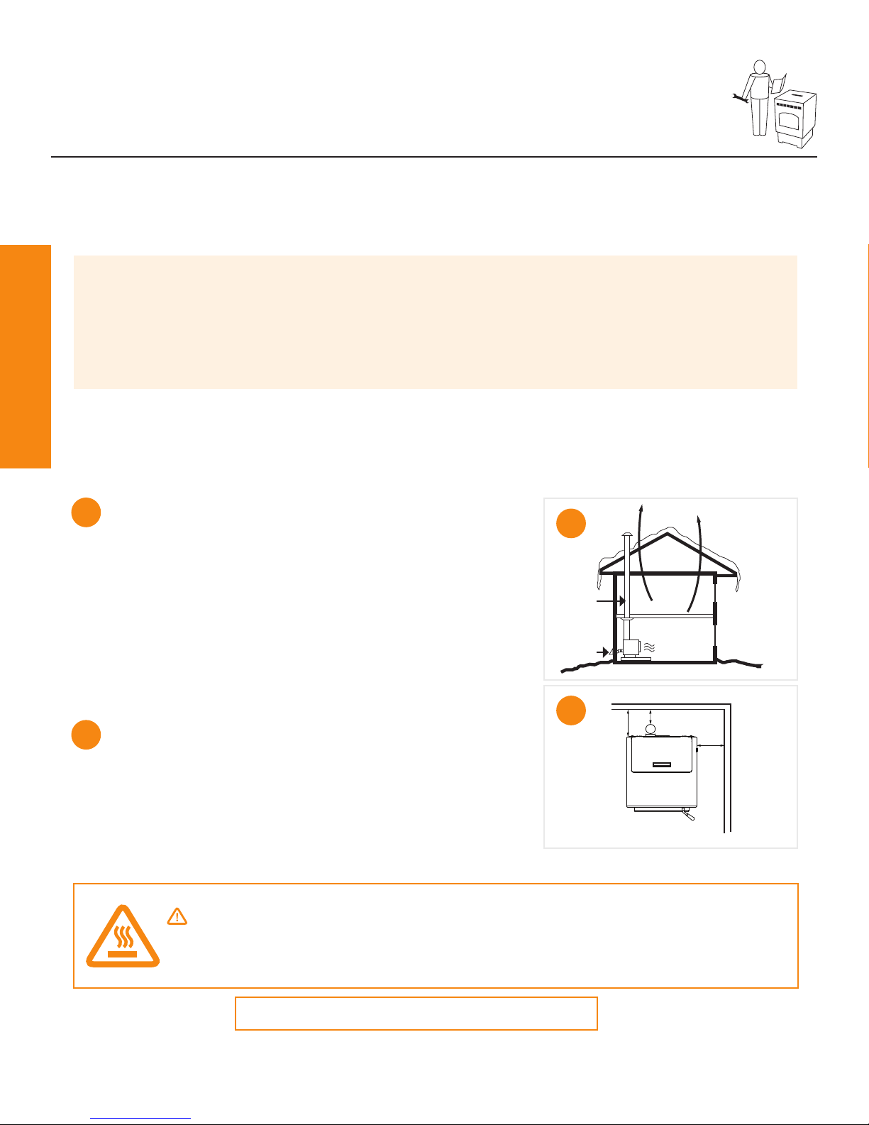
Installing Your Appliance.......................... 6
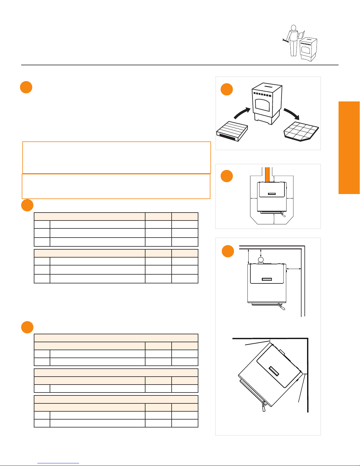
• Getting ready
• Placing your appliance
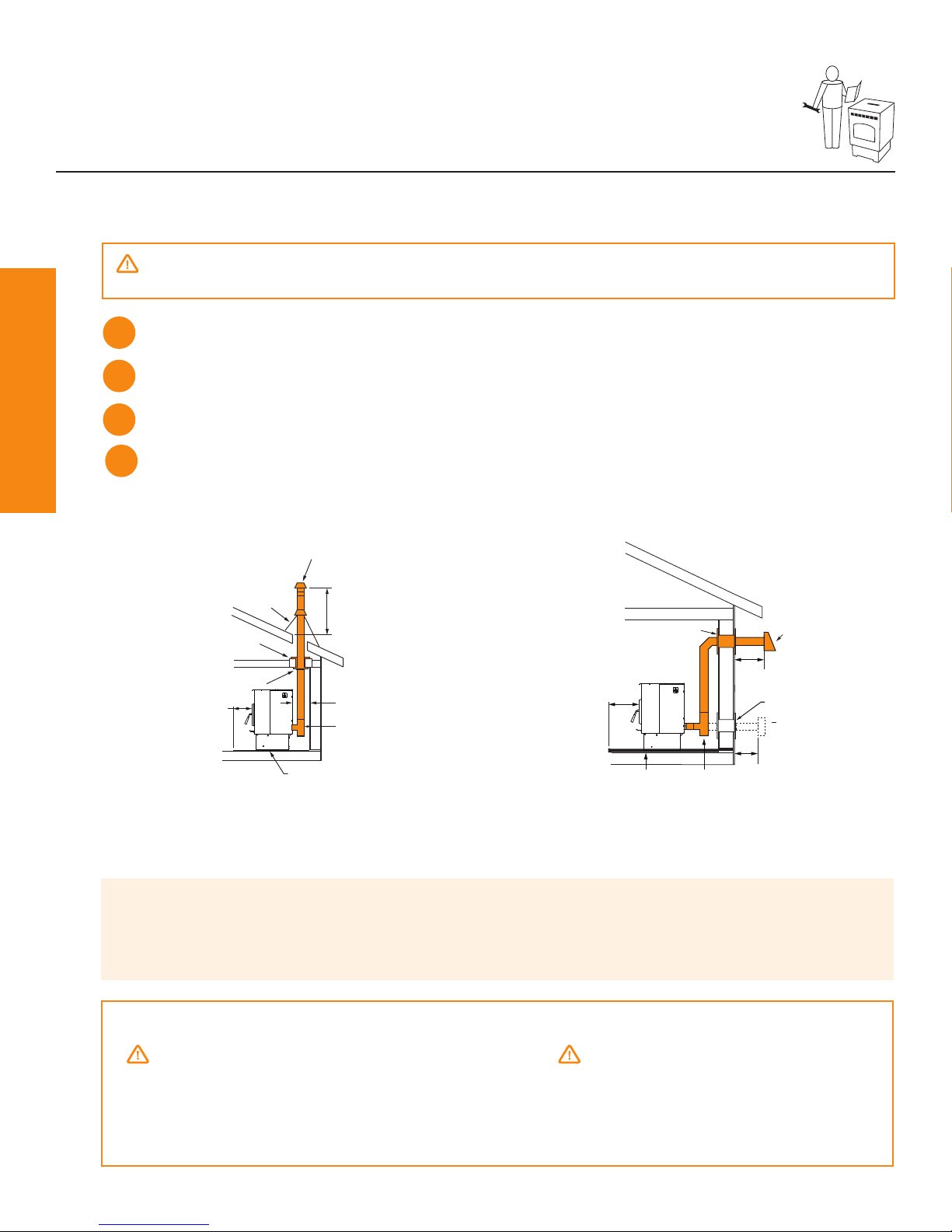
• Venting your appliance
Using Your Appliance.............................. 13
• Starting your appliance
• What to expect
• Comfort settings
• Turning your appliance off
Maintaining Your Appliance.................... 18
• What you may need
• Where, when and how
Troubleshooting ...................................... 22
• Power related
• Blockage related
Support..................................................... 27
• Contact information
• Ordering Parts
Listings and Certications ..................... 28
• Mobile home approval
• Glass specication
• Efciencies
• Appliance dimensions
• Warranty
PART NAME:
DRAWN BY: SCALE: MATERIAL:
UNLESS OTHERWISE SPECIFIED DIMS ARE INCHES[MM] & : TOLERANCESARE: (2) PLACE DEC : ± 0.03 (3) PLACE DEC: ± 0.005 ANGLE:± 2° FRACTION: ± 1/16
NORMAL DIM & INSIDE MATERIAL. OUTSIDE APEX INSIDE APEX - DIMS ENCLOSED BY AN OVAL ARE CRITICALDIMENSIONS
LABEL OPERATION AND MAINTENANCE
4. Suivez les instructions de démarrage.
Restablecer de error
1. Determinar el error de la tabla anterior.
2. Condición de error correcto. (consulte el Manual del Propietariopara
obtener información adicional.)
3. Gire el dial de control en la posición OFF,espere 10 segundos.
4. Siga las instrucciones de arranque.
Customer Service / Service Clients / Servicio al Cliente
www.pelprostoves.com
Vacuum / Vide / Vacío
CONFIDENTIALPROPERTY OF HEARTH & HOME TECHNOLOGIES INC.
PARTNAME:
DRAWNBY: SCALE: MATERIAL:
SHEET:
PARTNUMBER: REV:
THISPRINT IS CHECKED AND CONTROLLED BY THE ENGINEERING
DEPARTMENTSOF HEARTH & HOME TECHNOLOGIES INC.
LABEL CONTROL PANEL
MCW 1:1 SEE NOTE
1 OF 1
7083-167 B
UNLESS OTHERWISE SPECIFIED DIMS ARE INCHES[MM] & : TOLERANCESARE: (2) PLACE DEC : ± 0.03 (3) PLACE DEC: ± 0.005 ANGLE:± 2° FRACTION: ± 1/16
OUTSIDE MATERIAL.
74013 01/07/14 WPK
75292 06/05/14 MCW
1
2
3
Remove / Supprimer / Quitar
2. Deje enfriar la unidad antes de realizar cualquier trabajo de mantenimiento.
The appliance will automatically maintain the desiredcomfort level and shut down when level has
L'appareil passera automatiquement maintenir le niveau de confort désiré et arrêter lorsque le
Elaparato mantendrá automáticamente el nivel de confort deseado y se cerrará cuando el nivel se ha
** Theappliance will run continuously until switched to OFF or COMFORT LEVEL mode.
L'appareil fonctionne de façon continue jusqu'à ce que passe en mode OFF ou NIVEAU DE CONFORT.
El aparato funciona continuamentehasta que c ambia al modo OFF o NIVEL DE CONFORT.
A RELEASED
NOTE:
1. MATERIAL: NON-ANODIZED ALUMINUM 0.020 THICK
2. BACKGROUND: SILVER
3. COPY: BLACK
4. ADHESIVE: 3M #468 PERMANENT ACRYLIC
5. TEMPERATURE RATING: -50°F TO 350°F
B
CHG MIN/MAX TO HI/LO & AUTOMATIC TO COMFORT LEVEL.
ADD LOGO, UPDATE BACKGROUND COLORING
C BACKGROUND AND COPY NOTE UPDATD
D GROUPED LANGUAGES, REMOVED PHONE NUMBER
*
The appliance will automatically maintain the desiredcomfort level and shut down when level has
been achieved.
L'appareil passera automatiquement maintenir le niveau de confort désiré et arrêter lorsque le
niveau a été atteint.
Elaparato mantendrá automáticamente el nivel de confort deseado y se cerrará cuando el nivel se ha
logrado.
** Theappliance will run continuously until switched to OFF or COMFORT LEVEL mode.
L'appareil fonctionne de façon continue jusqu'à ce que passe en mode OFF ou NIVEAU DE CONFORT.
El aparato funciona continuamentehasta que c ambia al modo OFF o NIVEL DE CONFORT.
ECO# DATE BY
REV REVISIONS
A RELEASED 72901 06/19/13 MCW
B ADDEDWWW.PELPROSTOVES.COM 75290 06/05/14 MCW
NOTE:
1. MATERIAL: NON-ANODIZED ALUMINUM 0.020 THICK
2. BACKGROUND: SILVER
3. COPY: BLACK
4. ADHESIVE: 3M #468 PERMANENT ACRYLIC
5. TEMPERATURE RATING: -50°F TO 350°F
B
CHG MIN/MAX TO HI/LO & AUTOMATIC TO COMFORT LEVEL.
C BACKGROUND AND COPY NOTE UPDATD
D GROUPED LANGUAGES, REMOVED PHONE NUMBER
2. Deje enfriar la unidad antes de realizar cualquier trabajo de mantenimiento.
*
The appliance will automatically maintain the desired comfort level and shut downwhen level has
been achieved.
L'appareil passera automatiquement maintenir le niveau de confort désiré et arrêter lorsque le
niveau a été atteint.
Elaparato mantendrá automáticamente el nivel de confort deseado y se cerrará cuando el nivel se ha
logrado.
** The appliance will run continuously until switched to OFF or COMFORT LEVEL mode.
L'appareil fonctionne de façon continue jusqu'à ce que passe en mode OFF ou NIVEAU DE CONFORT.
El aparato funciona continuamente hasta que cambia al modo OFF o NIVEL DE CONFORT.
CONFIDENTIALPROPERTY OF HEARTH & HOME TECHNOLOGIES INC.
DRAWNBY: SCALE: MATERIAL:
SHEET:
PARTNUMBER: REV:
THISPRINT IS CHECKED AND CONTROLLED BY THE ENGINEERING
DEPARTMENTSOF HEARTH & HOME TECHNOLOGIES INC.
MCW 1:1 SEE NOTE
1 OF 1
7083-167 B
UNLESS OTHERWISE SPECIFIED DIMS ARE INCHES[MM] & : TOLERANCESARE: (2) PLACE DEC : ± 0.03 (3) PLACE DEC: ± 0.005 ANGLE: ± 2° FRACTION: ± 1/16
OUTSIDE MATERIAL. NORMAL DIM & INSIDE MATERIAL.
73351 9/3/2013 WPK
74013 01/07/14 WPK
75292 06/05/14 MCW
1
2
3
Remove / Supprimer / Quitar
2. Deje enfriar la unidad antes de realizar cualquier trabajo de mantenimiento.
The appliance will automatically maintainthe desired comfort level and shut down when level has
L'appareilpassera automatiquement maintenir le niveau de confort désiré et arrêter lorsque le
El aparato mantendrá automáticamente el nivel de confort deseado y se cerrarácuando el nivel se ha
** Theappliance will run continuously until switched to OFF or COMFORT LEVEL mode.
L'appareilfonctionne de façon continue jusqu'à ce que passe en mode OFF ou NIVEAU DE CONFORT.
El aparato funciona continuamentehasta que cambia al modo OFF o NIVEL DE CONFORT.
ECO# DATE BY
REV REVISIONS
A RELEASED 72901 06/19/13 MCW
B ADDED WWW.PELPROSTOVES.COM 75290 06/05/14 MCW
NOTE:
1. MATERIAL: NON-ANODIZED ALUMINUM 0.020 THICK
2. BACKGROUND: SILVER
3. COPY: BLACK
4. ADHESIVE: 3M #468 PERMANENT ACRYLIC
5. TEMPERATURE RATING: -50°F TO 350°F
C BACKGROUND AND COPY NOTE UPDATD
D GROUPED LANGUAGES, REMOVED PHONE NUMBER
1. Gire el dial de control en la posición OFF.
2. Deje enfriar la unidad antes de realizar cualquier trabajo de mantenimiento.
*
The appliance will automatically maintainthe desired comfort level and shut down when level has
been achieved.
L'appareilpassera automatiquement maintenir le niveau de confort désiré et arrêter lorsque le
niveau a été atteint.
El aparato mantendrá automáticamente el nivel de confort deseado y se cerrarácuando el nivel se ha
logrado.
** Theappliance will run continuously until switched to OFF or COMFORT LEVEL mode.
L'appareilfonctionne de façon continue jusqu'à ce que passe en mode OFF ou NIVEAU DE CONFORT.
El aparato funciona continuamentehasta que cambia al modo OFF o NIVEL DE CONFORT.

PelPro Cast Pellet Stove • 7083-171N • 9/8/17 pelprostoves.com4
Getting Started
WARNING!
Inspect appliance and components for damage.
Damaged parts may impair safe operation.
• Do NOT install damaged components.
• Do NOT install incomplete components.
• Do NOT install substitute components.
Report damaged parts to dealer.
Getting Started
Pallet Removal
There are bolts holding your PelPro appliance in
place on the pallet. To remove your appliance from
the pallet:
What’s Included
Pallet Removal
Visit pelprostoves.com
or scan the code:
1
Using a 5/16-inch
wrench, remove outside
brackets.
PP60 Pellet Stove
Owner’s Manual
Owner’s
manual
Door handle
Cleaning tool
Outside air kit
components:
Power cord
4” Flex hose Termination Cap Hose clamp Screws (4)
CAUTION!
Risk of cuts, abrasions or ying debris. Wear
protective gloves & safety glasses during install.
Metal edges are sharp.
Online Installation &
Trouble Shooting Videos

PelPro Cast Pellet Stove • 7083-171N • 9/8/17
pelprostoves.com 5
Getting Started
Getting Started
What You’ll Need
Tools & Supplies
• High temperature silicone
(500°F+)
• Level
• Phillips screwdriver
• Plumb line
• Tape measure
• Framing square
• Reciprocating saw
• Electric drill & bits
• Caulking gun
• Stud nder
• Utility knife
• Pliers
• Flashlight
• Hammer
Safety Equipment
Recommended for all installation and maintenance steps.
Pellet Vent Pipe
Must be an approved 3” or 4” diameter Type “L” or “PL” vent. Use 4” diameter vent if ue height
is over 15’ or if installation is over 3,000ft. above sea level.
Gloves Safety glasses Close-toed shoes
Floor Protection
Non-combustible material
(such as a hearth pad) is
required underneath your
appliance.
Surge Protector
Protect the electrical
components of your
appliance by using a surge
protector.
Pellet Fuel
Use only wood pellets
in your appliance. For
best performance, use
premium, low-ash pellets
(<1%) less than 1.5” in
length and avoid the dusty
bits and pieces of pellets
in the bottom of the bag.
WARNING!
Fire Risk. NO OTHER vent components may be used. Substitute or damaged vent components may
impair safe operation.

PelPro Cast Pellet Stove • 7083-171N • 9/8/17 pelprostoves.com6
Installing Your Stove
Installing Your Appliance
Your Home Acts Like a Chimney
We recommend that you help your home by:
1. Using a minimum of 5 feet of vertical venting
2. Use the supplied outside air kit
3. Install your appliance on a main oor location
This will:
• Help your appliance breathe
• Minimize smoke leakage in the house
• Enhance performance
Clearance to Combustibles
The space between your appliance and the items in
your home that could burn. Materials such as:
• Wood
• Sheet rock (drywall)
• Carpet
A
A
B
B
G
E
D
Getting Ready
1
23
WARNING!
Asphyxiation Risk.
DO NOT INSTALL IN A SLEEPING ROOM. Consumes oxygen in the room.
Pro Tip
We highly recommend your appliance and pellet vent pipe be installed by a professional installer.
Your retailer can make recommendations for you.
Installation MUST comply with local, regional, state and national codes and regulations.
Consult insurance carrier, local building inspector, re ofcials or authorities having jurisdic-
tion over restrictions, installation inspection and permits.
Placement
Where you place your appliance can signicantly affect its performance and safety.
For Canada, the installation must conform to CAN/CSA-B365

PelPro Cast Pellet Stove • 7083-171N • 9/8/17
pelprostoves.com 7
Installing Your Stove
Installing Your Appliance
Getting Ready (Continued)
Pellet Venting
Adding bends in the exhaust path restricts air ow,
reduces performance and provides a collection
point for ash deposits requiring more frequent
cleaning.
REQUIRED:
Use only 3” or 4” type “L” or “PL” pellet pipe.
C
C
CAUTION
• Do not connect to any air distribution duct or system
• Do not install a ue damper in the exhaust venting system of this
appliance
• Do not connect this appliance to a chimney ue serving another
appliance
• The structural integrity of the manufactured home oor, wall and
ceiling/roof must be maintained
Pro Tip
This appliance can be installed with a 3 to 6 inch (76-152mm) Top Vent Offset Adapter Kit. The
3 to 6 inch (76-152mm) Top Vent Offset Adapter are tested to use 24 gauge single wall ue
connector or Listed double wall ue connector to Class A Listed metal chimneys, or masonry
chimneys meeting International Conference of Building Ofcials (ICBO) standards for solid
fuel appliances.
Installation Video
Visit pelprostoves.com or scan this code:

PelPro Cast Pellet Stove • 7083-171N • 9/8/17 pelprostoves.com8
Installing Your Stove
Vent Termination Clearances
Installing Your Appliance
A
DB
L
C
K
J
B
I
H
G
F
Clearances
A 12” Clearance above grade, veranda porch, deck or balcony (Including vegetation and mulch)
B12” Clearance beside or below any windows or doors that open
12”* Clearance above any window or door that opens
C 18” Vertical clearance to ventilated soft located above the terminal within a horizontal distance of 2 feet from
the center line of the terminal
D 12” Clearance to an outside corner wall
F12”,
48” no outside air kit
Clearance to a non-mechanical air supply inlet to the building or a combustion air inlet to any other
appliance
G 36” Clearance to a mechanical air supply inlet
H 84”** Clearance above a paved sidewalk or paved driveway located on public property
I 12”** Clearance under a veranda, porch, deck or balcony
J 12” Clearance above the roof
K 24” Clearance from an adjacent wall including neighboring buildings
L
36” within a height of 15
feet above the meter /
regulator assembly
Clearance to each side of center line extended above natural gas or propane meter / regulator assembly
or mechanical vent
NOTICE:
Do NOT terminate vent:
• In any location that will allow ue gases or soot from
entering or staining the building
• In any location which could create a nuisance or hazard
• In any enclosed or semi-enclosed area such as a
carport, garage, attic, crawl space, under a sun deck or
porch or narrow walkway
• Closely fenced area, or any location that can build up
a concentration of fumes such as a stairwell, covered
breezeway, etc.
NOTICE:
Do NOT terminate below an air inlet.
• It is recommended that at least 60” (1.52m) of vertical
pipe be installed when appliance is vented directly
through a wall—this will create a natural draft, which
will help prevent the possibility of smoke or odor
venting into the home during a power outage
• It will also keep exhaust from causing a nuisance
or hazard by exposing people or shrubs to high
temperatures
• The safest and preferred venting method is to extend
the vent vertically through the roof or above the roof
*Recommended to prevent condensation on windows and thermal breakage. **This is a recommended distance. For additional requirements check local codes.

PelPro Cast Pellet Stove • 7083-171N • 9/8/17
pelprostoves.com 9
Installing Your Stove
Installing Your Appliance
1
2
1
2
3
Notice: Be careful to protect the bottom of the appliance
and oor surfaces when moving the appliance. Bottom
edges of appliance are sharp and can scratch surfaces.
Notice: Clearances may only be reduced by means
approved by the regulatory authority having jurisdiction.
Conrm required clearances to combustibles:
3
Vertical Installations (Interior Flue)
Straight back against wall Inches mm
D Back wall to pellet pipe 3 254
E Side wall to appliance 13 330
USA Hearth Pad Requirements Inches mm
A Sides 2 51
B Back 2 51
C Front 6 152
Horizontal Installations
Straight back against wall Inches mm
G Back wall to appliance 2 51
E Side wall to appliance 13 330
Corner Installation
Straight back against wall Inches mm
F Walls to appliance 3 76
Non-combustible oor protection extending beneath the ue pipe is required
with horizontal venting or under the top vent adapter with vertical installation.
*Non-combustible oor protection must extend 2 inches (51mm) beneath the
ue pipe when installed horizontal venting or under the top vent adapter with
vertical installation. CANADA REQUIRED, USA RECOMMENDED.
Canada Hearth Pad Requirements Inches mm
A Sides 8 203
B Back 2 51
C Front 6 152
Hearth pad minimum requirements:
B*
A
C
A
F
F
G
E
D
Placing Your Appliance
It is necessary to install EMBER PROTECTION; a Type
I oor protector for this appliance.
The Floor protector must be non-combustible material, extend-
ing beneath appliance
with a minimum of 6
inches (152mm) in
front of glass and 6 inches (152mm) to both sides of the fuel
loading door. Open the door and measure 6 inches (152mm)
from the side edge of the opening in the face of the appliance.

PelPro Cast Pellet Stove • 7083-171N • 9/8/17 pelprostoves.com10
Installing Your Stove
Installing Your Appliance
Vertical - Interior, Preferred Installation Exterior - Optional Installations
Install venting. (For additional installation options visit pelprostoves.com)
3
Install wall thimble (sold separately) per manufacturer requirements.
2
Venting Your Appliance
CAUTION!
Take appropriate precautions to locate utilities within the wall and avoid contact.
Use silicone to create an effective vapor barrier at the location where the chimney or
other component penetrates to the exterior of the structure.
4
Mark and cut wall for venting penetration on exterior wall (if needed).
1
Pro Tips
• See venting manufacturer’s required clearances to combustibles
• For horizontal installations, the minimum clearance from exterior to termination cap is 6”—you
may want to increase to 18” clearance to minimize soot blow back on home exterior.
WARNING!
Do not terminate venting in any enclosed or semi-enclosed area
such as: a carport, garage, attic, crawl space, under a sun deck
or porch, narrow walkway or closely fenced area, or any location
that can build up a concentration of fumes such as a stairwell,
covered breezeway, etc.
CAUTION!
Ensure that your appliance venting terminates
above your appliance. The following may occur:
• Your appliance appliance will not draft properly
• Smoke may seep in your house
• Excessive sooting
Install vent at clearances specied by the manufacturer
NOTE: In Canada when using a factory-built chimney it must be safety listed, Type UL103 HT (2100
o
F) CLASS “A” or
conforming to CAN/ULC-S629M, STANDARD FOR 650oC FACTORY-BUILT CHIMNEYS.
6 in.
(152mm)
Min.
Clean-out T
Firestop
Flashing
Rain Cap
Non-combustible Hearth Pad
12 in. (305mm) Minimum
Ceiling Support
Follow pipe manufacture
listed clearance
RELEASED
ITEM PART NUMBER
- ---- -----
11.75
11.75
RELEASED
RELEASED
Non-combustible
Hearth Pad
Wall Thimble
Horizontal
Termination Cap
Termination
Cap
6 in. (152 mm)
Minimum
6 in.
(152 mm)
Minimum
Clean Out T
Wall Thimble
6 in.
(152 mm)
Minimum

PelPro Cast Pellet Stove • 7083-171N • 9/8/17
pelprostoves.com 11
Installing Your Stove
• 45° elbow is equivalent to 1 foot of straight pipe
• 90° elbow is equivalent to 3 feet of straight pipe
Installing Your Appliance
Notice:
These are guidelines for successful venting of
your pellet appliance. The more vertical rise
you can obtain in your system, the better it will
perform. Horizontal vent runs can accumulate
ash and will need to be cleaned more often.
Try to keep them as short as possible.
Venting Your Appliance
The maximum horizontal venting allowed with no vertical
venting attached is 48 inches including one 90° elbow
or two 45° elbows. Addition of any horizontal venting
beyond 48 inches requires a minimum 60 inches of
additional vertical vent. Horizontal sections of vent pipe
should have a 1/4 inch rise per foot. We recommend
using the shortest venting and fewest elbows possible
when venting horizontal.
We recommend the use of 4 inch vent with any
installation requiring more than two 90° elbows, or more
than 15 feet of venting.
WARNING!
Fire Risk.
• Only LISTED venting
components may be
used
• NO OTHER vent components may be used.
Substitute or damaged vent components
may impair safe operation.
Minimum Vertical Vent for One Elbow
0
5
10
15
20
0510 15 20
Horizontal Run, (ft)
Minimum Vertical Rise
(ft)
Horizontal Run (FT)
Minimum Vertical Vent for One Elbow
Minimum Vertical Vent for Three Elbows
0
5
10
15
20
25
024681012
Length of Horizontal Sections (ft)
Minimum Vertical Rise
(ft)
Minimum Vertical Vent for Three Elbows
Length of Horizontal Sections (FT)
Minimum Vertical Vent for Two Elbows
0
5
10
15
20
0510 15
Length of Horizontal Sections, (ft)
Minimum Vertical
Rise, (ft)
Minimum Vertical Vent for Two Elbows
Length of Horizontal Sections (FT)
ONE 90° ELBOW
Total
Horizontal
Minimum
Vertical
Vent
Diameter
403
553
663
773
884
994
10 10 4
11 11 4
12 12 4
13 13 4
14 14 4
15 15 4
16 16 4
17 17 4
18 18 4
19 19 4
TWO 90° ELBOWS
Total
Horizontal
Minimum
Vertical
Vent
Diameter
253
363
473
583
693
7104
8114
9124
10 13 4
11 14 4
12 15 4
13 16 4
14 17 4
15 18 4
THREE 90° ELBOWS
Total
Horizontal
Minimum
Vertical
Vent
Diameter
2114
3124
4134
5144
6154
7164
8174
9184
10 19 4
11 20 4
Minimum Vertical Vent for One Elbow
0
5
10
15
20
0510 15 20
Horizontal Run, (ft)
Minimum Vertical Rise
(ft)
Horizontal Run (FT)
Minimum Vertical Vent for One Elbow
Minimum Vertical Vent for Three Elbows
0
5
10
15
20
25
024681
01
2
Length of Horizontal Sections (ft)
Minimum Vertical Rise
(ft)
Minimum Vertical Vent for Three Elbows
Length of Horizontal Sections (FT)
Minimum Vertical Vent for Two Elbows
0
5
10
15
20
0510 15
Length of Horizontal Sections, (ft)
Minimum Vertical
Rise, (ft)
Minimum Vertical Vent for Two Elbows
Length of Horizontal Sections (FT)
ONE 90° ELBOW
Total
Horizontal
Minimum
Vertical
Vent
Diameter
403
553
663
773
884
994
10 10 4
11 11 4
12 12 4
13 13 4
14 14 4
15 15 4
16 16 4
17 17 4
18 18 4
19 19 4
TWO 90° ELBOWS
Total
Horizontal
Minimum
Vertical
Vent
Diameter
253
363
473
583
693
7104
8114
9124
10 13 4
11 14 4
12 15 4
13 16 4
14 17 4
15 18 4
THREE 90° ELBOWS
Total
Horizontal
Minimum
Vertical
Vent
Diameter
2114
3124
4134
5144
6154
7164
8174
9184
10 19 4
11 20 4
One 90° Elbow
Total
Horizontal
Minimum
Vertical
Vent
Diameter
403
553
663
773
884
994
10 10 4
11 11 4
12 12 4
13 13 4
14 14 4
15 15 4
16 16 4
17 17 4
18 18 4
19 19 4
Two 90° Elbows
Total
Horizontal
Minimum
Vertical
Vent
Diameter
253
363
473
583
693
710 4
811 4
9 12 4
10 13 4
11 14 4
12 15 4
13 16 4
14 17 4
15 18 4
Three 90° Elbows
Total
Horizontal
Minimum
Vertical
Vent
Diameter
211 4
3 12 4
4 13 4
5 14 4
6 15 4
7 16 4
8 17 4
9 18 4
10 19 4
11 20 4

PelPro Cast Pellet Stove • 7083-171N • 9/8/17 pelprostoves.com12
Installing Your Stove
Installing Your Appliance
Pro Tip
Installing a clean-out “T” (sold separately) to the rear
of your appliance, when venting vertically can save time during cleaning.
Install outside air kit (included)
For optimal performance, PelPro recommends the
outside air kit for all installations. Outside air kit is
required for all mobile/manufactured home installations.
Install through wall B
• Maintain clearances from exhaust
• Remove knock out in the rear of appliance
- Attach ex pipe to outside air connection
on appliance
- Use hose clamp
- Route tube outside the structure
- Attach cap
- Secure to outside wall with appropriate fasteners
Take a Break
Inspect your work:
_____ Conrm clearances to combustibles are maintained
_____ Pipe joints are secure and properly sealed
_____ Outside air kit installed properly
_____ Conrm termination clearances
6B
CAUTION!
Never draw outside
combustion air from:
• Wall, oor or ceiling cavity
• Enclosed space such as an
attic, garage or crawl space.
• Install pellet venting through wall and connect vent/pipe to
appliance A
• Some venting manufacturers offer pellet appliance
adapters for their venting for easier installation
• Seal all pipe joints using high-temp silicone (500°+)
• Secure exhaust venting system to the appliance with at
least 3 screws or rivets per the pipe manufacturer’s instruc-
tions. Also secure all connector pipe joints with at least 3
screws through each joint.
• Install termination cap
• Conrm all required appliance clearances to combustibles
A5

PelPro Cast Pellet Stove • 7083-171N • 9/8/17
pelprostoves.com 13
Using Your Stove
Using Your Appliance
Fuel Material and Fuel Storage
Pellet fuel quality can greatly uctuate. We recommend that you buy fuel in multi-ton lots
whenever possible. However, we do recommend trying various brands before purchasing
multi-ton lots to ensure your satisfaction. Store fuel in dry location not within clearances to
combustibles of your appliance.
Fuel Material
• Made from sawdust or wood by-products
• Depending on the source material it may have a high or low ash content.
Higher Ash Content Material
• Hardwoods with a high mineral content
• Fuel that contains bark
• Standard grade pellets or high ash pellets
Lower Ash Content Material
• Most softwoods
• Fuels with low mineral content
• Most premium grade pellets
Fuel Tips
Pro Tip
We recommend the use of Pellet Fuels Institute certied pellet fuel with this product.
Your appliance has a manufacture-set minimum low burn rate that must not be altered. It is
against federal regulations to alter this setting or otherwise operate your appliance in a man-
ner inconsistent with operation instructions in this manual.

PelPro Cast Pellet Stove • 7083-171N • 9/8/17 pelprostoves.com14
Using Your Stove
Using Your Appliance
WARNING!
HOT SURFACES! Glass and other surfaces are hot during operation AND cool down.
Hot glass will cause burns.
• Do not touch glass until it is cooled
• NEVER allow children to touch glass
• Keep children away
• CAREFULLY SUPERVISE children in same room as replace
• Alert children and adults to hazards of high temperatures
• High temperatures may ignite clothing or other ammable materials
• Keep clothing, furniture, draperies and other ammable materials away
What to Expect
1Combustion blower will turn on
2Igniter will turn on
3 Pellets will drop, smoke may occur in rebox but will
evacuate, and ame will appear in re pot.
4Convection blower will automatically turn on after the
appliance heats up. Convection blower will continue
to run even after your appliance has been shut
down.
Pro Tips
• Odors and vapors are released during initial startup after purchase; burning your appliance
on HI for 30 minutes will allow the paint to cure. Open windows or doors for air circulation
until burn off is complete.
• During start up and normal operation your appliance’s front door must be closed
• Priming is only required the rst time your appliance is lit, or after a FUEL FEED ALARM.
Starting your appliance the rst time
WARNING!
Fire Risk
Keep combustible materials, gasoline and other ammable vapors and liquids clear of appliance.
• Do NOT operate appliance with door open
• Do NOT operate appliance with re pot oor open
• Do NOT store ammable materials in the appliance’s vicinity
• Do NOT use gasoline, lantern fuel, kerosene, charcoal lighter uid or similar liquids or gels to start or
“freshen up” a re in this appliance
Keep all such liquids well away from the appliance while it is in use as combustible materials may ignite.
1
2
4
3

PelPro Cast Pellet Stove • 7083-171N • 9/8/17
pelprostoves.com 15
Using Your Stove
FRONT
Important:
Allow up to 20 minutes for
your appliance to start.
1
Use and Care
Visit pelprostoves.com or scan this code:
1
WARNING! Shock hazard.
• Plug directly into properly grounded 3 prong receptacle
• Do NOT route cord under or in front of appliance
• Recommend the use of a surge protector
33
1122
4
2
2
3
3
Conrm three bafes inside rebox are secure,
placing the side bafes before the center
Add some pellets to hopper and fully close lid
Conrm re pot is properly positioned
Using Your Appliance
2
1
4
3
56
7
8
9
10
LO
OFFHI
0
-
1
-
2
-
3
-
4
+
1
+
2
+
3
+
4
O
N
A
U
T
O
A
L
A
R
M
2
1
4
3
56
7
8
9
10
LO
OFF HI
4
Ensure dial control is set in off position.

PelPro Cast Pellet Stove • 7083-171N • 9/8/17 pelprostoves.com16
Using Your Stove
Starting your appliance from an empty hopper
6
CAUTION:
During this process DO NOT:
• Try to restart, manually add pellets or use any type of accelerant
Using Your Appliance
Wait 1 minute - LED light will start ashing green once per second.
2
1
4
3
56
7
8
9
10
LO
OFFHI
0
-
1
-
2
-
3
-
4
+
1
+
2
+
3
+
4
O
N
A
U
T
O
A
L
A
R
M
2
1
4
3
56
7
8
9
10
LO
OFF HI
6
2
1
4
3
56
7
8
9
10
LO
OFFHI
2
1
4
3
56
7
8
9
10
LO
OFF HI
12
3
7
7Prime your appliance:
1) Quickly turn the dial control from OFF to HI
2) Back to OFF
3) Then back to HI
The feed motor will run continuously for two minutes and the LED light will be solid green.
Once primed, pellets will drop into the re pot and the LED light will blink green as ignition
starts. This process can take up to 20 minutes.
Plug in your appliance
55

PelPro Cast Pellet Stove • 7083-171N • 9/8/17
pelprostoves.com 17
Using Your Stove
Using Your Appliance
What Do the Blinking Lights Mean?
Green & Amber - Normal Operation
• Green, Steady On - Feed system is priming
• Green, 1 Blink - Appliance is off and ready
• Green, Continuous Blinking - Appliance is in the start up/ignition sequence
• Green, Varies Blinks - Varies depending on burn rate
• Amber, Steady On - Appliance is set and running at either the minimum or maximum power
levels
• Amber, Continuous Blinking - Appliance is in the shutdown sequence. *Early models may have
a green continuous blinking light during shutdown sequence.
Red - Operational Issue - Refer to troubleshooting
• Red, 1 Blink - Empty hopper, refer to troubleshooting
• Red, 2 Blinks - Exhaust probe alarm, check connections or refer to troubleshooting
• Red, 3 Blinks - Ambient probe alarm, check connections or refer to troubleshooting
• Red, 4 Blinks - Missed ignition, refer to troubleshooting
• Red, 8 Blinks - Exhaust gas over temperature, refer to troubleshooting
If your appliance does not ignite on the initial burn,
the LED light will blink red 4 times indicating a missed
ignition.
1. Turn your appliance to off, remove and clean
the re pot
2. Conrm re pot is properly positioned
3. Prime your appliance per previous instructions
2
1
4
3
56
7
8
9
10
LO
OFFHI
0
-
1
-
2
-
3
-
4
+
1
+
2
+
3
+
4
O
N
A
U
T
O
A
L
A
R
M
2
1
4
3
56
7
8
9
10
LO
OFF HI
Is this your rst start-up after purchase?
If you just bought this appliance, once a re has been established in your appliance,
leave the appliance burning on HI for 30 minutes to allow paint to cure.
After 30 minutes, turn the dial control to OFF and allow your appliance to cool
completely. Once cooled, clean the re pot. Your appliance is now ready to resume
normal use.

PelPro Cast Pellet Stove • 7083-171N • 9/8/17 pelprostoves.com18
Using Your Stove
Using Your Appliance
Comfort Settings
Control your comfort with a single dial:
• OFF setting - Used to turn your appliance off
• LO setting – Your appliance will continue to run on low
regardless of room temperature. LED light will be steady
amber
• 1 through 10 settings – Set to your desired comfort
level. Once the desired comfort level is achieved the
appliance will automatically shut down. When the
temperature in the room drops below the desired
comfort level, your appliance will automatically restart.
2
1
4
3
56
7
8
9
10
LO
OFFHI
0
-
1
-
2
-
3
-
4
+
1
+
2
+
3
+
4
O
N
A
U
T
O
A
L
A
R
M
2
1
4
3
56
7
8
9
10
LO
OFF HI
Pro Tip
If the dial control is turned to the off position and then back on, even if by mistake,
your appliance will go through the shutdown process (approximately 15 minutes) and
restart.
Thermostat
Your PelPro appliance comes with a built-in thermostat system that provides easy
temperature adjustments. The appliance is not designed to use a remote control or
external thermostat.
Trim
Adjustment
• HI setting - Your appliance will continue to run on high regardless of room temperature. LED light
will be steady amber.
Trim Adjustment
Trim adjustment is the small dial located below the main dial control. Rotating this dial will adjust the
air/fuel ratio and below are examples of when to use it:
• If the re is too large, lazy or producing black soot, rotate the dial counterclockwise one level at a
time and allow 15 minutes for stabilization before making another adjustment
• If your re is too small and sometimes goes out when there are pellets in the hopper, rotate the
dial clockwise one level at a time and allow 15 minutes for stabilization before making another
adjustment.

PelPro Cast Pellet Stove • 7083-171N • 9/8/17
pelprostoves.com 19
Using Your Stove
Using Your Appliance
2
1
4
3
56
7
8
9
10
LO
OFFHI
0
-
1
-
2
-
3
-
4
+
1
+
2
+
3
+
4
O
N
A
U
T
O
A
L
A
R
M
2
1
4
3
56
7
8
9
10
LO
OFF HI
2
1
4
3
56
7
8
9
10
LO
OFFHI
0
-
1
-
2
-
3
-
4
+
1
+
2
+
3
+
4
O
N
A
U
T
O
A
L
A
R
M
2
1
4
3
56
7
8
9
10
LO
OFF HI
2
1
4
3
56
7
8
9
10
LO
OFFHI
0
-
1
-
2
-
3
-
4
+
1
+
2
+
3
+
4
O
N
A
U
T
O
A
L
A
R
M
2
1
4
3
56
7
8
9
10
LO
OFF HI
95102,32yraurbeF•H171-3807moc.sevotsorplep.www
1 32
5
4
Turn dial to OFF
position
Auger stops feeding
pellets
LED light will ash
amber rapidly *Early
models may have
a green continuous
blinking light during
shutdown sequence.
LED light will ash
once per second
Blowers continue
to run until after the
exhaust temperature
has cooled
Turning Your Appliance Off
CAUTION!
Smoke Hazard
• Turn dial control to OFF, let appliance completely cool and exhaust blower
must be off. Now you can unplug appliance before servicing
• Smoke spillage into room can occur if appliance is not cool before unplugging

PelPro Cast Pellet Stove • 7083-171N • 9/8/17 pelprostoves.com20
Maintaining Your Stove
ECO# DATE BY
REV REVISIONS
A RELEASED 72901 06/19/13 MCW
B ADDED WWW.PELPROSTOVES.COM 75290 06/05/14 MCW
NOTE:
1. MATERIAL: NON-ANODIZED ALUMINUM 0.020 THICK
2. BACKGROUND: SILVER
3. COPY: BLACK
4. ADHESIVE: 3M #468 PERMANENT ACRYLIC
5. TEMPERATURE RATING: -50°F TO 350°F
B
CHG MIN/MAX TO HI/LO & AUTOMATIC TO COMFORT LEVEL.
C BACKGROUND AND COPY NOTE UPDATD
D GROUPED LANGUAGES, REMOVED PHONE NUMBER
2. Deje enfriar la unidad antes de realizar cualquier trabajo de mantenimiento.
*
The appliance will automatically maintain the desired comfort level and shut downwhen level has
been achieved.
L'appareilpassera automatiquement maintenir le niveau de confort désiré et arrêter lorsque le
niveau a été atteint.
El aparato mantendrá automáticamente el nivel de confort deseado y se cerrarácuando el nivel se ha
logrado.
** The appliance will run continuously until switched to OFF or COMFORT LEVEL mode.
L'appareilfonctionne de façon continue jusqu'à ce que passe en mode OFF ou NIVEAU DE CONFORT.
El aparato funciona continuamente hasta que cambia al modo OFF o NIVEL DE CONFORT.
Maintaining Your
Appliance
What You’ll Need
Metal container
with lid
Flue cleaning
brush
Ceramic glass cleaner &
non-abrasive cloth
Ash vacuumDrop cloth
Gloves
Safety glassesCleaning tool
Cleaning & Maintenance
Important:
Regular cleaning helps to assure optimal performance of your appliance. Please refer to
page 29 to log your maintenance and cleaning.
Cleaning your
appliance
Visit pelprostoves.com or
scan this code:
Phillips head
screwdriver
Maintaining your
appliance
Visit pelprostoves.com or
scan this code:
Other manuals for PP60
4
Table of contents
Other Pelpro Pellet Stove manuals

Pelpro
Pelpro Freestanding User manual

Pelpro
Pelpro PP60 User manual

Pelpro
Pelpro FPP Step Top Freestanding User manual

Pelpro
Pelpro HHPP2 User manual

Pelpro
Pelpro PP60 User manual

Pelpro
Pelpro FPP User manual

Pelpro
Pelpro PP60 Manual

Pelpro
Pelpro PP130 User manual

Pelpro
Pelpro PP130 User manual

Pelpro
Pelpro PP130-B User manual
Popular Pellet Stove manuals by other brands

Even Embers
Even Embers HTR1085AS owner's manual

Quadra-Fire
Quadra-Fire SANTAFE-MBK owner's manual

HAMPTON BAY
HAMPTON BAY GCI60 owner's manual

Haas+Sohn
Haas+Sohn HSP 4.0-F2 Installation and operating manual

Horus
Horus AQUA 14.0 Operating, installation and maintenance manual

MCZ
MCZ CLUB operating & maintenance manual