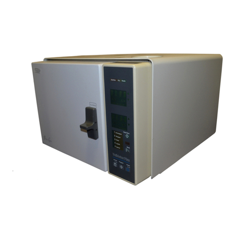
Pelton & Crane Solaris 2 SSC Series User manual

Solaris 2
Sterilizaton Center
Installation Manual
Model: SSC
8’ - SSC96-2-R
8’ - SSC96-2-L
10’ - SSC120-2-R
10’ - SSC120-2-L
achRules!
12’ - SSC147-2-R
12’ - SSC147-2-L

Phone: 800-659-5922
Fax: 800-659-7255
Technical assistance is available Monday through Friday, 8:00
am to 6:00 P.M. (Eastern Standard Time).
Technical Support
TABLE OF CONTENTS
GENERAL INFORMATION ........................................................................................................................................................................................3
PRODUCT IDENTIFICATION ....................................................................................................................................................................................4
PREPARING THE SITE .............................................................................................................................................................................................5
CABINET BASE INSTALLATION...............................................................................................................................................................................8
BACK PANELS TO CABINET INSTALLATION ..........................................................................................................................................................9
HANGING RAIL INSTALLATION...............................................................................................................................................................................13
ELECTRICAL STRIP INSTALLATIO
N.......................................................................................................................................................................15
UPPER STORAGE INSTALLATION.........................................................................................................................................................................14
THREE SHELF STERILIZATION TOWER INSTALLATION.....................................................................................................................................12
GENERAL ROUTING GUIDE....................................................................................................................................................................................16
PLUMBING SCHEMATIC..........................................................................................................................................................................................18
LIGHT, ELECTRICAL, & PNEUMATIC DOOR CONTROLS.....................................................................................................................................19
ELECTRICAL STRIPS AND STERILIZER TOWER ELECTRICAL SCHEMATIC.....................................................................................................20
FINAL ASSEMBLY/ADJUSTMENT.............................................................................................................................................................................21
ZachRules!
TOWER INSTALLATION..........................................................................................................................................................................................10
VISTAPURETM INSTALLATION................................................................................................................................................................................17

3
Model Designation: Solaris Sterilization Center Cabinet
Power Supply: SSC-120V/230V~50-60Hz,
15A Service (For each circuit)
Protection against harmful ingress penetration of water:
Ordinary Equipment
Technical Description
GENERAL INFORMATION
Definition of Symbols
WARNING: Only authorized service
technicians should attempt
to service this equipment.
Use of other than authorized
technicians will void the
warranty.
WARNING: This product must be
disinfected before use.
This product is intended for use by trained
dental/medical professionals only.
The following symbols may be used throughout
this manual:
Risk of electrical shockpresent.
Make sure power is disconnected before
attempting this procedure.
WARNING: Failure to carefully follow the
described procedure may result in damage
to the equipment and/or injury to the patient/
operator.
See operating instructions.
(AC) Alternating current.
Protective earth (Ground)
Manufacturing Date
Waste Electrical and Electronic Equipment.
Type B Applied part.
Indicates conformity to General Requirements for
Safety is certified by Intertek Testing Services.
General mandatory action required, important to
follow instruction. Not a caution.
Warning, strong magnetic field.
Off
On
Light Switch
Mode of operation: SSC-Continuous
Interference with Electromedical Devices
To guarantee the safety of electromedical devices, it
is recommended that the operation of mobile radio
telephones in the medical practice or hospital be
prohibited.
Strong EMI sources such as electro-surgery units or
x-ray units may affect performance. If performance
issues occur, move the unit to another electrical
circuit or physical location.
Product Disposal
Contact your local authorized dealer for proper
disposal of the device to ensure compliance with
your local environmental regulations.
Incompatible Units or Accessories
To guarantee the operational safety and function
of this device, the use of unapproved units or
accessories is not advised. Doing so could
result in potential hazard. Only use Pelton &
Crane approved accessories and devices.
1.013.2466 R00
Product Identification
This cabinet can be identified by its product
label, located inside the cabinet beneath the sink
on the left wall. This label states the cabinet model
and serial number, electrical specifications,
manufacture date and safety classification. Note the
SAMPLE label shown below.
ZachRules!
Manufacturing Place
34488
DENTAL ___ __VAC__A__HZ
ETL CLASSIFIED

4
PRODUCT IDENTIFICATION
1.013.2466 R00

5
Front View
PREPARING THE SITE
Side View
1.013.2466 R00
ZachRules!

6
NOTE:
Select the location for the cabinet that will meet the operator’s arm reach and storage requirements. Refer to
the dimensional drawings while considering the location of air, water and electrical connections.
NOTE:
Wall Stub-Out Specifications
Air & Water Shut-off Valves :
1/2" pipe N.P.T. (supplied by the contractor) protruding 1" from floor or wall.
Manual shut-off valve supplied by the dealer to be installed by the contractor. Maximum height can not
exceed 4" when valves are fully opened.
- Air pressure should be set at
70-80 PSIG
.
- Water pressure should be set at
35-40 PSIG
.
Central Vacuum:
5/8" OD tube protruding 1” from floor/wall.
Drain
: 1-1/2” OD tubing protruding 1" from floor/wall.
Wall Stub-Out Locations
NOTE:
PREPARING THE SITE
1.013.2466 R00
Always lift cabinets by bottom edge, being careful to lift with your legs and not your
back.
Make all required air, water, and drain attachments from the utilities to the incoming
stub-up connections before the system installation occurs. Doing so prevents damage
to the utility lines from heat associated with some plumbing connection methods.
To ensure proper operation of the unit, flush air and water lines before connecting the
equipment.
Turn main power OFF at the installation site.
When installing the sterilization center, ensure it is bolted in place when installed
according to the instructions provided.
Use template to locate utilities in relation to operator’s reach. Because of varying city plumbing
and electrical codes, the dealer should ensure that installation meets local requirements. Pelton
& Crane cannot be responsible for an installation which does not meet local plumbing and electrical
codes
It is recommended to remove base boards on the back and/or side walls so that the cabinet will
be flush to the wall or mounted on a flat finish wall.
WARNING:
WARNING:
WARNING:
WARNING:

7
ELECTRICAL SPECIFICATIONS
Depending on the options ordered, the cabinet should be permanently connected to up to 9 individual
branch circuits.
The GFCI electrical chase located in the receiving /cleaning and
prep
& pack areas should be permanently
connected to 120vac15amp circuits.
The electrical box located in the sterilization tower contains two (2) 120vac, 15amp branch circuits or
two (2) 230vac, 15amp branch circuits. If there is a three shelf tower being installed, there will be
Consult local electrical code for proper method in your area.
GROUNDING INSTRUCTIONS: THIS CABINET MUST BE CONNECTED TO A GROUNDED METAL,
PERMANENT WIRING SYSTEM, OR AN EQUIPMENT GROUNDING CONDUCTOR MUST BE RUN
WITH THE CIRCUIT CONDUCTORS AND CONNECTED TO THE GROUNDING LEAD ON EACH
CIRCUIT.
DC2 - Light control box: 120VAC, 50/60 hz, 15A
DC1 - Receiving/Cleaning Receptacles 120VAC, 50/60hz, 15A
DC4 - Pack/Prep Receptacles 120VAC, 50/60hz, 15A
DC5-8 - Sterilization Tower Receptacle 120VAC, 50/60hz, 15A
Bottom-Sterilization Tower Receptacle 120VAC, 50/60hz, 15A (2 circuits)
or Sterilization Tower Receptacle 230VAC, 50/60hz, 15A (2 circuits)
An additional 2 circuit Sterilization Tower Receptacle is supplied for 3 shelf towers.
four (4) 120VAC, 15 amp branch circuits or four (4) 230VAC, 15 amp circuits.)
Typical Individual Circuits
PREPARING THE SITE
The Receiving/Cleaning Receptacles, Pack/Prep Receptacles, and the Sterilization Tower Receptacles
have individual armored cable pigtails that are supplied to permanently connect them to the building’s wiring system
as individual circuits. Depending on configuration of the Solaris Cabinet, the number of pigtails may vary.
NOTE: All wiring must be installed in accordance with local codes. To avoid risk of electric shock, this equipment
must be wired only to supply mains with protective earth connections.
1.013.2466 R00
ZachRules!
DC2 - Sensomatic waste drawer: 100-240VAC, 50/60hz, 2A
DC2 - Faucet sensor: 120VAC, 50/60hz, 15A
DC3 - Air HVE switch: 300VAC, 50/60hz, 15A

8
1. Remove sink base module, and partitions from their
packaging. remove hardware
2. Remove doors and drawers from cabinets taking care to
store doors in a manner in which all can go back in their
original positions. The hinges installed are snap-on/off and
can easily be removed by pulling the tab marked "pull" lo-
cated at the back end of the hinge base plate. Hold door
securely when disengaging from the hinge. The door will
come loose quickly when the tab is pulled.
Note: False floors are located inside some of the base
cabinets. These false floors can be removed as the in-
dividual bases are installed.
NOTE: These installation instructions describe the procedures with the technician facing the front of the
cabinet.
Pull
Tab
WARNING: Be sure the main power is turned
off at the installation site.
WARNING: Do not lift cabinets by their
countertops.
3. Remove false floors from the lower modules..
4. Position sink cabinet base over the sink plumbing stub ups or stub outs.
5. Level the module by turning the leveling feet. Turn the
leveling feet clockwise to lower and counterclockwise
to raise the cabinet. Ensure all modules are level across the top
and that all of the leveling feet are making.
contact with the floor.
CABINET BASES AND PARTITION INSTALLATION
from Sterilization Tower.
If no Steri Tower was ordered, hardware will be on
sink module or with upper cabinets.
1.013.2466 R00
ZachRules!
For drawer release
see QR code above
(page 10 of Dynapro catalog)
If you have upgraded
to lift doors, do NOT remove
them.

9
BACK PANELS TO CABINET INSTALLATION
1. Identify end panel and back panels. Each back panel width should correspond to the width of its lower cabinet
section.
3. Continue installing back panels “B,” “C,” and “D” the same as panel “A,” locking the cams as you go.
Frontside
of
panels
Tighten
Cams
4. Screw the bottom of the panels into wall studs 2” from the bottom.
2. Place the end panel on the base using the locating pins. Attach back panel “A” to the end panel using
the locating pins. Back panel will rest on the back of the lower cabinet. Tighten the cams 1/3 clockwise
using a #3 Phillips screwdriver.
1.013.2466 R00

10
1. Position tower to the side of wrapping station.
Align the wrapping station holes with the tower holes.
2. Using the (4) cabinet to cabinet connectors
secure wrapping station module to tower.
1.013.2466 R00
3. Secure tower to back panel.
INSTALLING THE TOWERS

11
5. Remove wire baskets
from the clean storage tower module by disengaging their hooks
6. Position clean storage tower to the sterilization tower. Align holes in the steri towers with
7. Using (8) cabinet to cabinet connector screws (048238+070009), secure the clean storage tower to the
from the column in the back.
1.013.2466 R00
sterilization tower.
ZachRules!
8. Level the module by turning the leveling feet. Turn the leveling feet clockwise to lower and counterclockwise
to raise the cabinet. Ensure all modules are level across the top and that all of the leveling feet are making
contact with the floor.
holes in the clean storage tower.
4. Open the storage cabinet to access mounting holes and remove wire baskets.

THREE SHELF STERILIZATION TOWER INSTALLATION
12
The 3 shelf sterilization tower must be anchored to the wall in 4 places through a stud in 2 places and through the sheetrock in
2 places using the supplied mounting hardware from the kit that is provided with the tower unit.
064140 - MOUNTING
HARDWARE
MUST BE ATTACHED TO
WOOD WALL STUD IN 2
PLACES USING 4190067
#10 X 2.5" SCREWS AND
5439117 FLAT WASHERS
OR
THROUGH METAL STUDS USING
046114 TOGGLERS, 056549
1/4-20 X 60MM FLAT HEAD
SCREWS AND 3000705 FLAT
WASHERS.
MUST BE ATTACHED THRU
SHEETROCK IN 2 PLACES
USING 046114 1/4-20 TOGGLER,
056459 1/4-20 X 60MM FLT HD
SCREWS AND 3000705 FLAT
WASHER.
1.013.2466 R00

13
INSTALLING HANGING RAIL
1. Install hanging rail to back panel using screws provided.
2. Fasten back panels to studs in wall for additional support. Hardware not included.
1.013.2466 R00

14
1. Remove upper modules from their packaging.
2. Remove doors and shelves from modules taking care to store
doors in a manner in which all can go back in their original posi-
tions. The hinges installed are snap-on/off and can easily be re-
moved by pulling the tab located at the back end of the hinge base
plate. Hold door securely when disengaging from the hinge.
The door will come loose quickly when the tab is pulled.
2"
3. Starting with the wrap station module, preposition the wall bracket arm (located on the backside of the module)
by turning the adjusting screw. Grasp the hanger arm and pull out as you turn the adjusting screw located
in the front of hanger hardware. Turn the bottom screw counter clockwise until the arm is fully extended.
4. Hang the first module, making sure that all brackets are hooked onto the back panel’s hanging
rail properly. Using four of the cabinet to cabinet connectors, secure the right side of cabinet to the
steri tower.
7. Hang the third (and subsequent) modules as previously stated using eight of the cabinet to cabinet
8. The modules can now be adjusted in or out, and up or down until level and plumb.
Start by adjusting bottom
screw A clockwise until cabinets are pulled firm against back panel. After all modules are firm against back
5. Position glass divider in between the first (wrap station) upper and the second upper after hanging the wrap
upper and before hanging the second upper.
Adjusting
Screws
Hanger
Bracket
Hanging Rail
Back Panel
A
B
Note:
Hanger Brackets are
secured 2” down from
tops of side panels
UPPER STORAGE INSTALLATION
panel, adjust modules until level using top screw B.
1.013.2466 R00
9. Locate the 1/4 air tubing inside the dirty storage that operates the pneumatic doors. Route tubing through"
hole in the bottom panel. Continue to route tubing through the electrical chase top opening and into the
base of the cabinets. (Optional)
6. Hang the second module by securing the right side of the module through the glass divider
to the adjacent module using four long cabinet to cabinet connectors. Do not do any final adjusting until
the second module is hung.
If you have upgraded
to lift doors, do NOT remove
them.
connectors securing cabinet sides to the uppers.

15
ELECTRICAL STRIP INSTALLATION
Stage 1 and Stage 2 are equipped with 2 power strips, one in each area.
Follow the instructions below when installing the strips to the partitions.
1. Unscrew the power strip from the electrical chase and remove it.
2.
Screw electrical chase into the back panel using countertop screws provided.
Tighten securely.
4. Route power strip wiring and power switch wiring through the cut-out in electrical chase and through the
base of cabinet.
5. Install power strip into the cut-out of the electrical chase. Secure strip using the four 8-32 screws. Tighten
securely.
3.
Slide electrical chase inside Stage 1 and Stage 2 into the back panels. Electrical chase with the on/off
1.013.2466 R00
6. Route task lighting through electrical chase.
sensor goes in Zone 1, sensor goes on top.

16
GENERAL ROUTING GUIDE
1. Red light - Red light will already be installed in the dirty storage module. Route wiring through the back of the
dirty storage module through cutout in the bottom panel and through the chase into the waste area.
1.013.2466 R00
.
2. White light - Connect in series and route through chase into the dirty storage area.
3. Blue light - The blue light is routed from the clean storage tower, down into the sub-base and through the
the base modules and back to the lighting power pack located in the waste module.
4. Lights power pack - The lights power pack is located in the waste module. Connect wiring for the on/off sensor
and the lights to the power pack. Plug into an outlet in waste area.
5. (Optional) Bump out waste drawer - Plug power cable into outlet in the waste area.
6. (Optional) Route the pneumatic door air lines and connect to the control box in the waste area.
7. Route Air Q/D tubing from the Q/D connection in the electrical chase down into the sub-base and through the base
modules and back to the utility area.
8. Route the vacuum line from the port on the steri tower drawer down into the sub-base and through base modules
to the sink area.
9. Install HVE and route vacuum tubing to vacuum line in the utility area.
10. Route conduit in steri tower down into the sub-base and through base modules to the sink area.

17
VISTAPURETM INSTALLATION
1.013.2466 R00
1. The VistaPureTM system comes in 2 boxes: the filtration system and the tank/accessories/manuals etc.
2. Remove the filtration system and mount the VistaPureTM backer board inside the base cabinet of the wrap station as
shown below using 4 wood screws.
3. Refer to installation manual for VistaPureTM for making plumbing connections.

18
WATER
AIR
Faucets and HVE to be installed into countertop by plumber.
UTILITY
AREA
OPTIONAL
VISTACLEAR
SYSTEM
PLUMBING SCHEMATIC
1.013.2466 R00

19
LIGHT, ELECTRICAL, & PNEUMATIC DOOR CONTROLS
24DC POWER SUPPLY
PNEUMATIC
DOOR
SOLENOID
UNDER
SINK
MODULE
1.013.2466 R00
DC4

20
Electrical Chase
Hospital Grade Receptacle
HCFG MC Cable
Black/white/green wires to be hardwired
to 15 Amp Circuit.
120 VAC RECEPTACLES
There are two 120VAC electrical outlets strips (chases) that are located
in Stage 1 and Stage 2.
These chases are supplied with HCFG MC cable
There are two accessory GFCI outlets located in the waste module
and the sink area.
that will be hard wired at the installation site to 120VAC 15 amp circuit.
ELECTRICAL STRIPS AND STERILIZATION TOWER ELECTRICAL SCHEMATIC
Each receptacle on the duplex outlet(s)
in the sterilization tower must be hard
wired to individual 15 amp branch circuits.
(A second receptacle will be supplied with
the 3 shelf sterilization tower.)
120VAC OR 230VAC RECEPTACLES
Black/white/green wires to be hardwired
to individual dedicated circuits.
1.013.2466 R00
This manual suits for next models
6
Table of contents
Other Pelton & Crane Laboratory Equipment manuals