Pendix eDrive IN User guide

Valid only in combination with original bicycle operating instructions
System instruction
Pendix eDrive IN / INs
Compatible with
Pendix.bike PRO App

Table of contents
1. General Safety Notes.......................................... 3
2. Introduction ................................................ 4
2.1 Field of application...................................................4
3. Notes on electrics ............................................ 4
4. Example of product configurations .............................. 5
5. Overview components ........................................ 6
5.1 Single motor system for single track vehicle............................6
5.2 Double motor system for multitrack vehicle ............................7
5.3 eMachine ............................................................8
5.4 HMI..................................................................8
5.5 Battery ..............................................................8
5.5.1 Pendix ePower ..................................................... 10
5.5.2 AES Classic ........................................................ 13
5.5.3 AES 2.0 ............................................................ 14
5.5.4 AES Power Pack plus ............................................... 15
5.5.5 AES Super Pack .................................................... 16
5.5.6 BMZ Cargo......................................................... 17
6. Useful notes about the range . . . . . . . . . . . . . . . . . . . . . . . . . . . . . . . . . . 18
7. Functions of the system ...................................... 18
7.1 Switching on and o................................................ 18
7.2 Setting the assistance levels......................................... 19
7.3 Start assist ......................................................... 19
7.4 Reverse riding...................................................... 19
7.5 Switching the light on and o ....................................... 19
7.6 Recuperation ...................................................... 19
7.7 Switching Bluetooth on and o ..................................... 20
8. In case of an error ........................................... 20
9. Transporting your Pedelec .................................... 21
9.1 By car ............................................................. 21
9.2 By public transport ................................................. 21
9.3 On the plane ....................................................... 21
10. Disposal.................................................... 21
11. Technical data/Maintenance................................... 21
12. Guarantee conditions ........................................ 22
13. Imprint .................................................... 22

EN
3
The connecting plugs on the battery, motor and
charging unit are magneticmagnetic, depending
on the model variant. Magnets can aect the
function of pacemakers and implantable cardio-
verter defibrillators (for example, the actuation of
the reed switch). Maintain a minimum distance of
0.2 m (20 cm) between the magnetic connector
and the implanted devices to prevent malfunc-
tions and health hazards.
In this manual you will find three dierent symbols – the
symbol Note provides important information about your
new motor and how to use it, the symbol Caution draws
your attention to possible damage and/ or environmental
hazards, the symbol Danger warns you against possible
accidents and severe damage, including possible injuries to
your person. Whenever you see one of these symbols, there
is a risk that one of the hazards described may actually occur
if instructions are not followed!
The notes are as follows:
Explanation of symbols
1. General Safety Notes
Instructions: about how to handle the product
or work with the respective section in the system
manual, which must first be read through.
Caution: This symbol warns you against making
mistakes which can result in damage to material
or create an environmental hazard.
Danger: This symbol stands for a possible dan-
ger to your life and/or health, if relevant instruc-
tions are ignored or not correctly followed. It also
draws your attention to the fact that correspond-
ing preventive measures must always be taken
beforehand.
Keep this system manual in a safe and accessible
place, so that you can always refer to them for fur-
ther information or to answer questions. Pass this
manual on to any other person needing them.
Caution! With a Pedelec you are much faster than
on a normal bicycle without electric support.
Other traic participants may assess this incor-
rectly. For your own safety, always wear a helmet!
Always activate the brakes of your Pedelec be-
fore putting your foot down on a pedal! The
motor causes you to move forward the moment
you move a pedal. This impulse (forward push)
is unexpected at first and can produce falls, un-
welcome reactions or accidents on the road and
result in injuries.
Do not allow children to use the Pedelec unat-
tended and without proper previous instruction!
Make them acquainted with the possible dangers
when handling electric equipment.
The Pendix eDrive IN / INs is not designed or al-
lowed for use in explosion hazard areas.
Always keep both hands on the handlebar when
riding. Never ride hands free!
Do not change the assistance level while riding.
Before starting your journey, you must check the follow-
ing important parts of your Pedelec system - in addition
to the items to be checked in the general instructions for
bicycles:
• Make sure the battery is firmly attached.
• Check the charging level of the battery for suicient
charge for the planned journey.
Before riding, you must check all screws,
quick-releases and important components for
secure and correct fit. Carry out these checks
even if you have le the Pedelec unattended for
even a short time.

4
Dear Sir or Madam, by using the Pendix eDrive IN / INs system
on your bike, you will be assisted in riding with an electric drive.
This turns your bike into an EPAC (Electrically Power Assisted
Cycle), also called a Pedelec. Pedelec means that the motor
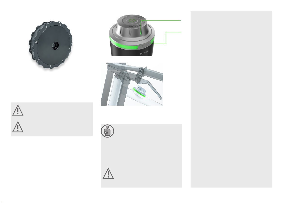
only supports you when you also pedal. The power of the mo-
tor assistance depends on the pedalling force and the selected
assistance mode. The harder you pedal, the more assistance
you get from the motor, and the higher the level of assistance,
the greater the thrust of the motor. If the speed of the Pedelec
exceeds 25 km/h, the motor assistance is automatically stopped.
If the speed subsequently drops below 25 km/h again, the motor
assistance is automatically reactivated. Since the drive system
has a maximum rated continuous power of 250W and supports
you up to a speed of 25km/h, your Pendix-equipped Pedelec is
legally equivalent to a bicycle. Therefore, the same legal require-
ments (in Germany the StVZO and STVO) apply to your Pedelec
as to a normal bicycle. Adhere to traic regulations and national
legal requirements. This part of the operating instructions gives
you specific information on how to handle the components of the
electric drive unit of your Pendix eDrive IN / INs and how to ride a
Pedelec. General information, e.g. on bicycle technology, can be
found in the original operating instructions for the bicycle and in
the other instructions supplied.
The Pendix eDrive IN / INs is intended for use in various bi-
cycle types such as city / trekking / touring bikes, mountain
bikes (race / cross-country), cargo bikes, folding bicycles,
recumbent bicycles. The exact range of use depends on the
bike model and is determined by the bicycle manufacturer.
Due to the higher loads the application of the
Pendix eDrive IN / INs in downhill-, freeride-,
BMX-cycles, dirtbikes and further related types
as well as operation in competition is prohibited.
The usage in static conditions (dyno, home gym)
is also prohibited.
Using clipless pedals in combination with Pendix
eDrive is prohibited.
The Pendix eDrive IN / INs is not designed for in-
stallation and eective use in bicycles for children
and juveniles up to the age of 14 years!
Before riding o, carefully read through the oper-
ating instructions for your Pendix eDrive IN / INs
and the operating instructions for the bicycle/
Pedelec.
Please never ride or roll standing on one side of
a pedal!
The manufacturer assumes no responsibility for
damage caused by not adhering to instructions.
Your Pedelec may only be used in accordance
with proper instructions. This is described in
the original operating instructions supplied with
the bicycle. Any other active use may result in a
technical breakdown or defect, causing accident
and injury! Responsibility for possibly defective
parts at purchase and all guarantee conditions
become invalid if the Pedelec/Pendix eDrive is
improperly used.
Please observe the maintenance intervals for
checking/replacing the components installed on
the bicycle in the Pedelec manual.
The intended operating temperature is -10°C to +50°C. The
temperature limits for storing the system are specified as
-20°C to +60°C.
Carry out the steps described in these instruc-
tions only. No other or dierent changes to the
Pendix eDrive IN / INs may be performed. Do not
take apart or open components!
Only replace parts that have become defective
or worn down, for example battery, charging
unit or sensors, by using original spare parts or
replacements either made by the manufacturer
or expressly allowed by the manufacturer. Note:
the manufacturer’s responsibility and/or guar-
antee lose their validity when non-contract parts
are used. If such parts are used, a loss of function
may result! In cases of defect or wear and tear,
always refer to a specialist/bicycle technician to
carry out the necessary repairs or replacement
using original parts or components only.
Improper and unprofessional operation of the motor and
manipulations to battery, charging unit and motor involve
great danger to health and damage of material. In any such
cases, Pendix refuses to accept any responsibility for dam-
age or accidents caused.
2. Introduction
3. Notes on electrics and
electronics
2.1 Field of application
question or problem. A lack of expertise can result
in accidents and/or severe injuries! If you have dis-
covered a defect, please proceed as described in
Chapter 7 „Default Measures“.
Before carrying out any kind of changes on your
Pedelec, switch o the electric system and remove
the battery.
Do not clean your Pedelec with a steam jet,
high-pressure cleaner or water hose. If you do so,
water can enter electric parts or the motor and de-
stroy the equipment.
The electric parts of your Pedelec combine to
form a high-power system. Remove the bat-
tery immediately when you see damage to
the electric system or particularly if, e.g. aer
a fall or accident, electric cables or parts are ex-
posed. Always refer to a specialist/bicycle tech-
nician for repairs, but also whenever you have a

EN
5
4. Example of product configurations
Pendix eDrive IN(s) system Single motor system in two-wheeler Double motor system in tricycle/four-wheeler
Motor(s) 1 wheel hub motor 2 wheel hub motors
Nominal voltage 36 V / 48 V DC
Power (max.) 700 W 1,400 W
Nominal continuous power 250 W 250 W*
Torque (max.) 70 Nm 140 Nm
Rotational speed (max.) 290 rpm
Motor(s) weight 4.7 kg 9.4 kg
Classification Pedelec up to 25 km/h
Protection class IP 65 (water jet protected)
Motor position in the wheel
Wheel mount double-sided one-sided
Perm. wheel load 150 kg 200 kg**
Rim Spoke rim Disc rim
Connectivity Pendix.bike PRO App via Bluetooth,
CAN-Bus via cable
Pendix.bike PRO App via Bluetooth,
CAN-Bus via cable
Manoeuvrability Start-up, push assistance Start-up, push and reverse assistance
Capacity 720 Wh 1,440 Wh
Battery The system can be combined with dierent types of batteries depending on the manufacturerThe system can be combined with dierent types of batteries depending on the manufacturer
* 125 W per motor
**** depending on design of motor mount by customerdepending on design of motor mount by customer

6
5. Overview components
Rotary handle/button
To activate the start assist
Hub motor
Voltage: 36 / 48V possible
Nominal power: 250 W*
Torque: max. 70Nm
* Continuous power per
eMachine = 250W / Number of
eMachines on vehicle
Battery (battery type depending on manufacturer)
5.1 Single motor system for single track vehicle
HMI
(on the frame or on the battery)
Display of the system status
Display of the support level
Bluetooth-interface
Bottom bracket bearing sensor
Bottom bracket
Square sha
Sha length: 128 mm
Bottom bracket thread: BSA 1.375“ x
24 TPI LH (FG34)
Crank thread: M8x1 RH
Bottom bracket mounting
Bottom bracket thread: BSA 1.375“ x
24 TPI RH (FG34)
Spacer ring electronic bottom
bracket
Wave washer
Crank screw
Screwed bushing aluminium

EN
7
Generator
(only for Pendix eDrive INs)
Torque max.: 65 Nm
Crank length: 172.5 mm
Pedal threat: 9/16“ x 20 LH (FG 14.3)
HMI
(on the frame or on the battery)
Display of the system status
Display of the support level
Bluetooth-interface
5.2 Double motor system for multitrack vehicle
Battery (battery type depending on manufacturer)
Rotary handle/button
To activate the start assist
Bottom bracket bearing sensor
Bottom bracket
Square sha
Sha length: 128 mm
Bottom bracket thread: BSA 1.375“ x
24 TPI LH (FG34)
Crank thread: M8x1 RH
Bottom bracket mounting
Bottom bracket thread: BSA 1.375“ x
24 TPI RH (FG34)
Spacer ring electronic bottom
bracket
Wave washer
Crank screw
Screwed bushing aluminium
Hub motor
Voltage: 36 / 48V possible
Nominal power: 125 W*
Torque: max. 70Nm
* Continuous power per
eMachine = 250W / Number
of eMachines on vehicle

8
The Pendix eDrive IN / INs is an eicient, high-power direct
drive system, working without gears or freewheeling. The
control system is already integrated. The Pendix eMachine
is designed as a hub motor and can be installed in spoke
wheels as well as other types of wheels.
Please note that aer extended tours with your
bicycle at a high support level, the temperature
of the housing of the motor can become very hot.
Should you want to conduct any work in region
of the motor, either let it cool down first or make
sure you wear suitable protective gloves.
Safety notes
• Do not drop or throw the battery and avoid
any strong impact. In such cases, liquid may
escape, causing fire or explosion.
• Do not use force when working with the battery.
• If the battery is deformed in any way, the inte-
grated protective mechanism can be damaged.
Here again, fire or explosion may result.
• Do not use the battery if it is damaged. The
liquid inside it may escape, causing damage to
the eyes and even blindness.
Remove the battery from the Pedelec if you wish
to transport it, for example by car.
• Also remove the battery whenever you want to carry
out any kind of work on the Pedelec, for example main-
tenance or assembly. Caution: there is a hazard of injury
if you activate the ON/OFF button inadvertently.
• Never open the battery. This can cause a short circuit.
Note: all and any guarantee claims become invalid if
the battery is opened.
• Never store or transport (carry) the battery together
with metal objects capable of causing a short circuit:
such objects can be, for example, paper clips, nails,
screws, keys or coins. A short circuit can cause a fire or
burns.
• Keep the battery away from heat, e.g. strong sun-
shine, which can lead to the battery being switched o
(self-protection above 60°C), as well as fire, there is a
risk of explosion.
• Protect your battery against water and other liquids.
Contact may cause damage to the protective circuit
and the protective mechanism of the battery. This can
result in fire or explosion.
• Do not use high-pressure equipment to clean your bat-
tery. To clean, use a damp cloth. Do not use aggressive
cleaning agents.
• Incorrect handling of the battery may cause liquid to es-
cape. This liquid can cause irritation and burns on the
skin. Avoid contact. If you do come into contact with the
battery liquid, wash the aected area with plenty of wa-
ter. If it comes into contact with your eyes, find a doctor
or medical expert immediately for help.
• If vapours escape due to improper use or damage, sup-
ply fresh air and seek medical advice if you experience
discomfort.
• Before undertaking a journey, the battery must be fully
attached in its holder. Otherwise, there is a danger that
it may fall out while you are riding.
• Prevent a total discharge of the battery at all costs. Oth-
erwise, irreversible damage to the battery cells results.
• This battery is designed only for use with Pendix electric
bicycle motors. Improper use or incorrect handling can
cause fires or injuries. Pendix assumes no guarantee or
responsibility of any kind for damage resulting from im-
proper use or treatment.
5.3 eMachine
5.4 HMI
LED shows the chosen
assistance level
USB-C
Interface
5.5 Battery
The Pendix HMI is a unit that can be installed directly on the
battery (Pendix ePower batteries) or as a single unit on the
bicycle (on other battery models). The HMI can be used to se-
lect the assistance levels, switch the system on and o, and
detect the charge or system status. Furthermore, the HMI has
a Bluetooth interface that connects the eDrive IN/INs system
with the Pendix.bike PRO app.
HMI integrated into the ePower battery
HMI integrated on the bicycle

EN
9
If your battery is out of use for a longer period, for
example for 3-6 months during a winter break, it
is best to store the battery at a charging level of
50 % – 80 %. In this way the battery does not age
as quickly as when it is fully charged. Don’t forget
to check the charging level once every 12 weeks,
recharging it, if the LED display on the battery
shows red. In this case always make sure that the
battery is not completely empty for a longer peri-
od of time, as a total discharge with irreversible
damage to the battery cells may result.
Storage of the battery
Store the battery in a dry and well-aired place. To counteract
a loss in the battery’s capacity, the best room temperature is
around 20° C (68 ° F).
If the battery is completely emptied (blinking red display for
ePower battery, observe indicator on battery for third-party
batteries) as a result of use, it must be recharged within 2-3
days to avoid damage.
Battery life and attrition
The battery is subject to wear (attrition). With increasing age
and use, it will lose in capacity and the corresponding maxi-
mum distance is reduced. The capacity loss is approximately
10 % per year. This is not a defect, but normal wear. From a
technical point of view, the battery is considered to be worn
out when 60 % of its capacity is reached.
You can continue to use it as before, though you should now
reckon with a lower capacity and a reduction in distance.
• Caution: magnetic fields around the battery plug/
holder also influence medical equipment such as for
example heart pacemakers. Always consult a doctor or
medically qualified person on this subject if in doubt.
Safety instructions for charging
• Use the charging unit for the corresponding
battery only. The battery charge voltage must
be the same as that of the charging unit. Other-
wise, a fire or an explosion may result.
• Make sure you are connecting to the proper
line (mains) power (voltage)! The label on the
charging unit indicates the necessary/ pre-
scribed line power. It must agree with the volt-
age coming from the power source.
• Do not touch the mains plug with wet hands.
You may receive an electric shock.
• Before use, check to see that the charging unit,
the cable and the plug are not damaged. If you
see any damage, do not use the charging unit.
You may receive an electric shock.
• Keep the charging unit away from children and
animals. Small children and animals may dam-
age the cable if they play with it. This can result
in an electric shock, a malfunction or a fire.
• The charging unit may be handled by children
(over 8 years) and persons with restricted phys-
ical, sensory or mental abilities only when they
are supervised by a responsible person.
• Aer this make sure that the charging unit is
clean. Otherwise you may receive an electric
shock.
• The battery must not be charged unattended.
When using the charging unit for the first few
times a smell may become perceptible. This is
the result of a normal production process. If this
happens, make sure your work room is well aired.
There is no danger to your health.
The charger is designed for usage in damp-free,
dry and ventilated environment. Do not expose
the charger to rain or hot conditions.
Remember that, aer a sudden temperature
change from cold to warm, condensed water can
form on the battery contacts.
You can recharge the battery at any time without shortening
its life. No memory eect occurs. Even an interruption of the
charging process does not damage the battery.
The ideal temperature for charging is between 15 and 25° C.
If the battery has a temperature below 0° C, it must not be
charged. The upper temperature limit for charging is 45° C.
If you bring the battery from a very cold environment to a
warmer one, a certain acclimatization time is required.
Remember that, aer a sudden
temperature change from cold to warm, con-
densed water can form on the battery contacts.
To avoid this, store the battery in the same place
as where you charge it.
During a charging process, place the charging
unit on an inflammable surface and make sure
that no easily inflammable materials (for exam-
ple paper, carton or textiles) are located nearby.
The charging unit warms up during the charging
process and there is a risk of fire while this takes
place.
Do not use the charging unit in damp places or near leaking
water. There is a risk of the charging unit overheating, catch-
ing fire or electric shock.
To charge the battery, first plug the Euronet plug into the
charging unit, and then plug the charging unit into a power
outlet. Now you can connect the battery to the charger.

10
When using the Power Station, just make sure the dot on
the battery is aligned with the dot on the Power Station. By
putting on the battery, the magnetic plug pulls itself to the
battery and is electrically connected. The connection is suc-
cessful when the LED indicator lights up.
Charging time by charger
Battery 160 W
ePower300 02:00 h
ePower500 03:10 h
ON/OFF button
The ePower (battery) is the power pack and central control
unit of the Pendix eDrive IN / INs. The battery supplies the
necessary energy for the drive of the bicycle, at the same
time the Pendix HMI including On/O button, a LED ring and
a rotating switch is integrated.
5.5.1 Pendix ePower
LED display
Hold the battery tightly when removing it.
It is heavy!
Installing the ePower on the wheel
Aer positioning the ePower (battery) in the holder, the LED
display lights up for a short moment before going out again.
This shows that the battery is connected with the motor. But
this does not mean that the motor is switched on.
To position the battery in the holder, the point on the battery
is placed over the corresponding empty point on the holder.
Now push the battery down into the base of the holder and
turn in the direction of the whole point until a connecting
noise is heard, and both whole points are positioned one
over the other. To remove the battery, please proceed in the
opposite sequence.
Charging the battery
A 160 W charger is included in the scope of delivery.
Read the information on the charger first before
commissioning.
Charging unit 160 W
Charging unit
Mains plug
Battery connector plug
To charge the battery safely, read the safety in-
structions on page 9 of this manual.

EN
11
LED display
Device
parameters
ePower300 ePower 500
Cell technology Li-Ion (lithium-ion)
Nominal voltage 48 V
Capacity 305 Wh 497 Wh
Connectivity Bluetooth
Charger data 160W - charger
Description B5C.904.081
Input 100-240V 50/60Hz 2.0A
Output 54.6V == 3.0A
The charging process is initiated when the battery is com-
bined with the charger. The LED indicator on the battery lights
up for 4 seconds in the colour of the current charge level and
then changes to a pulsating glow. As long as the charging
process continues, the LED indicator pulses. Its colour chang-
es according to the state of charge. When the battery is fully
charged, the LED indicator is turned o.
It is possible to turn o the pulsing of the LED display during
charging by pressing the on/o button once. The battery will
still continue to charge. If the on/o button is pressed again,
pulsing is reactivated or, if the battery is fully charged, a brief
flash in the colour green is displayed.
If the battery does not charge aer connection (e.g. charging
unit not connected to the mains), the LED indicator lights up
continuously for 30 seconds and is then switched o.
If the LED indicator flashes blue when you put it on, the bat-
tery is outside the temperature limits specified for charging.
Make sure that the temperature of the battery is in the range
of 0° to 45°C.
If you want to know the charge level of the battery, simply
press the on/o button briefly when the battery is not con-
nected. You can see the charge level of the battery by the
colour of the LED indicator at the top of the battery:
Green 100 % – 71 %
Yellow 70 % – 41 %
Orange 40 % – 16 %
Red 15 % – 6 %
Red blinking 5 % – 0 %
If the LED display shows red, the battery is almost empty and
should be charged.

12
USB-C connection
The ePower oers an USB-C interface which is suitable to
load typical devices like mobile phones and GPS devices as
well as for lamp systems.
The USB-C interface is activated if the battery is attached to
the bicycle and turned on.
The USB-C output can be activated or deactivated by press-
ing shortly the on-o switch button in case the battery is nei-
ther attached to the bicycle nor to the charging unit.
The LED ring dims and shows the current state of charge in
the appropriate colour when the USB is activated.
Output voltage: 5 V | Max. output current: 1.5 A
Flashlight mode
You can also use the battery as a light source. This functions
while charging or when the battery is not connected. Turn
the support setting to Sport. Push the ON/OFF button down
for 4 seconds, aer which the LED display shows a white
light. To switch the flashlight mode OFF either turn the set-
ting again or give the ON/OFF button a short push.
The setting process will be finished aer 30
seconds, even if you press the button longer.
For technical reasons, make sure that the mode
on the charging unit is terminated just before
conclusion of the charging process and is no
longer available. Separate the battery from the
charging unit to put it into operation again.
Note: according to duration of use, the rotating
switch in the flashlight mode can be very warm.
Brightness of the LED display (ePower300/500)
If you want, you can adjust the brightness of the LED display
as required. This functions when the bicycle is not in motion
or when the battery is not connected.
Please do not try to adjust the brightness while riding your
bicycle. Doing so is a safety hazard. Set the support mode
to Eco. Push the ON/OFF button down for 4 seconds, aer
which the LED display begins to show brightness levels in 5
steps. This continues as long as you keep the button pushed.
Release the button when the brightness level you want is
shown, and this value is saved. This brightness level is re-
tained until you make a new setting in the same way.
Resetting the battery
If it does happen that the battery no longer works, you have
the option of resetting it. For this, push the ON/OFF button,
no matter in what support setting, for 40 seconds. Aer that,
the LED display goes out and the battery is reset.
Safety U-bolt as bicycle lock
In its lower section, the Pendix battery has been fitted with
a withdrawable safety lock. If you ever do not intend to take
the battery with you, you can leave it plugged in, pull out the
bracket and pull a suitable bicycle lock through the bracket
to secure the battery to the bicycle.

EN
13
Battery holder
Release button
Battery
Charging level
display
Using the battery
To put the drive system into operation, the battery must be
inserted into the holder. Press the release button on the bat-
tery down and slide the battery into the holder. When insert-
ed, the battery starts automatically.
A charging level indicator is located on the front of the bat-
tery, which signals the current charge level of the battery.
ON
LED 1 Capacity approx. 20 %
LED 2 Capacity approx. 40 %
LED 3 Capacity approx. 60 %
LED 4 Capacity approx. 80 %
LED 5 Capacity approx. 100 %
Charging the battery
The battery must be removed from the holder for charging.
To remove the battery, press the release button and pull the
battery out of the holder.
Connect the mains plug to a 230 volt socket and then con-
nect the battery connector plug of the charger to the battery.
The charging process starts and ends automatically. The
charging time is approx. 14 hours.
The charging status of the battery can be checked by press-
ing the charging status indicator.
Battery connector
plug
Charging unit
Mains plug
Please make sure to also pay attention to the en-
closed manual of the battery manufacturer!
Device parameters Battery AES Classic
Cell technology LiFePO4
Nominal voltage 36 V
Capacity 669 Wh
(optionally 2-fold equipped)
Connectivity -
Charger data
Description WH-080AL4201200NO1
Input 100-240V 50/60Hz 2.0A
Output 42.0V ==1200mA
To charge the battery safely, read the safety in-
structions on page 9 of this manual.
5.5.2 AES Classic

14
Battery holder
Lock
Release button
Battery
Carrying handle
Charging level
display
Charging the battery
The battery must be removed from the holder for charging.
To remove the battery, open the lock with the supplied key.
Now press the release button and pull the battery out of the
holder.
Connect the mains plug to a 230 volt socket and then con-
nect the battery connector plug of the charger to the battery.
The charging process starts and ends automatically. The
charging time is approx. 4 h for the 36 volt system and ap-
prox. 5 h for the 48 volt system.
The charging status of the battery can be checked by press-
ing the charging status indicator.
Battery connector
plug
Charging unit
Mains plug
Device
parameters
Battery AES
2.0
36 V
Battery AES
2.0
48 V
Cell technology LiFePO4 LiFePO4
Nominal voltage 36 V 48 V
Capacity
528 Wh
(optionally 2-fold
equipped)
720 Wh (op-
tionally 2-fold
equipped)
Connectivity CAN-Bus CAN-Bus
Charger data 36 V system
Description XYH-180AL4154000N02-C8
Input 100-240V AC50/60 Hz 2.5A max
Output 41.5V == 4.0 A 166W
Charger data 48 V system
Description XYH-180AL5473000N02-C8
Input 100-240V 50/60Hz 2.5A max
Output 54.7V == 3.0 A 164.1W
Using the battery
To put the drive system into operation, the battery must be
inserted into the holder. Press the release button on the bat-
tery down and slide the battery into the holder. When insert-
ed, the battery starts automatically.
Optionally, a lock can be installed on the battery holder.
Secure the inserted battery against the by locking the lock
with the supplied key.
On the front of the battery is an LED charging status indica-
tor, which signals the current charging status of the battery.
To charge the battery safely, read the safety in-
structions on page 9 of this manual.
5.5.3 AES 2.0
Please make sure to also pay attention to the en-
closed manual of the battery manufacturer!

EN
15
Using the battery
To put the drive system into operation, the battery must be
inserted into the holder. When inserted, the battery starts
automatically. Secure the inserted battery against the by
locking the lock with the supplied key.
On the upper side of the battery is an LED charging status
indicator, which signals the current charging status of the
battery.
Lock
Carrying
handle
Battery
Charging level
display
Battery holder
Charging the battery
The battery must be removed from the holder for charging.
To remove the battery, open the lock and pull the battery out
of the holder.
Connect the mains plug to a 230 volt socket and then con-
nect the battery connector plug of the charger to the battery.
The charging process starts and ends automatically. The
charging time is approx. 10 hours.
The charging status of the battery can be checked by press-
ing the charging status indicator.
Battery connector
plug
Charging unit
Mains plug
Device
parameters
Battery AES Power Pack plus
Cell technology LiFePO4
Nominal voltage 48 V
Capacity 1,440 Wh
Connectivity CAN-Bus
Charger data
Description XYH-180AL5473000N02-C8
Input 100-240V 50/60Hz 2.5A max
Output 54.7V == 3.0 A 164.1W
To charge the battery safely, read the safety in-
structions on page 9 of this manual.
5.5.4 AES Power Pack plus
Please make sure to also pay attention to the en-
closed manual of the battery manufacturer!

16
Lock
Carrying
handle
Battery
Charging level
display
Battery holder
5.5.5 AES Super Pack
Using the battery
To put the drive system into operation, the battery must be
inserted into the holder. When inserted, the battery starts
automatically. Secure the inserted battery against the by
locking the lock with the supplied key.
On the upper side of the battery is an LED charging status
indicator, which signals the current charging status of the
battery.
Charging the battery
The battery must be removed from the holder for charging.
To remove the battery, open the lock and pull the battery out
of the holder.
Connect the mains plug to a 230 volt socket and then con-
nect the battery connector plug of the charger to the battery.
The charging process starts and ends automatically. The
charging time is approx. 10 hours.
The charging status of the battery can be checked by press-
ing the charging status indicator.
To charge the battery safely, read the safety in-
structions on page 9 of this manual.
Battery connector
plug
Charging unit
Mains plug
Device
parameters
Battery AES Super Pack
Cell technology LiFePO4
Nominal voltage 48 V
Capacity 1,440 Wh
Connectivity CAN-Bus
Charger data
Description XYH-180AL5473000N02-C8
Input 100-240V 50/60Hz 2.5A max
Output 54.7V == 3.0 A 164.1W
Please make sure to also pay attention to the en-
closed manual of the battery manufacturer!

EN
17
Battery holder
Release button
Battery
Charging level
indicator and ON
switch
Using the battery
To put the drive system into operation, the battery must be
inserted into the holder. Press the release button on the bat-
tery holder down and slide the battery into the holder. Press
the ON switch to start the battery.
On the front of the battery is an LED charging status indica-
tor, which signals the current charging status of the battery.
ON
LED 1 Capacity approx. 20 %
LED 2 Capacity approx. 40 %
LED 3 Capacity approx. 60 %
LED 4 Capacity approx. 80 %
LED 5 Capacity approx.
100 %
Charging the battery
The battery must be removed from the holder for charging.
To remove the battery, press the release button and pull the
battery out of the holder.
Connect the mains plug to a 230 volt socket and then con-
nect the battery connector plug of the charger to the bat-
tery. The charging process starts and ends automatically.
The charging time is approx. 4 hours. The charging status of
the battery can be checked by pressing the charging status
indicator.
To charge the battery safely, read the safety in-
structions on page 9 of this manual.
5.5.6 BMZ Cargo
Battery connector
plug
Charging unit
Mains plug
Device
parameters
Battery BMZ Cargo
Cell technology Lithium-ion
Nominal voltage 48 V
Capacity 807 Wh
Connectivity CAN-Bus
Charger data
Description BSC54604000
Input 100-240V 50/60 Hz 3.0A max
Output 54.6V == 4A
Please make sure to also pay attention to the en-
closed Manual of the battery manufacturer!

18
The actual range depends on many factors,
some of which can be actively influenced, but
some of which also result from conditions that
cannot be influenced, which should always
be taken into account when planning a route.
These dierent influences can be:
Can not be influenced:
Environmental influences such as wind,
temperature
Route influences such as underground, topogra-
phy, frequency of starts
Bicycle influences such as tire width tire profile,
weight, battery aging
Can be influenced:
Driving influences such as cadence, personal
eort, driving dynamics (braking / acceleration
behaviour), seating position, average speed
Bicycle influences such as air pres-
sure, smooth running of the compo-
nents, level of motor support
The information on range is based on optimum conditions.
These are influenced by the following factors:
• The higher the support setting (mode) used, the greater
the amount of electric energy used: this means the range
that can be covered is reduced.
• Ridingstyle:Youcansaveenergywiththeoptimumeective
use of your gear change system. In the low-
er gears you exert less energy, the support level
is not so high and the motor of your Pedelec consumes
less energy.
• Outside temperature: When temperatures are low, bat-
teries discharge more rapidly and the maximum range
covered is less.
• Weather and weight: In addition to the outside temper-
ature, prevailing winds also influence performance and
range. You need more power the stronger the wind is
against you. And if you are carrying an extra load, you also
need more energy to carry the additional weight.
• Technical condition of your Pedelec: If the pressure in
your tires is too low, this increases the resistance due
to friction, especially when the wheels are rolling over a
smooth surface such as asphalt (paving, concrete). The
range your Pedelec can cover is also reduced by a drag-
ging brake and/or a badly mounted chain.
• Charging level: The charging level shows the amount of
electricity stored in the battery at the moment in time.
More energy means a greater range.
• Battery capacity: The battery capacity function shows
the ability of a fully charged battery to supply a specific
amount of electricity. As the capacity of a battery de-
creases with age, the amount of storable energy in a fully
charged battery is also reduced.
• Pedalling frequency: The motor produces its optimum
level of eect at pedalling rates (frequencies) between 60
and 70 per minute. In this range, less energy is used than
at other frequencies, which allows a longer range.
At first, the battery / batteries (depending on the model,
one or more can be installed) must be inserted. Switching
on occurs when you briefly press the On/O button on the
HMI. With a Pendix ePower battery, the LED indicator lights
continuously in the colour of the current state of charge.
When using the Pendix HMI with a third-party battery, the
LED indicator lights up green continuously. Pressing it again
switches the drive o and the LED indicator goes out.
Only switch the system ON or OFF when the
bicycle is not in motion. This is to ensure that you
keep both hands on the handlebar while riding.
6. Useful notes about
the range
7. Functions of the
system
7.1 Switching on and o
LED shows the chosen
assistance level
USB-C
Interface

EN
19
Riding with the motor is only possible if the LED display
on the HMI is on permanently. This means that the motor is
activated so that it can support you the moment you start
pedalling.
Riding without the motor is possible with the eDriveIN /
INs both with and without the battery inserted. If the battery
is used, but there is no LED display on the HMI, this means
that the motor is deactivated and no support is provided.
With the eDrive INs serial hybrid system, driving without a
battery inserted is not possible.
The Pendix eDrive IN / INs has three assistance levels: ECO,
SMART and SPORT. You can set your system to any of these
using the rotating switch directly on the battery. The assis-
tance level is indicated by a luminous line below the font.
The assistance levels distinguish according to their strength
of performance. For the first ride, start at the weakest level
(ECO) to get used to the assistance.
The eDrive IN / INs can be equipped with a rotary handle or
an start assist button for the use of the starting assistance,
depending on the wheel model.
To use the start assist the drive must be activated. Pull the
brake and turn the rotary handle / press the start assist but-
ton. Aer about 1 second, you can release the brake to get
assistance up to 6 km/h without pedalling.
To use the reverse function, the drive must be activated.
Pedal backwards and simultaneously turn the rotary handle/
press the start assist button.
Depending on the configuration by the vehicle manufac-
turer, the light can be activated as soon as the battery is
plugged in, or by switching it on additionally. To do this, set
the rotating switch to SPORT mode. Press the On/O button
for 1 second to switch the light on/o.
During rolling or downhill driving, without pedalling, recu-
peration can be activated by pressing and holding the start
assist button.
This causes an electrical braking of the motor and thus of the
bicycle, whereby energy can be recovered.
Do not change the assistance level while riding.
Doing so is a safety hazard. Always keep both
hands on the handlebar while riding.
The braking eect resulting from recuperation
does not replace the mechanical brake in any
case! The braking behaviour should therefore al-
ways be made adapted to the situation.
Rotary handle
The reverse function is only activated for mul-
ti-track vehicles. This function is deactivated for
single-track vehicles where you have to keep your
balance to drive.
Start assist
button
7.2 Setting the assistance levels
7.3 Start assist 7.4 Reverse riding
7.5 Switching the light on and o
7.6 Recuperation
The assistance levels can be described as follows:
ECO • High duration level (supports up to 25 km/h or
15 ½ mph)
• Examples: flat country, extended tours, treated
flat ground (pavement, concrete, asphalt), phys-
ical training for non-professionals
SMART • Best mode for normal cycling activities (sup-
ports up to 25 km/h or 15 ½ mph)
• Examples: Cycling in town, slight gradients,
mostly untreated or non-solid ground
SPORT • High power (supports up to 25 km/h or 15 ½
mph)
• Examples: Hills, mountains, steep gradients,
loose or irregular surface, headwind

20
System
part Measure taken
Battery Make sure that the contacts at the bottom of the battery are free from impurities/dirt etc.
Make sure that the contacts at the bottom of the battery do not touch metal parts of any kind.
Check to see how hot the battery unit is. If necessary, allow it to cool down before checking again whether
functioning is in order.
Can the defect be corrected by charging the battery? Check accordingly.
Check to see whether the defect can be corrected by pushing the On/O button on the HMI down for 40 sec-
onds. This will perform a reset
Charging
unit
Make sure that the charging unit is plugged into the wall socket.
Make sure that the battery is properly connected to the charging unit.
Make sure that you are using the proper charging unit only.
eMachine Make sure that the plugs on the rear of the motor are tightly in place.
Make sure that the contacts of the plug on the battery holder are free of impurities or obstructions.
Make sure that the contacts of the plug on the battery holder do not touch any other metal parts or surfaces.
Make sure that there are no visible signs of damage along the cable connection between the motor and the
battery, and that all wires are properly laid out and accessible.
Check to see if the motor is warm. If necessary, allow it to cool down before checking again whether functioning
is in order.
Should your Pendix eDrive IN / INs not function properly an-
ymore, this can have dierent reasons. The following signals
have been installed to indicate the system in which the de-
fect has occurred:
• A blue light blinking at intervals of 0.5 seconds → there is
a defect in the battery or in the connection to the motor.
• Blue light blinking at intervals of 2 seconds → there is a
fault on the drive (the battery must be connected to the
drive)
• The LED display will indicate a defect as long as it is pres-
ent in the system. In such cases, you can switch the LED
display o by pushing the ON/OFF button down for 40
seconds.
You can use the Pendix.bike PRO App to read out the existing
error.
In order to do so, please use a Bluetooth connection to con-
nect the Pendix eDrive with the app as it is described in the
App manual. (Available for download at: app.pendix.de).
Use the diagnose function of the app in the "bike" menu to
read the error memory.
In case you do not use the Pendix.bike PRO App, you can
use the following table to check for an error yourself or have
them checked by a dealer. If you cannot rectify an error that
occurs yourself, please contact your dealer with both drive
and battery errors. The dealer can undertake further error di-
agnoses on site. If an exchange of parts is necessary, the han-
dling will always take place between the dealer and Pendix.
The Bluetooth interface is located in the Pendix HMI. De-
pending on the bicycle model, the HMI can be installed
directly on the battery, e.g. in the Pendix ePower, or as an
independent unit detached from the battery.
The Bluetooth can be activated and deactivated via the On/
O switch.
Requirement: The system is switched on, which is signalled
by the illuminated LED ring on the HMI.
The following steps must be performed for manual Blue-
tooth activation:
1. Turn the assistance level on the rotating switch to “SMART”.
2. Press the On/O switch for 4 seconds. The light ring starts
pulsing red, which means that the system is ready to connect
to the app.
3. Search for the HMI in the app, select it and connect it
If automatic Bluetooth is already activated, the light ring
does not start pulsing red, but is already ready for the com-
bination with the app as soon as the system is switched on.
Please do not connect via the on-board Bluetooth menu of
Android or iOS. This may lead to the fact that the connection
can no longer be established in the app..
On/O switch
Assistance levels
7.7 Switching Bluetooth on and o 8. In case of an error
This manual suits for next models
1
Table of contents
Other Pendix Bicycle Accessories manuals