3
When a Pendix eDrive has been installed into your bicycle, it
becomes a Pedelec. It is recommended to only retrofit bicy-
cles that comply with the known bicycle standards, such as
DIN EN14764, DIN EN14766 or ISO4210:2014.
1. Safety notes
In these instructions you will find four dierent symbols –
the symbol Note provides important information about
your new motor and how to use it, the symbol Caution
draws your attention to possible damage and/ or environ-
mental hazards, the symbol Danger warns you against
possible accidents and severe damage, including possible
injuries to your person. The symbol Torque marks sections
where a screw connection may only be tightened using a
torque wrench. The torque value given must be adhered
to. Whenever you see one of these symbols, there is a risk
that one of the hazards described may actually occur! Every
warning given is in a special box with a gray background for
emphasis.
Explanation of symbols
This symbol provides information about how
to handle the product or work with the respective
section in the system manual, which must first be
read through.
Caution: This symbol warns you against making
mistakes which can result in damage to material
or create an environmental hazard.
Danger: This symbol stands for a possible dan-
ger to your life and/ or health, if relevant instruc-
tions are ignored or not correctly followed. It also
draws your attention to the fact that correspond-
ing preventive measures must always be taken
beforehand.
Torque: Important screw connection! When
tightening up a threaded connection (screws),
the exact torque must be adhered to. The correct
tightening torque is either shown on the part in
question, or you will find it in the table of (torque)
tightening values on page 24 of this installation
manual. You must use a torque wrench to obtain
the proper torque. Parts which are not correctly
tightened can break or become loose! This can
cause severe falls and accidents!
2. Introduction
This installation manual describes the installation of the
Pendix eDrive on a bicycle. It is meant for bicycle mechan-
ics, technicians and people with equivalent knowledge and
technological comprehension.
Carry out the assembly steps described in these
instructions only. No other steps may be under-
taken or changes made to the system. Do not
take apart or open components! Improper and
unprofessional mounting of the motor and ma-
nipulations to battery, charging unit and motor
involve great danger to health and damage of
material. In any such cases, Pendix refuses to
accept any responsibility for damage or acci-
dents caused.
For installation of the Pendix eDrive in a bicycle
or onto a bicycle frame, expert technical back-
ground and experience are required, as well as
special tools and equipment. For installation of
the Pendix eDrive in a bicycle or onto a bicycle
frame, expert technical background and experi-
ence are required, as well as special tools and
equipment. In general we would recommend to
choose an authorized Pendix premium partner
to do the installation.
Read the manual carefully and follow all instruc-
tions step by step. Pay special attention to the
Safety Notes. Always keep the installation man-
ual in a safe place, and pass them on to all other
persons working with a Pendix eDrive.
The Pendix eDrive is not designed for installa-
tion and eective use in bicycles for children
and juveniles up to the age of 14 years!
Make sure that the bicycle is in a technical per-
fect and non-damaged condition. Check all
components for cracks, breaks, deformations
or heavy wear. If you notice anything of this
kind, do not use the bike any further and let a
Pendix premium partner check and repair it, if
possible.
The Pendix eDrive motor is not designed for
use in areas subject to explosion hazard or
equivalent.
Please read all supplied instructions for safe
handling of the drive system and the bicycle.
The “Original Pedelec Operaing Instructions”
provides special instructions on handling and
maintaining the bicycle and also on existing
residual risks.
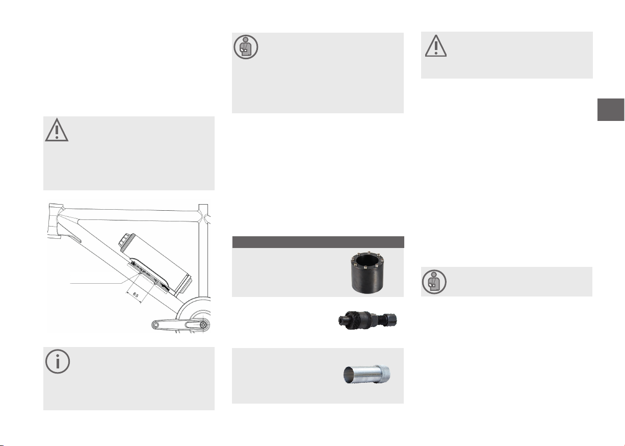
3. Field of application
The Pendix eDrive is provided for the following bicycle
types: City- / Trekking- / Touringbikes, Mountainbikes (Race/
Cross-Country), road bike, folding bike, recumbent bicycles
and further related types.
Because of the higher loads the application of
Pendix eDrive in downhill-, freeride-, BMX-cycles,
dirtbikes and further related types as well as op-
eration in competition is prohibited. The usage
in static conditions (dyno, home gym) is also
prohibited.
Using clipless pedals in combination with Pendix
eDrive is prohibited.