manuals.online logo
Brands
  1. Home
  2. •
  3. Brands
  4. •
  5. Penguin Edge
  6. •
  7. Computer Hardware
  8. •
  9. Penguin Edge KIT-IEEE-2500 User manual

Penguin Edge KIT-IEEE-2500 User manual

1 Box contents
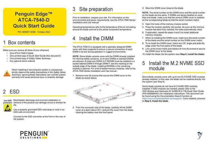
The Penguin Edge™ KIT-IEEE-2500 is used to convert
MVME2500ET boards with SCANBE handles to IEEE handles. This
kit does not include the VME board.
Make sure you receive all items of your shipment as shown in the
following table:
Tools needed:
• Phillips head screwdriver
• 1/8" hex nut driver
• 9/32" hex nut driver or open end wrench
NOTE: Care should be taken not to scratch the front panel with the
tools employed.
2 Safety
When installing or servicing the system or accessories,
strictly observe the safety precautions in the board’s
Safety Notes Summary. Ignoring these instructions can
void the system warranty and cause personal injury or
property damage.
3 ESD
Electrostatic discharge and incorrect installation or
removal of the card can damage circuit or shorten its
life. Use a properly grounded ESD wrist strap or work in
an ESD-safe environment. Connect to the ESD
connector at the front or the rear of the system.
4 Site preparation
Make sure that all environmental and power requirements defined in
the Penguin Edge™ MVME2500 Installation and Use manual are
met. Operating temperatures refer to the temperature of the air
circulating around the board and not to the actual component
temperature.
5 Remove front panel
assembly (SCANBE)
WARNING: Do not remove the heat frame from the board as
this will damage the thermal interface material and compromise
the integrity of the board.
Reference Diagram A to remove the front panel/SCANBE ejector
handle assembly from the board.
1. Remove front plate mounting hardware:
– Heat frame screw
– Reset switch hex nut and washer (set aside*)
– Mini DB-9 connector jack posts (set aside*)
2. Carefully pull the reset switch through the rear of the front panel,
leaving the wiring intact.
3. Remove two M2.5x14mm screws from the bottom of the board.
Note these screws mate with hex nuts on the top side of the
board.
4. Slide the Part Number and Logo panels off the ejector handles to
expose the internal screw. This action can be accomplished
using your thumb.
5. Unscrew and remove the internal screw in each handle.
6. Gently move each handle back and forth until the metal
alignment block and plastic lever (which are joined by a hidden
pin) are no longer trapped between the heat frame and PCB.
7. Carefully tilt the front panel assembly away from the board,
taking care not to break the light pipes (USER1, FAIL), and
remove from the PCA.
8. Remove the PMC/XMC slot cover and set aside*.
*The jack posts, reset switch hex nut and washer, and PMC/XMC
slot cover will be reused for the installation of the front panel/IEEE
ejector handle assembly.
Qty Part Number Description
1 6406849C02B MVME2500 front panel (rugged)
1 5506827A01A Ejector handle, top
1 5506828A01A Ejector handle, bottom
2 03-L6397C01A M2.5 x 11mm screw
2 03NL9004C46 M2.5 x14mm screws
2 0206815A01A M2.5 x 0.45 hex nuts
1 0306875A01A M2.5 x 10mm screw
1 3306812C02 Part number overlay
1 3306865E01A Logo overlay
1 6806800V46A Quick Start Guide (this document)
Penguin Edge™
KIT-IEEE-2500
Quick Start Guide
P/N: 6806800V46B JUNE 2022
Diagram A
Mini DB-9 Connector Jack Posts
Part Number
Panel
Internal Screw
Reset Switch Hex Nut and Washer
PMC/XMC Slot Cover
Internal
Screw
Logo
Panel
M2.5x14mm Screw
M2.5 Hex Nut
M2.5 Hex Nut
M2.5x14mm Screw
Heat Frame
Screw
Penguin Edge™ KIT-IEEE-2500 Quick Start Guide
Penguin Solutions™, 2900 S. Diablo Way, Suite 190, Tempe, Arizona 85282
6 Install front panel/IEEE
ejector handle assembly
Reference Diagram B to install the front panel/IEEE ejector handle
assembly to the MVME2500 board.
1. Carefully place the front panel assembly on the PCA using a
tilting motion, taking care not to break the light pipes (USER1,
FAIL).
2. Insert the reset switch into the panel, taking care to keep the
wiring intact.
3. Install front plate mounting hardware:
– M2.5x10mm heat frame screw included with kit
– Reset switch hex nut and washer set aside in step 4.1
– Mini DB-9 connector jack posts set aside in step 4.1
4. Slide the ejector handles onto each end of the front panel. Note
that the handles are not interchangeable – they can only go on
one way.
5. Press the red button on each ejector handle to move to the open
position.
6. Install the internal screw provided with each handle to secure
each handle to the front panel.
7. Install the M2.5x14mm screws and mating nuts to secure the
front panel assembly to the board.
8. Screw the M2.5x11mm screws into the ejector handles. Note that
these screws become captive and will be used to secure the
board to the chassis during board installation.
9. Insert the PMC/XMC slot cover set aside in step 4.8 into the front
panel.
10.Place the Logo overlay on the outer surface of the upper ejector
handle.
11. Place the part number overlay on the inner surface of the lower
ejector handle.
For more information on this product, see the
MVME2500 Installation and Use manual and other
related technical documentation, which can be found
by using the Documentation Search at
https://www.penguinsolutions.com/edge/support/.
Get More Information
For technical assistance or to report product damage or shortages,
contact your local Penguin Solutions™ sales representative or visit
https://www.penguinsolutions.com/edge/support/.
Technical Assistance
Penguin Solutions is a trade name used by SMART Embedded Computing, Inc., a
wholly owned subsidiary of SMART Global Holdings, Inc. Penguin Edge is a
trademark owned by Penguin Computing, Inc., a wholly owned subsidiary of
SMART Global Holdings, Inc. All other logos, trade names, and trademarks are
the property of their respective owners. These materials are provided as a service
to our customers and may be used for informational purposes only. For full legal
terms and conditions, please visit www.penguinsolutions.com/edge/legal/.
©2022 SMART Embedded Computing, Inc.
Diagram B
Part Number
Overlay
PMC/XMC Slot Cover
Logo
Overlay
M2.5x14mm Screw
M2.5 Hex Nut
M2.5x14mm Screw
Heat Frame Screw
M2.5x10mm
M2.5 Hex Nut
M2.5x11mm
Screw
M2.5x11mm Screw
Mini DB-9 Connector Jack Posts
Reset Switch Hex Nut and Washer

Other Penguin Edge Computer Hardware manuals

Penguin Edge ATCA-7XMMOD-SATAx User manual

Penguin Edge

Penguin Edge ATCA-7XMMOD-SATAx User manual

Penguin Edge ATCA-7540-D User manual

Penguin Edge

Penguin Edge ATCA-7540-D User manual

Penguin Edge MVME250 Series User manual

Penguin Edge

Penguin Edge MVME250 Series User manual

Penguin Edge PCIE-8130 User manual

Penguin Edge

Penguin Edge PCIE-8130 User manual

Penguin Edge PCIE-8120 User manual

Penguin Edge

Penguin Edge PCIE-8120 User manual

Penguin Edge ATCA-7XMMOD-1TB User manual

Penguin Edge

Penguin Edge ATCA-7XMMOD-1TB User manual

Penguin Edge MVME2500 User manual

Penguin Edge

Penguin Edge MVME2500 User manual

Popular Computer Hardware manuals by other brands

GRASS VALLEY HDSPARK PRO datasheet

GRASS VALLEY

GRASS VALLEY HDSPARK PRO datasheet

Dell 6 series user guide

Dell

Dell 6 series user guide

Ametek Reichert 13778 quick start guide

Ametek

Ametek Reichert 13778 quick start guide

Gembird PCMCIAX-USB32 user manual

Gembird

Gembird PCMCIAX-USB32 user manual

ekwb EK-XRES 100 Revo D5 Series INSTALLATION AND MOUNTING MANUAL

ekwb

ekwb EK-XRES 100 Revo D5 Series INSTALLATION AND MOUNTING MANUAL

Trinamic TMCL TMCM-142 Firmware manual

Trinamic

Trinamic TMCL TMCM-142 Firmware manual

Vecom EPBC-1000 user manual

Vecom

Vecom EPBC-1000 user manual

Magewell XI200DE-HDMI user guide

Magewell

Magewell XI200DE-HDMI user guide

Empire Gaming COOLER 120 manual

Empire Gaming

Empire Gaming COOLER 120 manual

ekwb EK-Quantum Kinetic FLT D5/DDC Body D-RGB installation manual

ekwb

ekwb EK-Quantum Kinetic FLT D5/DDC Body D-RGB installation manual

Lexicon LDI 12T - REV 1 manual

Lexicon

Lexicon LDI 12T - REV 1 manual

ekwb EK-Vector FTW3 RTX 2080 Ti Installation and mounting manuals

ekwb

ekwb EK-Vector FTW3 RTX 2080 Ti Installation and mounting manuals

DoorHan PCB-SH Programming instructions

DoorHan

DoorHan PCB-SH Programming instructions

Shuttle D230 quick guide

Shuttle

Shuttle D230 quick guide

National Instruments PCI-7041 user manual

National Instruments

National Instruments PCI-7041 user manual

National Semiconductor LMX9838DONGLE Hardware user's guide

National Semiconductor

National Semiconductor LMX9838DONGLE Hardware user's guide

NETGEAR WG511v2 installation guide

NETGEAR

NETGEAR WG511v2 installation guide

Eyevis openWARP2 user manual

Eyevis

Eyevis openWARP2 user manual

manuals.online logo
manuals.online logoBrands
  • About & Mission
  • Contact us
  • Privacy Policy
  • Terms and Conditions

Copyright 2025 Manuals.Online. All Rights Reserved.