Fuji Electric FRENIC-Lift LM2A Series User manual

Starting guide for DCP
3 ph 400 VAC 2.2 –45 kW
3 ph 200 VAC 4.0 –15 kW
1 ph 200 VAC 2.2 –4.0 kW
SG_LM2A_DCP_EN_1.0.0

Page 2of 18 Fuji Electric Europe GmbH
Version
Changes applied
Date
Written
Checked
Approved
1.0.0
First version
14.11.2022
J. Alonso
C. Arjona
C. Wolf
J. Català

Page 3of 18 Fuji Electric Europe GmbH
CONTENTS
0. Introduction..........................................................................................................................4
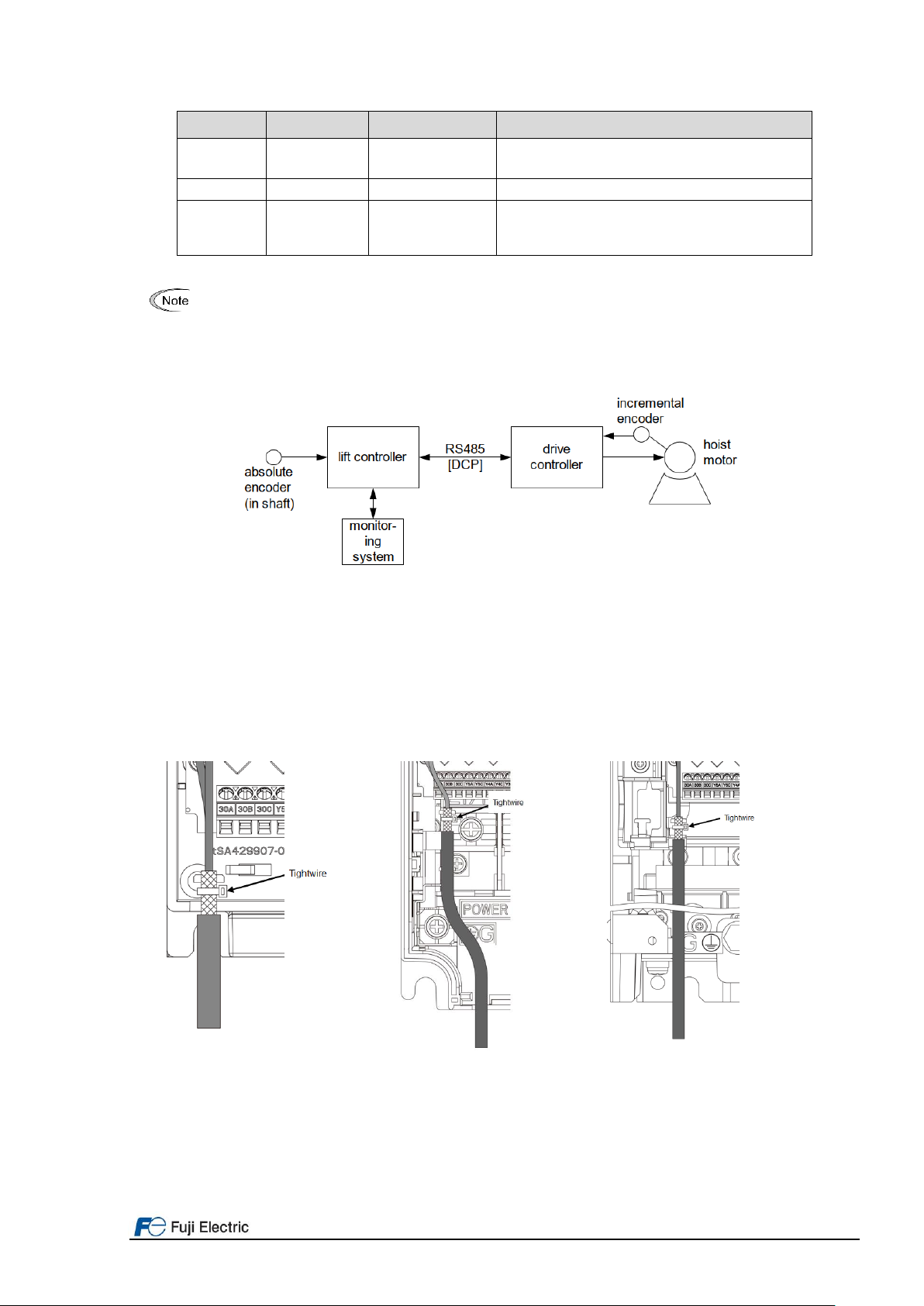
1. Connections.........................................................................................................................4
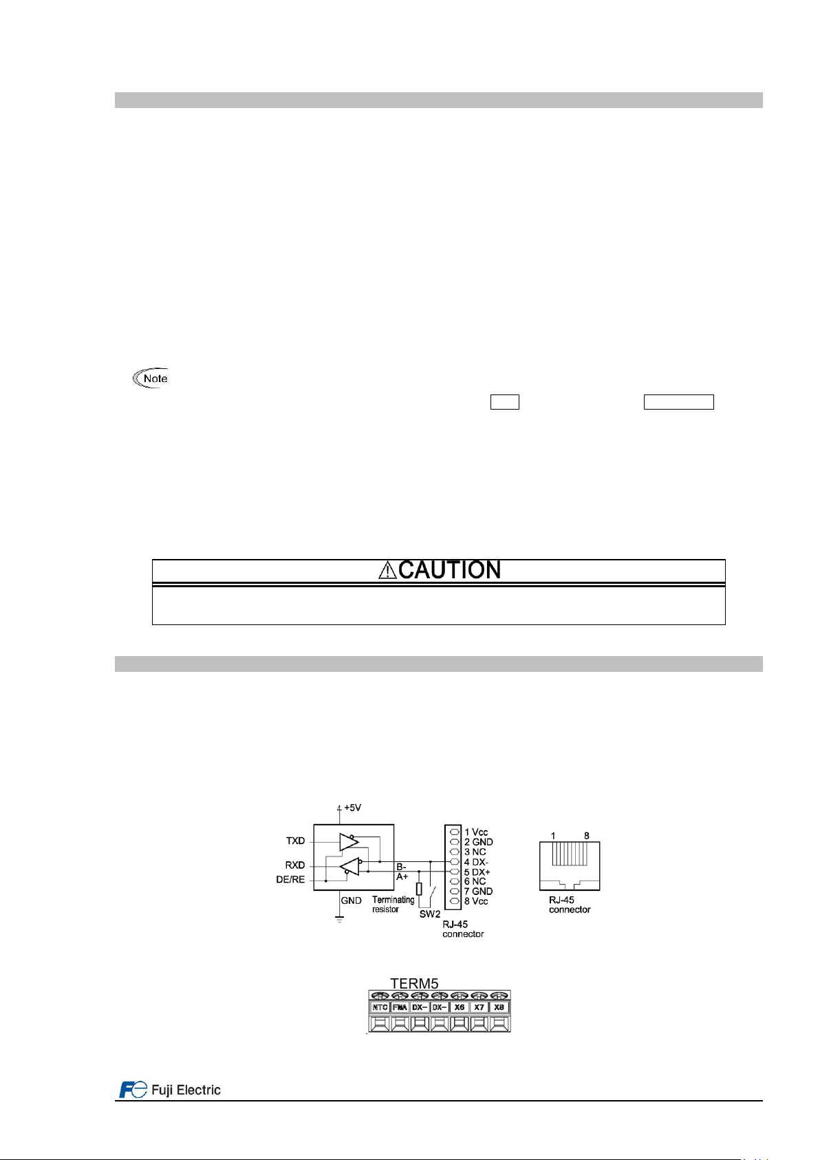
1.1 RS485 bus terminals.....................................................................................................4
1.2 Shield connection..........................................................................................................5
1.3 Terminal resistor............................................................................................................6
2. Remote display ....................................................................................................................6
2.1 Remote display keys .....................................................................................................6
2.2 Remote display menus..................................................................................................7
3. Basic setting.......................................................................................................................10
3.1 DCP bus setting ..........................................................................................................10
3.2 Lift / motor basic setting...............................................................................................10
3.3 Lift speeds...................................................................................................................11
4. Start-up..............................................................................................................................12
5. Lift speed profile settings....................................................................................................13
5.1 DCP 3 (Lift controller without absolute sensor system)................................................13
5.2 DCP 4 (Lift controller with absolute sensor system).....................................................14
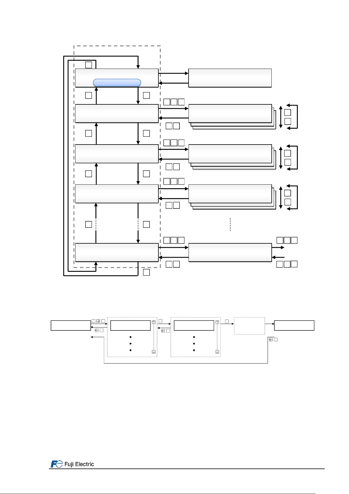
6. Signals timing diagram in DCP...........................................................................................15
6.1 DCP 3 (Speed mode)..................................................................................................15
6.2 DCP 4 (Remaining distance mode) .............................................................................16
7. Travel optimization (Remaining distance mode).................................................................17

Page 4of 18 Fuji Electric Europe GmbH
0. Introduction
Thank you very much for choosing FRENIC-Lift (LM2) inverter series.
This starting guide includes the basic information to operate FRENIC-Lift (LM2) via Drive Control Position (DCP). To
do so a lift controller based on DCP is necessary. This starting guide is written from end users point of view (not
developers).
FRENIC-Lift (LM2) inverter series has two models: LM2A and LM2C. Supported functions for each model is listed
below: - LM2A:
oDCPComChan
oDCP 3
oDCP 4
- LM2C:
oDCPComChan
oDCP 3
This starting guide is based on firmware version 1000 or later. For other software versions, please
contact with Fuji Electric technical department.
Firmware version (ROM) can be monitored on TP-E1U in 5_14 and on TP-A1-LM2 in PRG > 3 > 4
For extended information about the product and its use, refer to below mentioned documents:
- FRENIC-Lift LM2A series Reference Manual INR-SI47-1909_-E (RM).
- FRENIC-Lift LM2A series Instruction Manual INR-SI47-1894_-E (IM).
- FRENIC-Lift LM2C series Instruction Manual INR-SI47-2224_-E (IM).
- FRENIC-Lift LM2A series Starting guide SG_LM2A_EN_x.x.x (SG).
- FRENIC-Lift LM2C series Starting guide SG_LM2C_EN_x.x.x (SG).
DCP communications (3 or 4) is not compatible with CANopen 417. Therefore Remote display of
DCP cannot be used at same time than CANopen 417 virtual console.
1. Connections
1.1 RS485 bus terminals
FRENIC-Lift has two RS485 ports built-in. Port 1 is placed in RJ-45 connector (figure 1.1), Port 2 in TERM5 terminals
(figure 1.2). Table 1.1 shows the cross-reference between DCP signals, terminals and ports.
CAN bus terminal is placed in Terminals-PCB and it is called TERM1. Terminal is shown in figure 1.1; the meaning of
each terminal is described in table 1.1.
Figure 1.1. DCP Port 1 (RS485 1)
Figure 1.2. DCP Port 2 (RS485 2)

Page 5of 18 Fuji Electric Europe GmbH
Table 1.1. DCP bus terminal symbols description
Controller
Connection
in Port 1
Connection in
Port 2
Comments
DCP A
Pin 5
DX+
DCP B
Pin 4
DX-
Ground
Pin 2
or
Pin 7
11 (TERM 3)
This terminal might be connected in case of big
electric noise disturbance.
To prevent malfunction against the noise and ensure reliability please use twisted and shielded cables
for DCP bus.
Figure 1.3 shows a basic diagram of a DCP system where “drive controller” is the inverter. Absolute encoder (in
shaft) appears only in the systems where DCP 4 is implanted.
Figure 1.3. Connection via DCP
1.2 Shield connection
As explained before, it is recommended to use shielded cables. FRENIC-Lift has specific metal plates to connect the
shield of RS485 bus wires. The position of the metal plate depends on the inverter capacity. An example of metal
plate position and recommended connection method is shown in figure 1.4.
(FRN0011LM2A-7□/
FRN0018LM2A-7□)
(FRN0006LM2A-4□to
FRN0032LM2A-4□)
(FRN0039LM2A-4□/
FRN0045LM2A-4□)
(FRN0060LM2A-4□to
FRN0091LM2A-4□)
Figure 1.4. Metal plate for shield connection position

Page 6of 18 Fuji Electric Europe GmbH
1.3 Terminal resistor
RS485 bus are provided with a terminal resistor. Terminal resistors are connected/disconnected by switches placed
in Control PCB board shown in figure 1.5.
Terminal resistor for Port 1 is in SW2 and terminal resistor for Port 2 is in SW3.
Figure 1.5. Switches position and its meaning in Control PCB.
By default, the terminal resistor is disabled (OFF position). In case of DCP please switch them ON depending on the
Port used.
2. Remote display
FRENIC-Lift has implemented the Remote display function; therefore it can be operated by means of lift controller
keypad. Data can be monitored by lift controller screen as well. The way to access remote display and the buttons
functionality differs from each lift controller manufacturer. For additional information how to access remote display,
please check with lift control manufacturer.
2.1 Remote display keys
In table 2.1, the main function for each key on the controller keypad is described. The sign shown in the key column
might differ from the controller’s keypad.
Table 2.1. Remote display keys description
Key
Role / behavior
S
Move to the next group which is defined in current page.
If the next group is not defined, nothing happens.
In case of “Function setting group” or “F-code + Monitor”, move to corresponding function setting.
Request writing the value to the function code, then move to “waiting” page.
Decide to execute or not.
Move to previous page in current group.
In case of the first page, move to the last page.
Increment setting value toward maximum value.
Move cursor to “yes”.
Move to next page in current group.
In case of the last page, move to the first page.
Decrement setting value toward minimum value.
Move cursor to “no”.
or
+
Move cursor to the right.
In case the cursor is located at most right, move cursor to most left.
or
−
Move to the previous group which is defined in current page.
If the previous page is not defined, nothing happens.
Back to the original page without storing the function code data.

Page 7of 18 Fuji Electric Europe GmbH
Figure 2.1. Flow diagram to move across Remote display and its menus.
Figure 2.2 shows how to modify the setting of parameter F01 using Remote display keys. The setting of parameter
F01 is modified from 1 (default setting) to 2. Parameter is modified as soon as the screen showing the message
“Writing completed” appears.
F Code
****$******* F01 * 1
Speed command F01 * 2
Analog Reversible
SF code
-
Menu (F code) F code set
+
-
F01 * 2
Analog Reversible
SF code SWriting
Completed
-
Figure 2.2. Inverter parameter modification example.
2.2 Remote display menus
Remote display is organized by different menus; in each menu different information can be monitored or modified.
The name of the menus is listened below:
- Monitor
- I/O check
- Maintenance
- Alarm
- Function codes
- TrqBias
- Language setting
P r e s e n t s t a t u s
N o a l a r m
M o n i t o r
* $ * * * * * * * * * * *
P r e s e n t s t a t u s
A l a r m 0 O H 1
I / O C h e c k
* * $ * * * * * * * * * *
F o u t 1 0 . 0 0 H z
F o u t 2 0 . 0 0 H z
I o u t 0 . 0 0 A
V o u t 0 . 0 V
M a i n t e n a n c e
* * * $ * * * * * * * * *
T e r m F R E . . 1 2 3 4 5 6 7 8
* *
T i m e 0 h o u r
E D C 6 1 5 V
T e m p I 2 0 C
T e m p F 2 0 C
Language
* * * * * * * * * * * * $
Language English
Setting screen
S
S
−
+
S
−
+
S
−
+
S
−
+
S
−
+
Alarm occurs
Alarm reset
Home page
Menu group
Monitor group
I/O check group
Maintenance group
Language group

Page 8of 18 Fuji Electric Europe GmbH
Function codes are grouped by families. Families are F, E, C, P, H, y, L, L1, L2 and L3.
Two types of languages can be selected: English and German.
Figures below show which information can be monitored or modified in each menu.
Monitor
$*********** Fout1 0.00Hz
Fout2 0.00Hz
IOut 0.00A
VOut 00.0V
FRef 0.00Hz
SYN 0.00r/min
LIN 0.0m/min
TRQ 0%
TRQB 0%
TRQI 0%
TRQC 0%
E
Menu (Monitor) Monitor
or
RUN FWD REV IL LV TL
*
Internal frequency setpoint
Effective output frequency
Output current
Output voltage
Setpoint
Operation status [Direction, IL Current limit,
LV Undervoltage, TL Torque limit]
Syncronous speed
Linear speed
Reference torque current
Reference torque
Output torque
Torque bias
Figure 2.3. Monitor menu
I/O Check
*$********** Term FRE.12345678
* * * *
Link FRR.12345678FR
* * *
Out 12345.30ABC
* * *
12 0.0V
C1 0.0mA
V2 0.0V
THETAe 0deg
THETAre 0deg
THETAm 0
PPb 0000
AB 0P/s
Z 0P/s
I/O
or
Menu (I/O) EHardware digital inputs
status
Digital inputs status
through link (not DCP3)
Digital outputs status
Input voltage terminal 12
Input current terminal C1
Input voltage terminal V2
Output electrical angle
Magnet pole position angle (PP)
Detected mechanical angle (PS1)
Magnet binary pole position (PP)
Incremental signals frequency
Z signal (HTL / TTL)
Figure 2.4. I/O check menu

Page 9of 18 Fuji Electric Europe GmbH
Maintenance
**$********* Time 2h
EDC 646V
TempI 20C
TempF 20C
Imax 0.00A
Cap 0.0%
MTime 2h
TCap 2h
TFan 2h
NST 1
Wh 0kWh
485Err 0
ErrCode 0
RomVer. 0800
OPVer. 0000
OPName None
Maintenance
or
Menu (Maintenance) ETotat cumulative powered time
DC link voltage
Max. Internal temperature (/h)
Max Heatsink temperature (/h)
Maximum current (/h)
ReManing DC link capacitance
Cumulative run time of
the motor
Capacitors running time
Fan running time
Number of starts
Energy counter
Number of comms errors
Last comms error code
Inverter ROM version
Option card ROM version
Option card type name
Figure 2.5. Maintenance menu
Alarm
***$******** Alarm0 OH3
Sub 0 OV3 OC3
Alarm3 Er3
Sub 0
Fout1 0.00Hz
TRQ 0%
IOut 0.00A
VOut 0.0V
FRef 0.00Hz
Time 2h
EDC 646V
NST 1
TempI 20C
TempF 20C
Term FRE.12345678
* * * *
Link FRR.12345678FR
* * *
Out 12345.30ABC
* * *
Alarm
or
Menu (Alarm) Alarm details
RUN FWD REV IL LV TL
*
E E
Figure 2.6. Alarm menu

Page 10 of 18 Fuji Electric Europe GmbH
3. Basic setting
3.1 DCP bus setting
To enable the internal DCP interface it is necessary to setup some parameters. Basic setting is shown in table 3.1.
Table 3.1. Basic setting to enable DCP control
Function
code
Description
Setting
Comments
y10
RS485 Communication 1 (protocol selection)
5: DCP 3
6: DCP 4
Both ports cannot be used at same time
with DCP functionality.
y20
RS485 Communication 2 (protocol selection)
5: DCP 3
6: DCP 4
By setting y10=5 or 6 (y20) the inverter automatically sets internally baud rate=38.400 bps, Data bits=8, Parity=none
and Stop bits=1. In other words, the other y parameters will have no effect.
To enable all settings related to basic DCP communication it is necessary to reboot the inverter; it is recommended to
reboot also the Lift Controller. Power down until keypad and charging LED are OFF, then power ON again. After
rebooting, the controller will start the communication with the inverter.
When boot up sequence is finished, make sure lift controller does not display any error related to inverter (drive unit).
In affirmative case, please check with lift controller manufacturer.
3.2 Lift / motor basic setting
In DCP 4, in other words when we refer to Position control, it is very important to match lift speed and motor
parameters. Table 3.2 shows all relevant parameters related to lift speed and motor.
Table 3.2. Lift / Motor basic setting
Function
code
Description
Setting
Comments
C21
Speed command unit
0: rpm
Inverter will speak always in mm/s with the lift
controller.
The setting of this parameter affects only in the speed
units set on F04. Do not change default setting of this
parameter if not needed.
P01
Motor (Nº of poles)
-
Refer to LM2AStarting guide for this setting.
F03
Rated speed (maximum speed)
-
Motor speed to reach lift rated speed (L31).
L31
Elevator parameter (speed)
-
Lift speed at motor speed (F03).
F04
Base speed
-
Refer to LM2AStarting guide for this setting.
F05
Rated voltage
-
P02
Motor (rated capacity)
-
P03
Motor (rated current)
-
The programing order of these parameters is very critical. In other words, if the order shown in the table is not
followed, parameters which are already set can change its value. Please program C21, P01, F03 and L31 in this
order before than the rest of parameters.
Most of the parameters shown in table 3.2 are important for a proper motor control as well; make sure to set them
properly and to perform auto and/or pole tuning. In case of doubt, please refer to LM2A Starting guide.
Sometimes, the motor rated characteristics (rpm, pulley, sheave, gearbox, etc.) does not match with
the speed lift has been designed for. In other words, when motor turns at rated speed, can be that the
lift moves faster than expected. Use below formula to determine which are the motor rpm for the lift
characteristics.
iD rv
nrated
1,19
Where:
v: rated speed in m/s
r: Cabin suspension (1 for 1:1, 2 for 2:1, 4 for 4:1,…)
D: Pulley diameter in m
i : Gear ratio (in case of gearless = 1)
nrated: Motor rated speed (in rpm) at lift maximum speed

Page 11 of 18 Fuji Electric Europe GmbH
Example1: Lift with Permanent Magnets Synchronous Motor
Motor characteristics:
Motor rated speed=112,4 rpm
Motor rated voltage=360 VAC
Motor poles= 20
Motor pulley=340 mm
Motor gearbox= Gearless
Lift characteristics:
Rated speed= 1,00 m/s
Suspension= 1:1
nrated=(19,1*1)/(0,340*1)=56,17 rpm
Therefore, inverter setting will be:
- C21=0
- P01=20
- F03=56,17 rpm
- L31=1000 mm/s
- F04=112,4 rpm
- F05=360 VAC
- Etc.
Example2: Lift with Geared Induction Motor
Motor characteristics:
Motor rated speed=1413 rpm
Motor rated voltage=380 VAC
Motor poles= 4
Motor pulley=500 mm
Motor gearbox= 2/74
Lift characteristics:
Rated speed= 1,00 m/s
Suspension= 1:1
nrated=(19,1*1*71)/(0,500*2)=1413 rpm
Therefore, inverter setting will be:
- C21=0
- P01=4
- F03=1413 rpm
- L31=1000 mm/s
- F04=1500 rpm
- F05=380 VAC
- Etc.
3.3 Lift speeds
Lift speeds are programed in the C parameters. Table 3.3 shows a cross-reference between DCP specifications
speed and C parameters. Please note that depending on the mode selected (DCP 4 or 3) some speeds are available
or not.
Table 3.3. Cross-reference between DCP speeds and C parameters
DCP 3 Notation
DCP 4 Notation
Parameter
Description
V0
V0
C07
Crawl
VN
VN’
C05
Relevelling
VF
-
C04
Fast start (zero speed)
V1
-
C08
Intermediate3
VI
VI
C06
Inspection
V2
-
C09
Intermediate2
V3
V3’
C10
Intermediate1
V4
V4’
C11
Fast
Please note that these parameters have a default setting. Make sure the setting matches with your lift
installation, and if not, modify them accordingly. In case the speeds are set to zero, the lift will not
move.

Page 12 of 18 Fuji Electric Europe GmbH
4. Start-up
It is recommended to follow the start-up procedures described on FRENIC-Lift LM2A Starting guide. The start-up
procedure is different depending on the motor type (Induction Motor open or closed loop and Permanent Magnets
Synchronous Motor). Start-up procedure can be either done with FRENIC-Lift keypads (TP-A1-LM2 or TP-E1U) or
with Remote display (described on Chapter 2 of this manual).
In case that your lift controller controls the opening of the brake, make sure that it is disabled during Pole
tuning (for PMS motors) and Auto tuning (for Induction motors). If brake opens, the result of the tuning might
be not correct, additionally the lift car might move without control.
Make sure as well that the travel cancellation due to no movement function is disabled. If your lift controller has this
function activated, due to the non-movement of the lift car during the tuning, it will stop the tuning process. In such
case inverter will trip Er7 (SUB=7 or 24).
As described on the Starting guide, first movement should be carried out in inspection (auxiliary control mode). Check
if the driving direction matches with the commanded direction. If it does not match, change the bits 4 on the
parameter L99.
Table 4.1. Parameter L99 description
Function code
Description
Setting range
L99(bit4)
Control switch (Rise direction definition for DCP)
Bit4=0 (xxx0xxxx) -> FWD
Bit4=1 (xxx1xxxx) -> REV
At this point, it is important to make sure that the speed monitored in inverter keypad and real lift speed (Speed
shown by shaft encoder or controller) is the same. If this is not the case, check the setting on the parameter F03
(maximum speed) and L31 (Elevator speed) as described in Chapter 3.2.
In case of TP-A1-LM2, lift speed is shown on below screen (PRG>3>1 [1/8]):
In case of TP-E1U, you can monitor lift speed in below parameters:
- 3_08: Motor speed / Detected speed (rpm)
- 3_33: Lift speed (mm/s)
Additionally, in parameter W209 PRG > 6 > 3 you can monitor Command byte and Status byte from DCP frame.
Table 4.2 shows W209 bit description.
Table 4.1. W209 parameter bit description
Command byte
Status byte
B7
B6
B5
B4
B3
B2
B1
B0
S7
S6
S5
S4
S3
S2
S1
S0
Error in last reply message
Distance (0:actual, 1:desied)
Speed change
Travel direction (0:Up,
1:Down)
Speed mode
V0 off switch
Travel command (only in
DCP3)
Drive controller enable
Error in last reply message
Open mechanical brake
(BRKS)
Desired distance / speed
acceptance
Speed detection. 0: v>=0,3
m/s, 1: v<0,3 m/s (/FDT)
General fault active
Advance warning active
Travel active
Drive controller ready

Page 13 of 18 Fuji Electric Europe GmbH
5. Lift speed profile settings
The speeds used in DCP, either 3 or 4, are defined in table 3.3. Ramps and s-curves will be defined by the speed I’m
coming from to the speed I’m going to (as described in the Starting guide). In the next sub chapters, you can find
most used speed profiles depending on the mode.
5.1 DCP 3 (Lift controller without absolute sensor system)
L19 Time (s)
E12
E13
E15
L24 L25
L27
L27
L26
V0
V4
Figure 5.1. V4 long travel
L19 Time (s)
E10
E11
E15
L22 L23
L27
L27
L26
V0
V3
Figure 5.2. V3 long travel
L19 Time (s)
F07
F08
E15
L20 L21
L27
L27
L26
V0
V2
Figure 5.3. V2 long travel
F07 Time (s)
E15
L27
L27
V0
Figure 5.4. Crawl travel
Time (s)
F07
F08
V0
VI
Figure 5.5. Inspection travel using VI

Page 14 of 18 Fuji Electric Europe GmbH
Time (s)
F07
V0
VI
Figure 5.6. Inspection travel using V0
L19 Time (s)
F07
L20
VN
Figure 5.7. Relevelling travel without electric stop
L19 Time (s)
F07
L20
VN F07
Figure 5.8. Relevelling travel with electric stop
5.2 DCP 4 (Lift controller with absolute sensor system)
L19 Time (s)
L24 L25
L28
E12
E13
V4'
Figure 5.9. V4’ long travel
L19 Time (s)
L22 L23
L28
E10
E11
V3'
Figure 5.10. V3’ long travel
L19 Time (s)
L22 L23
L28
E10
E11
VN'
Figure 5.11. VN’Relevelling travel

Page 15 of 18 Fuji Electric Europe GmbH
6. Signals timing diagram in DCP
In the following chapter, we will explain the sequence of signals coming from Command byte, its answer from Status
byte and the effect on lift travel sequence. Additionally you will see a cross-reference with the inverter functions. We
divide the chapter between DCP 3 (Speed mode) and DCP 4 (Remaining distance control).
6.1 DCP 3 (Speed mode)
Figure 6.1 shows a complete timing diagram and signals sequence in case of DCP 3 lift movement. The movement
analysed uses V4 long travel speed. On the first part of the graphic (top), we see speed profile, after speed signals in
command and status byte. Finally, the cross-reference between command and status byte signals and inverter
signals.
L19 Time (s)
E12
E13
E15
L24 L25
L27
L27
L26
V0
V4
F25
ON
ON
ON
0=Upwards, 1=Downwards
ON
ON
ON
ON
ON
ON
ON
ON
B0
B1
B2
B3
B4
S0
S1
S2
S3
S4
S6
FWD/REV
SW52-2
BRKS
Output current
L85 L82
ON
L83
H67+L56
E32
ON
L86
Figure 6.1. DCP 3 time and signals sequence diagram.
Sequence description:
Start:
From the inverter point of view, if all is correct (input voltage existent, no alarm, etc.); we have bit S0 that means
inverter ready for a lift movement.
At starting, lift controller activates command byte bits 0, 3 and 4 (Drive enable, speed mode and direction). This
generates that inverter activates internally FWD or REV command (Up or down) and consequently it activates the
output to close the main contactors (SW52-2).
Then command byte B3 goes to zero and B1 and B2 to one (Travel command for DCP 3 and v0 off switch OFF). In
parallel, the inverter will set S1 bit to one to show a travel has started (when L85 time has elapsed) and brake will
open (when L82 time has elapsed).
The start sequence finish with the acceleration phase (s-curves and ramp). The parameters to adjust acceleration
ramp and s-curves differs depending on the selected speed or DCP 3 and 4. For additional information, refer to
Chapter 5.
Stop:
When the lift controller sets to zero B2 bit we can say stopping phase starts. At this point, the inverter decelerates the
motor from V0 (C07) speed to zero speed to reach target floor.
During the deceleration phase, the stopping speed level (F25) is reached. This speed level initiates the timers to
close the brake (L83) and to hold zero speed at stop (H67).
After zero speed holding time and demagnetization ramp times are finished (H67+L56) the delay time to open main
contactors starts (L86).
Trip is finished when controller sets to zero B0 bit on command byte.

Page 16 of 18 Fuji Electric Europe GmbH
6.2 DCP 4 (Remaining distance mode)
Figure 6.2 shows a complete timing diagram and signals sequence in case of DCP 4 lift movement. The movement
analysed uses V4’ as maximum speed. On the first part of the graphic (top), we see speed profile and Remaining
distance, after speed signals in command and status byte. Finally, the cross-reference between command and status
byte signals and inverter signals.
L19
Time (s)
E12
E13
L24 L25
L28
V4
F25
ON
ON
0=Upwards, 1=Downwards
ON
ON
ON
ON
ON
ON
ON
ON
B0
B1
B2
B3
B4
S0
S1
S2
S3
S4
S6
FWD/REV
SW52-2
BRKS
Output current
L85 L82
ON
L83
H67+L56
E32
ON
L86
Remaining
distance
Figure 6.2. DCP 4 time and signals sequence diagram.
Sequence description:
Start:
From the inverter point of view, if all is correct (input voltage existent, no alarm, etc.); we have bit S0 that means
inverter ready for a lift movement.
At starting, lift controller activates command byte bits 0, 3 and 4 (Drive enable, speed mode (DCP 3) and direction).
This generates that inverter activates internally FWD or REV command (Up or down) and consequently it activates
the output to close the main contactors (SW52-2).
Then command byte B3 goes to zero and B2 to one (v0 off switch OFF). At same time, lift controller will update
Remaining distance, which shows how far the lift from the target floor is. In parallel, the inverter will set S1 bit to one
to show a travel has started (when L85 time has elapsed) and brake will open (when L82 time has elapsed).
The start sequence finish with the acceleration phase (s-curves and ramp). The parameters to adjust acceleration
ramp and s-curves differs depending on the selected speed or DCP 3 and 4. For additional information, refer to
Chapter 5.
Stop:
The inverter will start to decelerate the motor to zero speed (and target floor) when Remaining distance and
Deceleration distance are equal, at this point we can say stopping phase starts.
During the deceleration phase, the stopping speed level (F25) is reached. This speed level initiates the timers to
close the brake (L83) and to hold zero speed at stop (H67).
After zero speed holding time and demagnetization ramp times are finished (H67+L56) the delay time to open main
contactors starts (L86).
Trip is finished when controller sets to zero B0 bit on command byte.

Page 17 of 18 Fuji Electric Europe GmbH
7. Travel optimization (Remaining distance mode)
There are different parameters to optimize the travel in Remaining distance mode; these parameters are
implemented to get the best stopping accuracy.
The parameters are listed in table 7.1.
Table 7.1. Parameters related to stop accuracy in position mode
Function
code
Description
Default setting
L352
Early deceleration distance
45 mm
L353
Early deceleration minimum speed
0.0%
L352 and L353 are parameters implemented in order to compensate the communications delay, which may deal with
a wrong stopping. Figure 8.1 shows the effect of L352 and L353 due to early deceleration distance.
Distance
(mm)
Speed
L352
t
t
Vmax (F03)
V=Vmax*L353
Remaining
distance
Braking
distance
Figure 7.1. Early deceleration distance to compensate communications delay.
As the lift speed has a very important role as well on communication delays and positioning, L352 default setting
might be not correct for any lift speed. In other words, depending on lift speed, due to L352 default setting lift
behaviour might be erratic. You can detect erratic behaviour because lift stops in a random floor before target floor.
L352 default setting is based on a lift with 1000 mm/s rated speed and with certain communication delay. If your lift
has lower rated speed or there is no communication delay, most probably you will have to reduce L352 value as well.
L353 specifies from which speed the early deceleration distance is going to be applied. As default setting is 0.0 %,
compensation will be applied for any speed.

Page 18 of 18 Fuji Electric Europe GmbH
CONTACT INFORMATION
Fuji Electric Europe Headquarters
Fuji Electric Europe GmbH
Goethering 58
63067 Offenbach am Main
Germany
Tel.: +49 69 669029 0
Fax: +49 69 669029 58
www.fujielectric-europe.com
Swiss Branch
Fuji Electric Europe GmbH, Swiss Branch
Rietlistrasse 5
9403 Goldach
Tel.: +41 71 858 29 49
www.fujielectric-europe.com
French Branch
Fuji Electric Europe GmbH, French branch
265 Rue Denis Papin
38090 Villefontaine
Tel.: +33 4 74 90 91 24
Fax: +33 4 74 90 91 75
www.fujielectric-europe.com
UK Branch
Fuji Electric Europe GmbH, UK Branch
Bedford i-Lab, Stannard Way, Priory Business Park,
MK44 3RZ Bedford
Tel.: +44 1234 834 768
www.fujielectric-europe.com
Spanish Branch
Fuji Electric Europe GmbH, Sucursal en España
Carrer dels paletes 8, Edifici B, Primera Planta B
Parc Tecnològic del Vallès
08290 Cerdanyola (Barcelona)
Tel.: +34 935 824 333
Fax: +34 935 824 344
www.fujielectric-europe.com
Italian Branch
Fuji Electric Europe GmbH, Filiale Italiana
Via Rizzotto 46
41126 Modena (MO)
Tel.: +39 059 4734 266
Fax: +39 059 4734 294
www.fujielectric-europe.com
Subject to change without prior notice
Other manuals for FRENIC-Lift LM2A Series
1
Table of contents
Other Fuji Electric DC Drive manuals

Fuji Electric
Fuji Electric FRENIC-AQUA series User manual

Fuji Electric
Fuji Electric frenic-hvac User manual

Fuji Electric
Fuji Electric FRENIC-Eco Series User manual

Fuji Electric
Fuji Electric Frenic lift How to use

Fuji Electric
Fuji Electric Frenic lift User manual

Fuji Electric
Fuji Electric frenic-hvac User manual