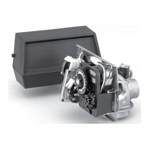
Pentair TRACETEK TTDM-128 User manual
Other Pentair Control Unit manuals

Pentair
Pentair LINCOLN 84976 Owner's manual
Pentair
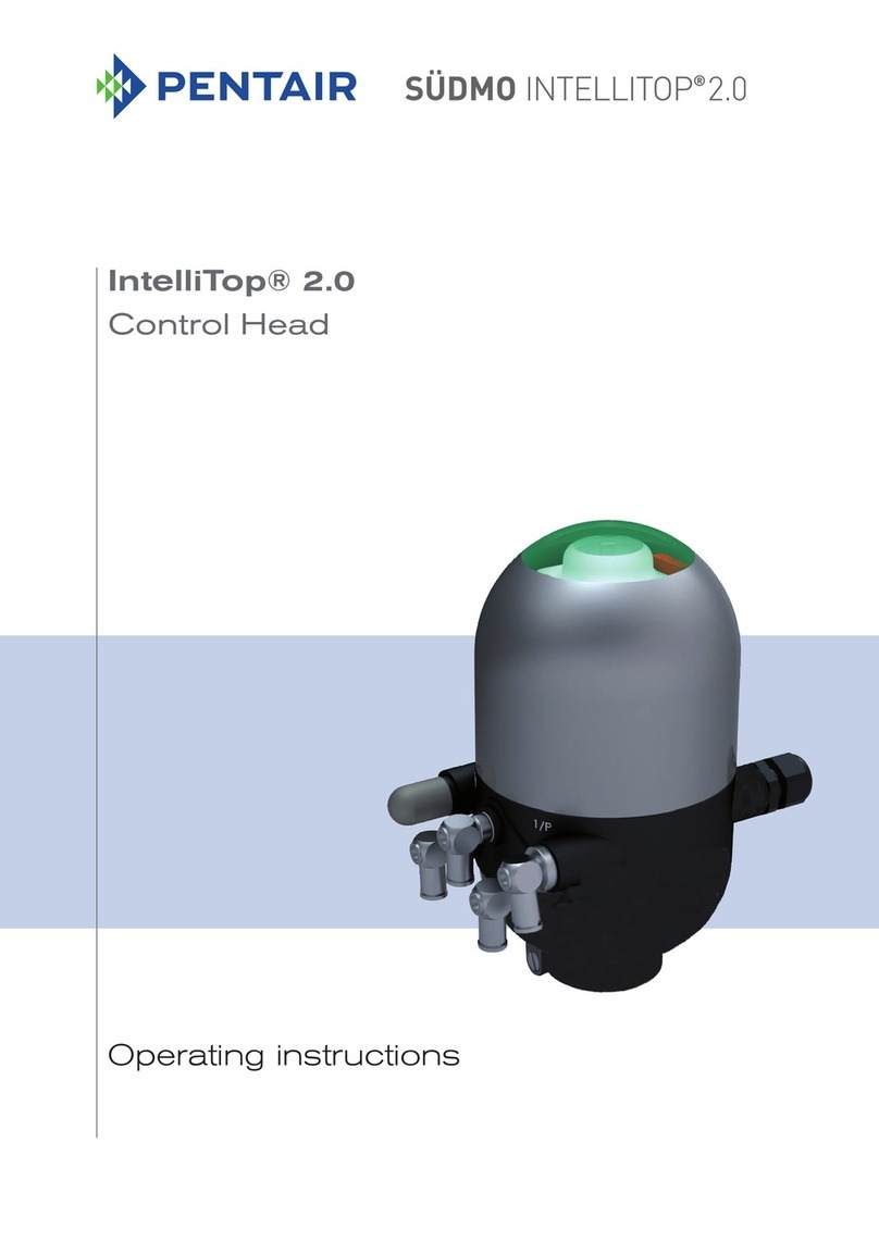
Pentair SUDMO IntelliTop 2.0 User manual
Pentair
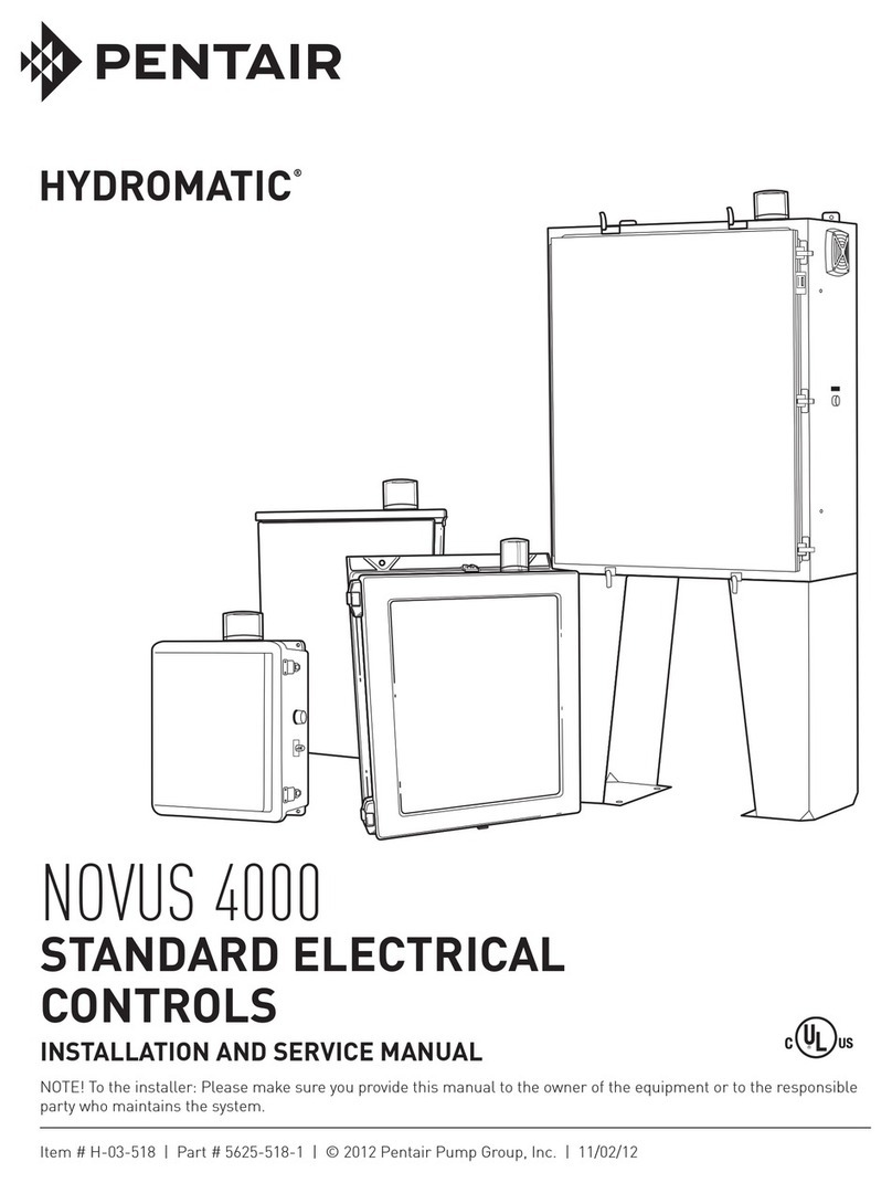
Pentair Hydromatic Novus 4000 Manual

Pentair
Pentair FLECK 5800 User manual

Pentair
Pentair HYPRO PROSTOP-E User manual
Pentair
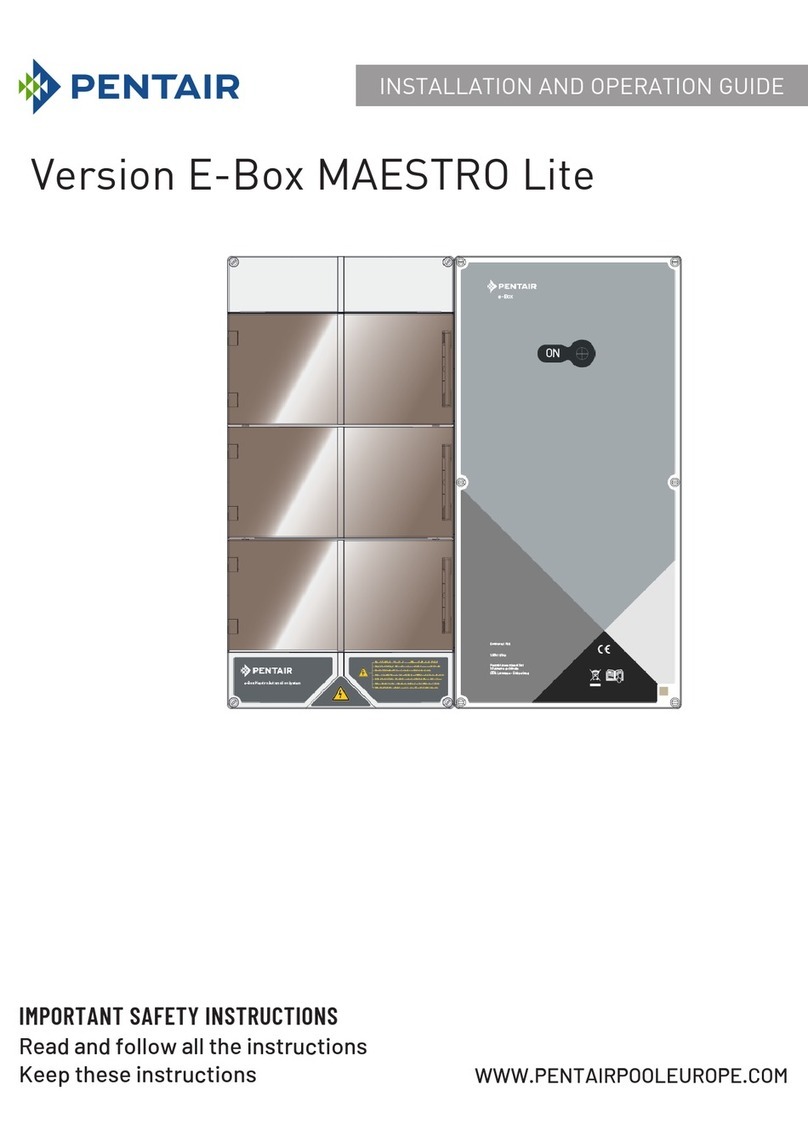
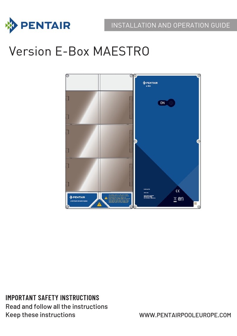
Pentair E-Box MAESTRO Operating instructions

Pentair
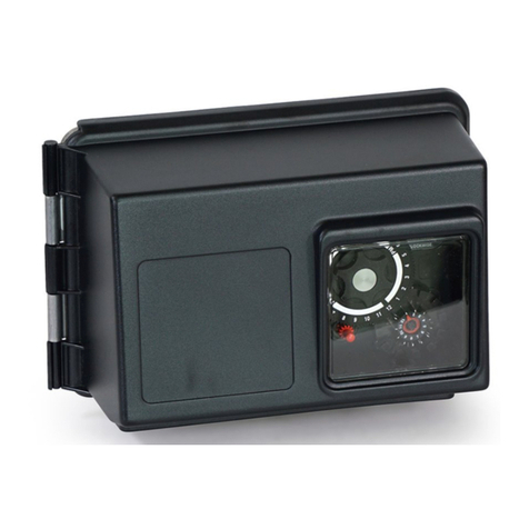
Pentair Fleck 2850 User manual
Pentair
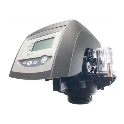
Pentair FLECK 2750 Downflow User manual
Pentair
Pentair AUTOTROL 742 Series User manual

Pentair
Pentair Goyen Precision P1 User manual

Pentair
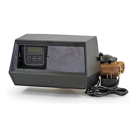
Pentair AUTOTROL 363 User manual
Pentair
Pentair FLECK 9000 SXT User guide

Pentair
Pentair Anderson Greenwood 93 Series User manual

Pentair
Pentair BAA A390-D.03 Select User manual

Pentair
Pentair ERICO CADWELD PLUS User manual
Pentair
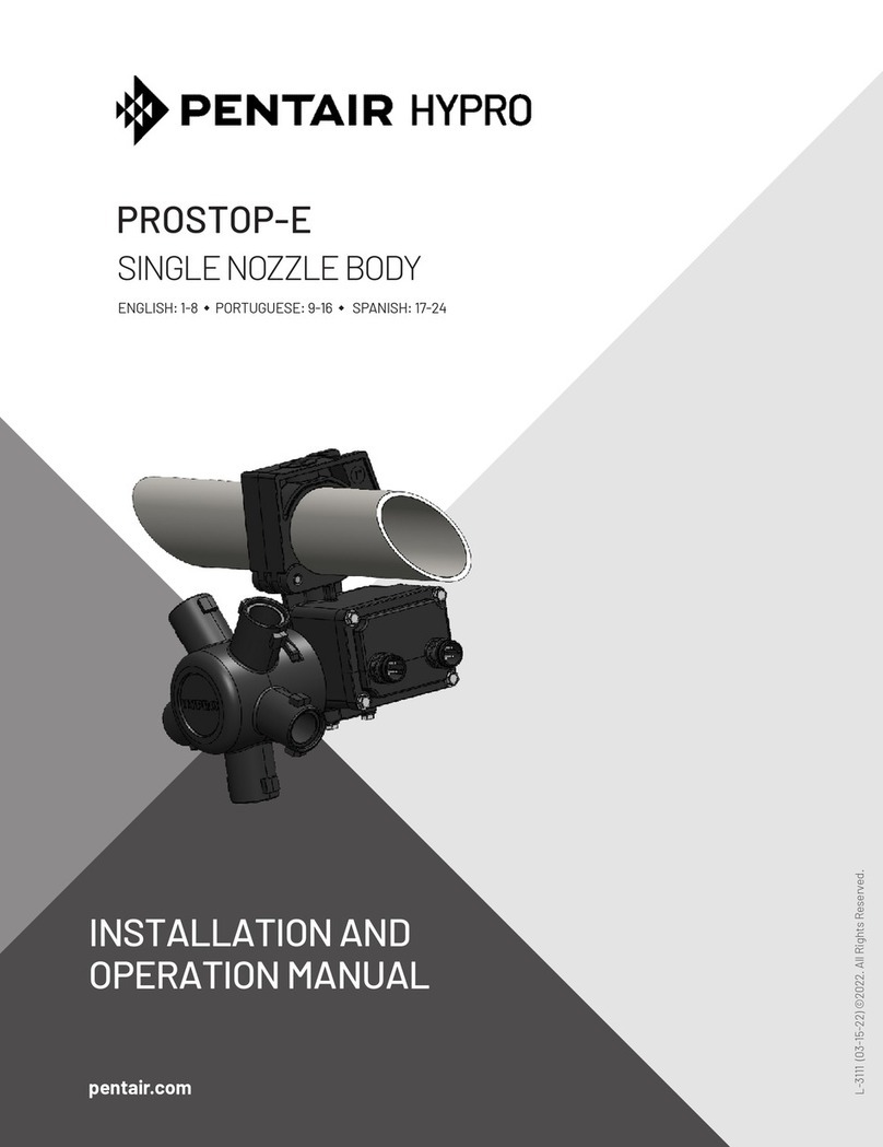
Pentair HYPRO PROSTOP-E User manual

Pentair
Pentair AUTOTROL 368 User manual

Pentair
Pentair FLECK 2900S User manual
Pentair
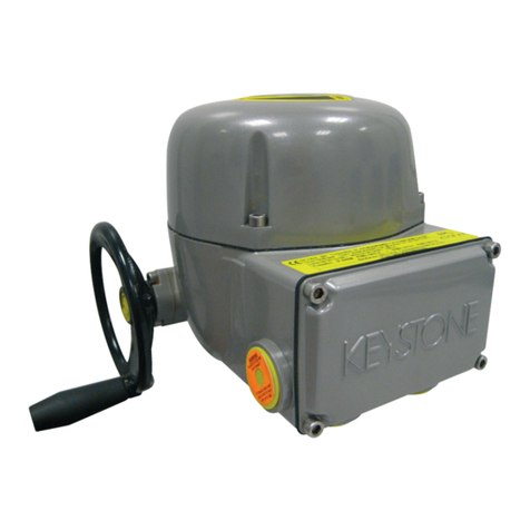
Pentair KEYSTONE OM3 User manual

Pentair
Pentair FLECK NXT User manual
Popular Control Unit manuals by other brands

Festo
Festo Compact Performance CP-FB6-E Brief description

Elo TouchSystems
Elo TouchSystems DMS-SA19P-EXTME Quick installation guide

JS Automation
JS Automation MPC3034A user manual

JAUDT
JAUDT SW GII 6406 Series Translation of the original operating instructions

Spektrum
Spektrum Air Module System manual

BOC Edwards
BOC Edwards Q Series instruction manual

KHADAS
KHADAS BT Magic quick start

Etherma
Etherma eNEXHO-IL Assembly and operating instructions

PMFoundations
PMFoundations Attenuverter Assembly guide

GEA
GEA VARIVENT Operating instruction

Walther Systemtechnik
Walther Systemtechnik VMS-05 Assembly instructions

Altronix
Altronix LINQ8PD Installation and programming manual
