Pentair Schroff AdvancedTCA 11596-100 User manual

AdvancedTCA Shelf, 14-slot
Service Manual
Product Numbers:
11596-100
11596-101
11596-102
11596-103
Revision: R1.1, July 23, 2008
Doc-No: 63972-171

Impressum:
Schroff GmbH
D-75334 Straubenhardt, Germany
The details in this manual have been carefully compiled and
checked - supported by certified Quality Management System
to EN ISO 9001/2000
The company cannot accept any liability for errors or misprints.
The company reserves the right to amendments of technical
specifications due to further development and improvement of
products.
Copyright © 2008
All rights and technical modifications reserved.
Rev. Date updated Change
R1.0 November 24, 2006 Initial Release
R1.1 July 23, 2006 Chapter 3.4 added

14-Slot AdvancedTCA Shelf
11596-100/-101/-102/-103
www.a-tca.com / www.schroff.biz I R1.1, July 23, 2008
Table of Contents
1 Safety................................................................................................................. 1
1.1 Safety Symbols used in this document................................................................ 1
1.2 General Safety Precautions................................................................................. 1
1.3 References and Architecture Specifications........................................................ 2
1.4 Product Definition ................................................................................................ 2
1.5 ESD Wrist Strap Terminals.................................................................................. 3
1.6 Terms and Acronyms........................................................................................... 4
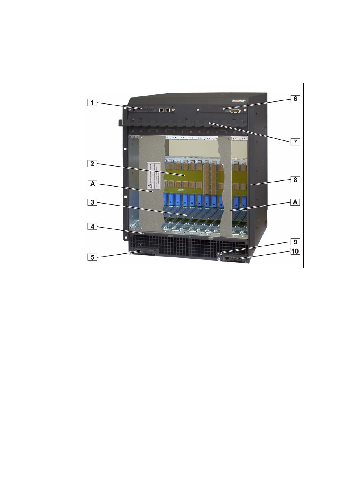
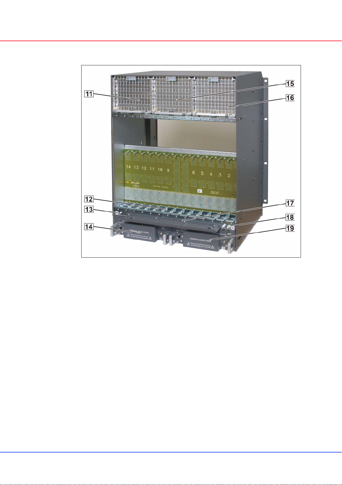
2 Shelf Overview.................................................................................................. 5
3 Shelf Installation............................................................................................. 10
3.0.1 Ensuring Overcurrent Protection.......................................................... 10
3.0.2 Ensuring Proper Airflow....................................................................... 10
3.0.3 Creating a Safe Environment............................................................... 10
3.1 Unpacking.......................................................................................................... 11
3.2 Rack-Mounting................................................................................................... 12
3.3 Mounting Bracket Swap..................................................................................... 14
3.4 Additional Rear Fixing Points............................................................................. 15
3.5 Shelf Ground Connection .................................................................................. 16
3.5.1 Specification for the Shelf Ground connection cable........................... 16
3.6 Shelf Power Connection.................................................................................... 17
3.7 Specification for the power connection cables................................................... 17
3.8 Installation the power connection cables........................................................... 18
3.9 Initial Operation.................................................................................................. 19
3.10 Logic Ground to Shelf Ground connection......................................................... 20
4 Maintenace...................................................................................................... 21
4.1 Accessing the Shelf Management Software...................................................... 21
4.1.1 Command Line Interface (CLI)............................................................. 21
4.1.2 Basic CLI Commands.......................................................................... 22
4.2 Telco Alarms...................................................................................................... 23
4.2.1 Telco Alarm Interface........................................................................... 23
4.2.2 Telco Alarm LEDs................................................................................ 23
4.2.3 Alarm Silence Push Button.................................................................. 23
4.2.4 Alarm Reset......................................................................................... 23
4.3 Air Filter Replacement....................................................................................... 24
4.4 Power Entry Module (PEM) Replacement......................................................... 25
4.4.1 PEM Fuse Replacement...................................................................... 28
4.5 Fan Tray Replacement...................................................................................... 29
4.6 Shelf Alarm Display (SAD) Replacement .......................................................... 30

14-Slot AdvancedTCA Shelf
11596-100/-101/-102/-103
www.a-tca.com / www.schroff.biz II R1.1, July 23, 2008
4.7 Shelf Alarm Panel (SAP) Replacement............................................................. 31
4.8 Chassis Data Module (CDM) Replacement....................................................... 31
4.9 Shelf Manager Replacement............................................................................. 33
4.10 ShMM-500 Replacement................................................................................... 34
4.11 Insertion of ATCA Boards.................................................................................. 35
4.12 Part Numbers..................................................................................................... 36

14-Slot AdvancedTCA Shelf Safety
11596-100/-101/-102/-103
www.a-tca.com / www.schroff.biz 1 R1.1, July 23, 2008
1 Safety
The intended audience of this Service Manual is system integrators and
qualified service personnel.
The instructions in this manual primarily describe the installation and
maintenance of the 14-Slot ATCA Shelf.
When installing racks, electrical wiring and other equipment, you should
follow all local, state, federal, or international codes and regulations.
1.1 Safety Symbols used in this document
1.2 General Safety Precautions
• Service personnel must know the necessary electrical safety, wiring and
connection practices for installing this equipment in a telecommunication
environment.
• Install this equipment only in compliance with local and national electrical
codes.
• For additional information about this equipment, see the PICMG 3.0
Specification (www.picmg.com) or the User’s Manual.
Hazardous voltage!
This is the electrical hazard symbol. It indicates that there are dangerous
voltages inside the Shelf.
Caution!
This is the user caution symbol. It indicates a condition where damage of the
equipment or injury of the service personnel could occur. To reduce the risk of
damage or injury, follow all steps or procedures as instructed.
Danger of electrostatic discharge!
TheShelfcontainsstaticsensitivedevices.Topreventstaticdamageyoumust
wear an ESD wrist strap.
Warning!
Voltages over 60 VDC can be present in this equipment. As defined in the
PICMG 3.0 Specification, this equipment is intended to be accessed, to be
installed and maintained by qualified and trained service personnel only.

14-Slot AdvancedTCA Shelf Safety
11596-100/-101/-102/-103
www.a-tca.com / www.schroff.biz 2 R1.1, July 23, 2008
1.3 References and Architecture Specifications
•PICMG
®3.0 AdvancedTCA® Base Specification
(www.picmg.com)
•PICMG
®Engineering Change Notice ECN 3.0-2.0-00
• User’s Manual for the 11596-10x ATCA Shelves,
Doc-No.: 63972-172
1.4 Product Definition
The Schroff 11596-10x is a 13U / 14 Slot Shelf and designed according to
AdvancedTCA standards.
• Product Number 11596-100: Dual Star Backplane, bused IPMB
• Product Number 11596-101: Dual Star Backplane, radial IPMB
• Product Number 11596-102: Full Mesh Backplane, bused IPMB
• Product Number 11596-103: Full Mesh Backplane, radial IPMB
The Schroff 11596-10x is designed to work with two redundant
Schroff ShMM-ACB-IV Shelf Managers, at least one Shelf Manager is needed
for a working System.
• Product Number 21593-375: Shelf Manager with bused IPMB
• Product Number 21593-376: Shelf Manager with radial IPMB

14-Slot AdvancedTCA Shelf Safety
11596-100/-101/-102/-103
www.a-tca.com / www.schroff.biz 3 R1.1, July 23, 2008
1.5 ESD Wrist Strap Terminals
Two ESD Wrist Strap Terminals are located at the lower front and rear side of
the Shelf.
Figure 1: ESD Wrist Strap Terminals
Danger of electrostatic discharge!
Static electricity can harm delicate components inside the Shelf. You must
wear an ESD wrist strap before exchanging any part or electric component!
12706903
1 Front ESD Wrist Strap Terminal
(4 mm Banana Jack) 2 Rear ESD Wrist Strap Terminal
(4 mm Banana Jack)

14-Slot AdvancedTCA Shelf Safety
11596-100/-101/-102/-103
www.a-tca.com / www.schroff.biz 4 R1.1, July 23, 2008
1.6 Terms and Acronyms
Table 1: Terms and Acronyms
Term Definition
ATCA Advanced Telecom Computing Architecture
Backplane Passive circuit board providing the connectors for the front boards. Power distribution,
management and auxiliary signal connections are supported
CDM Chassis Data Module
Chassis Enclosure containing subrack, Backplane, boards, cooling devices, PEMs, same as Shelf
ECN Engineering Change Notice
ESD Electrostatic Discharge
ETSI European Telecommunications Standards Institute
FRU Field Replaceable Unit
IPMB Intelligent Platform Management Bus
IPMC Intelligent Platform Management Controller
IPMI Intelligent Platform Management Interface
PCB Printed Circuit Board
PEM Power Entry Module
RTC Real Time Clock
RTM Rear Transition Module
SAP Shelf Alarm Panel
Shelf See Chassis
ShMC Shelf Management Controller, synonymous with Shelf Manager in this document
ShMM Shelf Management Mezzanine Module
VRTN Voltage Return

14-Slot AdvancedTCA Shelf Shelf Overview
11596-100/-101/-102/-103
www.a-tca.com / www.schroff.biz 5 R1.1, July 23, 2008
2 Shelf Overview
Figure 2: Shelf Front View
12706961
1 Shelf Alarm Display (SAD) 6 Shelf Alarm Panel (SAP)
2 ATCA 14-Slot Backplane 7 Front Cable Tray
3 Front Card Cage 8 Removable Mounting Bracket
4 Air Filter 9 ESD Wrist Strap Terminal
5 Shelf Manger 1 (left) 10 Shelf Manager 2 (right)
A Transportation Lock

14-Slot AdvancedTCA Shelf Shelf Overview
11596-100/-101/-102/-103
www.a-tca.com / www.schroff.biz 6 R1.1, July 23, 2008
Figure 3: Shelf Rear View
12706887
11 Fan Tray #2 16 Fan Tray #0
12 Rear Card Cage 17 Rear Cable Tray
13 ESD Wrist Strap Terminal 18 Shelf Ground Terminal (M6 studs)
14 Power Entry Module B (PEM B) 19 Power Entry Module A (PEM A)
15 Fan Tray #1

14-Slot AdvancedTCA Shelf Shelf Overview
11596-100/-101/-102/-103
www.a-tca.com / www.schroff.biz 7 R1.1, July 23, 2008
Figure 4: Shelf mechanical dimensions, front view
All dimensions are in millimeters (mm).
12706905

14-Slot AdvancedTCA Shelf Shelf Overview
11596-100/-101/-102/-103
www.a-tca.com / www.schroff.biz 8 R1.1, July 23, 2008
Figure 5: Shelf mechanical dimensions, side view
All dimensions are in millimeters (mm).
12706906

14-Slot AdvancedTCA Shelf Shelf Overview
11596-100/-101/-102/-103
www.a-tca.com / www.schroff.biz 9 R1.1, July 23, 2008
Table 2: Technical Data
Physical Dimensions
Height 571.6 mm
Width 482.6 mm
Depth 506.54 mm (with cable trays)
Weight
Shipping weight completely assembled
with packaging 45 Kg
Shelf weight (w/o fan tray and w/o PEMs) 19 Kg
Shelf weight completely assembled 30.6 Kg
Power
Input voltage nominal -48/-60 VDC
Input voltage range -40.5 VDC …. -72 VDC
Input Power 25 A per power feed (total 4 + 4 power
feeds)
Overcurrent Protection 30 A Fuses on PEM
Cooling Capacity
Front Boards 200W / Board
RTM 15W / Board
Environmental
Ambient temperature normal operating +5°C…+45°C (41°F to 113°F)
Ambient temperature transient operating +5°C…+55°C (41°F to 131°F)
Humidity +5%...+85%, no condensation
EMI
Conducted Emissions EN 55022 Class B
Radiated Emissions EN 55022 Class B
Safety
Protected Earth Test EN 60950-1, test current 25 A,
resistance <100mOhm
Hipot Test EN 60950-1, 1000 V

14-Slot AdvancedTCA Shelf Shelf Installation
11596-100/-101/-102/-103
www.a-tca.com / www.schroff.biz 10 R1.1, July 23, 2008
3 Shelf Installation
Install the system in a restricted access area, where access can be gained only
by service personnel through the use of a special tool, lock and key, or other
means of security.
Choose a site with a dry, clean, well-ventilated and air-conditioned area that
maintains an ambient temperature of 5°C to 45°C (41°F to 113°F).
3.0.1 Ensuring Overcurrent Protection
The system relies on the protective devices in the building installation for
protection against short-circuit, overcurrent, and earth (grounding) fault. Ensure
that the protective devices in the building installation are properly rated to
protect the system, and that they comply with national and local codes.
3.0.2 Ensuring Proper Airflow
• Install the system in an open rack whenever possible. If installation in an
enclosed rack is unavoidable, ensure that the rack has adequate ventilation.
• Maintain ambient airflow to ensure normal operation. If the airflow is blocked
or restricted, or if the intake air is too warm, an over temperature condition
can occur.
• Ensure that cables from other equipment do not obstruct the airflow through
the Shelf.
• Use filler panels to cover all empty chassis slots. The filler panel prevents
fan air from escaping out of the front of an open slot.
3.0.3 Creating a Safe Environment
• Keep tools and chassis components off the floor and away from foot traffic.
• Clear the area of possible hazards, such as moist floors, ungrounded power
extension cables, and missing safety grounds.
• Keep the area around the chassis free from dust and foreign conductive
material.
Caution!
To maintain proper airflow, all open slots must be covered with filler panels.
The filler panel should include an airflow baffle that extends to backplane.

14-Slot AdvancedTCA Shelf Shelf Installation
11596-100/-101/-102/-103
www.a-tca.com / www.schroff.biz 11 R1.1, July 23, 2008
3.1 Unpacking
Consider the following when unpacking and storing the Shelf:
• Leave the Shelf packed until it is needed for immediate installation.
• After unpacking the Shelf, save and store the packaging material in case the
Shelf must be returned.
• If the packaging is damaged and possible Shelf damage is present, report to
the shipper and analyze the damage.
Caution!
When opening the shipping carton, use caution to avoid damaging the Shelf.
Danger of electrostatic discharge!
The Shelf contains static sensitive devices. While unpacking and handling the
Shelf you must wear an ESD wrist strap to prevent static damage.
Caution!
Do NOT use the Fan Tray and PEM handles or cable trays as lifting points.

14-Slot AdvancedTCA Shelf Shelf Installation
11596-100/-101/-102/-103
www.a-tca.com / www.schroff.biz 12 R1.1, July 23, 2008
3.2 Rack-Mounting
This ATCA 14-slot Shelf can be installed in 19“ equipment racks. The rack must
be accessible from the front and rear for equipment installation.
Mounting brackets and cable trays come with the system. Allow sufficient
clearance around the rack for system maintenance.
Warning!
Do NOT move the Shelf by yourself. Due to the height and weight of the Shelf,
at least two persons are needed to accomplish this task. We recommend to
use a mechanical lift or remove all hot-swappable equipment for weight
reduction.
Warning!
Do NOT stack the Shelf on top of any other equipment. If the Shelf falls, it can
cause severe bodily injury and damage the equipment.
Caution!
Do NOT remove the Transportation Locks (See Fig. 1) before the Shelf is
completely fixed in the rack.
Caution!
Do NOT use the Fan Tray and PEM handles or cable trays as lifting points.
Danger of electrostatic discharge!
The Shelf contains static sensitive devices. While handling the Shelf you must
wear an ESD wrist strap to prevent static damage.

14-Slot AdvancedTCA Shelf Shelf Installation
11596-100/-101/-102/-103
www.a-tca.com / www.schroff.biz 13 R1.1, July 23, 2008
Mounting Instructions:
• Ensure that the rack is constructed to support the weight and dimensions of
the Shelf.
• Install any stabilizers that came with your equipment rack before mounting
or servicing the system in the rack.
• Load the rack from the bottom to the top, with the heaviest system at the
bottom, avoid uneven mechanical loading of the rack.
Figure 6: Chassis-Support Brackets
.
Caution!
Never fix the Shelf only with the mounting brackets! Due to the weight of the
Shelf you must use two chassis-support brackets or a rack mount tray.
12706858
3 Chassis-Support Brackets

14-Slot AdvancedTCA Shelf Shelf Installation
11596-100/-101/-102/-103
www.a-tca.com / www.schroff.biz 14 R1.1, July 23, 2008
3.3 Mounting Bracket Swap
Figure 7: Removable Mounting Brackets
You can swap the mounting brackets (1) from position (A) to (B).
Mounting brackets swap:
1 Unscrew the locking screws (2).
2 Push the mounting bracket downwards to disengage the locking.
3 Turn the mounting bracket at 180° and move it to the new position.
4 Push the mounting bracket upwards to engage the locking.
5 Tighten the locking screws.
12706857

14-Slot AdvancedTCA Shelf Shelf Installation
11596-100/-101/-102/-103
www.a-tca.com / www.schroff.biz 15 R1.1, July 23, 2008
3.4 Additional Rear Fixing Points
The Shelf provides two additional rear fixing points. These points can be used
to enhance the shock and vibration stability.
Figure 8: Rear Mounting Brackets
Figure 9: Rear Fixing Points
Because the rear fixing points are not standardized, the respective mounting
brackets must be manufactured by the customer.
12708854
12708855

14-Slot AdvancedTCA Shelf Shelf Installation
11596-100/-101/-102/-103
www.a-tca.com / www.schroff.biz 16 R1.1, July 23, 2008
3.5 Shelf Ground Connection
The Shelf must be properly grounded via the Shelf Ground Terminal.
The location of the Shelf Ground Terminal is shown in Figure 10.
Figure 10: Shelf ground terminal
Torque for Nuts M6: 5.1 Nm (45 in.-lb.)
3.5.1 Specification for the Shelf Ground connection cable
Required wire size: AWG6
Required terminals: Use only double lug terminals with 45° angle tongue.
Example for terminal:
PANDUIT part no. LCD6-14AH-L, or Thomas&Betts part no. 54205UF
See catalogs at www.panduit.com and www.tnb.com.
Warning!
This Shelf is intended to be grounded. Ensure that the Shelf Ground terminals
are connected to Protective Earth (PE) of the building.
Danger of electrostatic discharge!
Static electricity can harm delicate components inside the Shelf. You must
wear an ESD wrist strap before exchanging any part or electric component!
12706892
1 Shelf Ground Terminal 2 PEM A
This manual suits for next models
3
Table of contents
Other Pentair Industrial Electrical manuals
Popular Industrial Electrical manuals by other brands

Murata
Murata GRM0335C1ER80WA01 Series Reference sheet

Murata
Murata GRM188R61H102KA01 Series Reference sheet

Eaton
Eaton XTCE040D Series Instruction leaflet

Murata
Murata GJM0335C1E3R8BB01 Series Reference sheet

Murata
Murata GRM0335C1H1R7BA01 Series Reference sheet

Murata
Murata GRM185R60J105KE26 Series Reference sheet

Hennlich
Hennlich HBS Instruction and maintenance manual

Murata
Murata GRM1555C1H180FA01 Series Reference sheet

Command access
Command access PD10-UL-M-KIT Insert Instructions

Siemens
Siemens 3RV1952-1E Series operating instructions

Murata
Murata GRJ216R72A102KE01 Series Reference sheet

Eaton
Eaton Crouse-Hinds Megablock F300 Series instruction manual