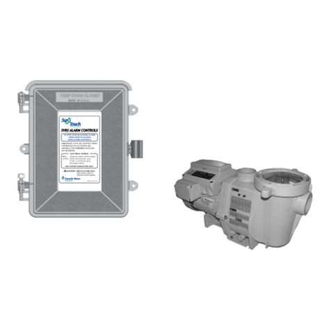
Pentair Myers PA-1 Manual

NOTE! To the installer: Please make sure you provide this manual to the owner of the equipment or to the responsible
party who maintains the system.
MODELS PA-1 and PA-2
ALARM PANELS
INSTALLATION AND SERVICE MANUAL
PA-1 (FOR 115V, 1PH SERVICE) and PA-2 (FOR 230V, 1PH SERVICE)
Part # 23833A165 | © 2012 Pentair Pump Group, Inc. | 11/08/12

9 7
/16
6
5
/16 DIA.
10 3
/411 5
/8
4 1
/4
23833A165 11/08/12 2
APPLICATION
This panel is to be used as an alarm and pump
disconnect.
ENCLOSURE
The enclosure is a NEMA 4X fiberglass that may
be
mounted inside or outside. Mounting feet are
supplied on the exterior of the box. A hinged door
with stainless steel lockable hasps is supplied.
LIGHT
The alarm light is a 15 watt, high intensity light
enclosed by a red acrylic globe. The light bulb is
a medium base appliance bulb that may be easily
removed from inside the enclosure.
CIRCUIT BREAKER
A 20 amp single pole circuit breaker is supplied
with the panel for 115V service. A 20 amp double
pole circuit breaker is supplied with the panel
for 230V service. The circuit breaker provides a
convenient method of disconnecting the power to
the pump and alarm for maintenance or service.
TERMINAL BLOCKS
Box clamp terminal blocks are provided for
connect
ing both pump and high water alarm
float leads.
FUSE
A 1 amp fuse is supplied for alarm circuit protection.
WARNING:
Do not attempt to wire this control box unless you
have a good working knowledge of electricity and
are familiar with state and local codes. If you are in
doubt about anything, contact an electrician.
The power supply for the control box will vary
depending upon which particular model you have
purchased. Do not attempt to operate this unit
on any other voltage or power distribution other
than for which it was originally designed. Failure
to comply with this will result in the immediate
cancellation of all warranties and claims.
CALIFORNIA PROPOSITION 65 WARNING:
This product and related
accessories contain chemicals known to the
State of California to cause cancer, birth
defects or other reproductive harm.
INSTALLATION
1. Select a convenient location and mount the
alarm enclosure on a stable vertical support by
means of the four mounting holes in the
mounting feet on the back of the enclosure.
2. Connect incoming power to the circuit breaker
(top lugs) and neutral terminal block. All
necessary ground wires should be connected to
the ground lug at the bottom of the panel. The
ground lug should be fastened to a good driven
earth ground by one of the methods described in
the National Electric Code.
3. Run wires from the pump and connect to
terminals 1 and 2.
4. Run wires from high water alarm float and
connect to terminals 3 and 4.
5. You may test the alarm circuit by manually
activating the float switch or by pushing the test
switch on the outside of the enclosure.
6. The enclosure may be locked by inserting a
padlock (not supplied) through either of the
enclosure hasps.

ENCLOSURE
(21981C133A)
ALARM LIGHT
(22002A002)
CIRCUIT BREAKER
(21985A014)
WIRING
DIAGRAM
MOMENTARY PUSHBUTTON
(23330A001)
CAT. NO. PA-1
USE COPPER WIRE ONLY
GROUND LUG
(21994A001)
END SECTION (2)
(21996A000)
TERMINAL BLK. (5)
(21995A000)
BACK PANEL
(21981C111A)
RUBBER BOOT
(19773A001)
FUSE HOLDER
(21991A001)
FUSE
(20514A009)
1 AMP. 200V. ACC-1
ALARM CIRCUIT FUSE
GRD
1 2 3 4
CAT. NO. PA-2
ALARM BUZZER
(21976A002)
ENCLOSURE
(21981C133A)
ALARM LIGHT
(22002A002)
CIRCUIT BREAKER
(21985A001)
WIRING
DIAGRAM
MOMENTARY PUSHBUTTON
(23330A001)
USE COPPER WIRE ONLY
GROUND LUG
(21994A001)
END SECTION (2)
(21996A000)
TERMINAL BLK. (5)
(21995A000)
BACK PANEL
(21981C111A)
RUBBER BOOT
(19773A001)
FUSE HOLDER
(21991A001)
FUSE
(20514A009)
1 AMP. 200V. ACC-1
ALARM CIRCUIT FUSE
GRD
1 2 3 4
ALARM BUZZER
(21976A002)
23833A165 11/08/12
3

INCOMING 115V
SINGLE PHASE
NL1
20 AMP
BREAKER
BLK
NWHITE
BLK
1
2
PUMP MOTOR
1 AMP
ALARM FUSE
ALARM
TEST SWITCH
BLUE
3 4
R
BZ
OVERLOAD PROTECTION
BUILT INTO MOTOR
R - ALARM LIGHT (RED)
BZ - ALARM BUZZER
HIGH WATER
ALARM FLOAT
4
3
12 GCONNECT GROUND LUG TO
A GOOD EARTH GROUND
NOTE: CONNECT GREEN WIRES
TO GROUND LUG
HIGH WATER
POWER CORD
BLK
BLK
WH
WH
CAT. NO. PA-1
115 VOLT, 1 PHASE
CAT. NO. PA-2
230 VOLT, 1 PHASE
INCOMING 115V
SINGLE PHASE
L1 L2
20 AMP
BREAKER
BLK
BLK
1
2
PUMP MOTOR
1 AMP
ALARM FUSE
ALARM
TEST SWITCH
BLUE
34
R
BZ
OVERLOAD PROTECTION
BUILT INTO MOTOR
R - ALARM LIGHT (RED)
BZ - ALARM BUZZER
HIGH WATER
ALARM FLOAT
4
3
12 GCONNECT GROUND LUG TO
A GOOD EARTH GROUND
NOTE: CONNECT GREEN WIRES
TO GROUND LUG
HIGH
WATER
POWER CORD
BLK
BLK
WH
WH
BLK
N
WH/RED
WH/RED
WH
WH/RED
WH/RED
WH
WH
23833A165 11/08/12 4

INCOMING 115V
SINGLE PHASE
NL1
20 AMP
BREAKER
BLK
NWHITE
BLK
1
2
PUMP MOTOR
1 AMP
ALARM FUSE
SILENCE
SWITCH
BLUE 34
R
BZ
OVERLOAD PROTECTION
BUILT INTO MOTOR
R - ALARM LIGHT (RED)
BZ - ALARM BUZZER
HIGH WATER
ALARM FLOAT
4
3
12
GCONNECT GROUND LUG TO
A GOOD EARTH GROUND
NOTE: CONNECT GREEN WIRES
TO GROUND LUG
HIGH WATER
POWER CORD
BLK
BLK
WH
WH
CAT. NO. PA-1S
115 VOLT, 1 PHASE
WH/RED
WH/RED
WH
GRAY
R I
R I
14 13
RI
R
VIOLET RI - SILENCE RELAY
ENCLOSURE
(21981C133A)
ALARM LIGHT
(22002A002)
CIRCUIT BREAKER
(21985A014)
WIRING
DIAGRAM
MOMENTARY PUSHBUTTON
(23330A001)
USE COPPER WIRE ONLY
GROUND LUG
(21994A001)
END SECTION (2)
(21996A000)
TERMINAL BLK. (5)
(21995A000)
BACK PANEL
(21981C134A)
RUBBER BOOT
(19773A001)
FUSE HOLDER
(21991A001)
FUSE
(20514A009)
1 AMP. 200V. ACC-1
ALARM CIRCUIT FUSE
GRD
1 2 3 4
RELAY SOCKET
(23527A002)
SILENCE RELAY
(23634A005)
ALARM BUZZER
(21976A002)
23833A165 11/08/12
5

THIS PAGE INTENTIONALLY LEFT BLANK

THIS PAGE INTENTIONALLY LEFT BLANK

Warranty Rev. 12/13
STANDARD LIMITED WARRANTY
Pentair Myers® warrants its products against defects in material and workmanship for a period of 12 months from the
date of shipment from Pentair Myers or 18 months from the manufacturing date, whichever occurs first – provided
that such products are used in compliance with the requirements of the Pentair Myers catalog and technical manuals
for use in pumping raw sewage, municipal wastewater or similar, abrasive-free, noncorrosive liquids.
During the warranty period and subject to the conditions set forth, Pentair Myers, at its discretion, will repair or
replace to the original user, the parts that prove defective in materials and workmanship. Pentair Myers reserves the
right to change or improve its products or any portions thereof without being obligated to provide such a change or
improvement for prior sold and/or shipped units.
Start-up reports and electrical schematics may be required to support warranty claims. Submit at the time of start-
up through the Pentair Myers website: http://forms.pentairliterature.com/startupform/startupform.asp?type=m.
Warranty is effective only if Pentair Myers authorized control panels are used. All seal fail and heat sensing devices
must be hooked up, functional and monitored or this warranty will be void. Pentair Myers will cover only the lower
seal and labor thereof for all dual seal pumps. Under no circumstance will Pentair Myers be responsible for the cost
of field labor, travel expenses, rented equipment, removal/reinstallation costs or freight expenses to and from the
factory or an authorized Pentair Myers service facility.
This limited warranty will not apply: (a) to defects or malfunctions resulting from failure to properly install, operate or
maintain the unit in accordance with the printed instructions provided; (b) to failures resulting from abuse, accident
or negligence; (c) to normal maintenance services and parts used in connection with such service; (d) to units that
are not installed in accordance with applicable local codes, ordinances and good trade practices; (e) if the unit is
moved from its original installation location; (f) if unit is used for purposes other than for what it is designed and
manufactured; (g) to any unit that has been repaired or altered by anyone other than Pentair Myers or an authorized
Pentair Myers service provider; (h) to any unit that has been repaired using non factory specified/OEM parts.
Warranty Exclusions: PENTAIR MYERS MAKES NO EXPRESS OR IMPLIED WARRANTIES THAT EXTEND BEYOND
THE DESCRIPTION ON THE FACE HEREOF. PENTAIR MYERS SPECIFICALLY DISCLAIMS THE IMPLIED WARRANTIES
OF MERCHANTABILITY AND FITNESS FOR ANY PARTICULAR PURPOSE.
Liability Limitation: IN NO EVENT SHALL PENTAIR MYERS BE LIABLE OR RESPONSIBLE FOR CONSEQUENTIAL,
INCIDENTAL OR SPECIAL DAMAGES RESULTING FROM OR RELATED IN ANY MANNER TO ANY PENTAIR MYERS
PRODUCT OR PARTS THEREOF. PERSONAL INJURY AND/OR PROPERTY DAMAGE MAY RESULT FROM IMPROPER
INSTALLATION. PENTAIR MYERS DISCLAIMS ALL LIABILITY, INCLUDING LIABILITY UNDER THIS WARRANTY, FOR
IMPROPER INSTALLATION. PENTAIR MYERS RECOMMENDS INSTALLATION BY PROFESSIONALS.
Some states do not permit some or all of the above warranty limitations or the exclusion or limitation of incidental or
consequential damages and therefore such limitations may not apply to you. No warranties or representations at any
time made by any representatives of Pentair Myers shall vary or expand the provision hereof.
1101 MYERS PARKWAY 490 PINEBUSH ROAD, UNIT 4
ASHLAND, OHIO 44805 CAMBRIDGE, ONTARIO, CANADA N1T 0A5
PH: 855-274-8947 PH: 800-363-7867
WWW.FEMYERS.COM WWW.FEMYERS.COM
This manual suits for next models
1
Table of contents
Other Pentair Security System manuals