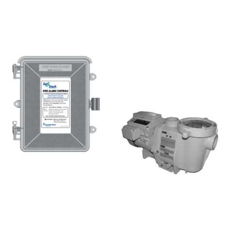
Pentair Pentek Defender User manual

NOTE! To the installer: Please make sure you provide this manual to the owner of the equipment or to the responsible
party who maintains the system.
INSTALLATION AND USER’S GUIDE
PENTEK DEFENDER
ENGLISH: PAGES 2-9
Installation/Operation/Parts
For further operating, installation,
or maintenance assistance,
call 1-800-628-9439
PN1053 (08/21/18) | © 2018 Pentair plc
Model
CSC-LINK
PENTEK
293 WRIGHT STREET, DELAVAN, WI 53115
888.782.7483 • WWW.STA-RITE.COM

Safety 2
READ AND FOLLOW
SAFETY INSTRUCTIONS!
This is the safety alert symbol. When you see this
symbol on your pump or in this manual, look for one of
the following signal words and be alert to the potential
for personal injury:
warns about hazards that will cause serious
personal injury, death or major property damage if
ignored.
warns about hazards that can cause serious
personal injury, death or major property damage if
ignored.
warns about hazards that will or can cause
minor personal injury or property damage if ignored.
The label NOTICE indicates special instructions which are
important but not related to hazards.
Carefully read and follow all safety instructions in this
manual and on pump.
Keep safety labels in good condition.
Replace missing or damaged safety labels.
Make workshops childproof; use padlocks and master
switches; remove keys.
Read carefully the product installation &
operation instructions. Failure to follow the instructions
and warnings in the manual may result. Failure to follow
the instructions and warnings in the manual may result
in serious or fatal injury and/or property damage, and
will void the product warranty. This product must be
installed by a qualified professional. Follow all applicable
local and state codes and regulations. In the absense of
such codes, follow the current editions of the National
Plumbing Code and National Electric Code, as applicable.
This product is used in conjunction with
a system containing a tank under pressure, which may
over time corrode, weaken and burst or explode, causing
serious or fatal personal injury, leaking or flooding
and/or property damage. To minimize risk, a licensed
professional must install and periodically inspect and
service the product and system. A drip pan connected to
an adequate drain must be installed if leaking or flooding
could cause property damage. Do not locate system in
an area where leaking could cause property damage.
This control is capable of running pumps
to pressures that may exceed the limitations of system
components. Never set the operating pressure higher
than that of the safe system capacity.
This control can be adjusted to a narrow
pressure differential. An improperly sized tank can cause
the pump to cycle and lead to pump damage. This may
require a larger pressure tank than is normally used.
California Proposition 65 Warning
This product and related accessories
contain chemicals known to the State of California to
cause cancer, birth defects or other reproductive harm.
ELECTRICAL SAFETY
ELECTROCUTION HAZARD. Must be
installed by a qualified professional. First disconnect
all electrical power before attempting service. For
your safety, the installation and operation instructions
must be followed to minimize the risk of electric shock,
property damage or personal injury.
GENERAL SAFETY
Do not touch an operating motor. Modern
motors can operate at high temperatures. To avoid burns
when servicing pump, allow it to cool for 20 minutes after
shut-down before handling.
Do not allow pump or any system component to freeze.
To do so will void warranty.
Pump only water with this pump.
Periodically inspect pump and system components.
Wear safety glasses at all times when working on pumps.
Keep work area clean, uncluttered and properly lighted;
store all unused tools and equipment.
Keep visitors at a safe distance from the work areas.
Pump body may explode if used as a
booster pump unless relief valve capable of passing
full pump flow at 75 psi is installed.
A water test must be taken before
installation of any water treatment equipment. The
water quality can significantly influence the life of your
system. You should test for corrosive elements, acidity,
total solids and other relevant contaminants, including
chlorine and treat your water appropriately to insure
satisfactory performance and prevent premature failure.
Use only lead-free solder and ux for all
sweat-solder connections, as required by state and
federal codes.
EXPLOSION OR RUPTURE HAZARD! A relief
valve must be installed to prevent pressure in excess of
local code requirement or maximum working pressure
designated in the product manual, whichever is less.
Do not expose system to freezing temperatures or
temperatures in excess of 120°. Failure to properly size
the system or follow instructions in the manual may result
in excessive strain on the system and may lead to product
failure, leakage, ooding and/or property damage.

Installation 3
INTRODUCTION
Pentek CSC Control and Monitoring System provides
control of high voltage (120/240 VAC) pumps. Pump
operations can be controlled through a mobile device or
computer.
Techincal Specifications
Input Power 120/240V, Single Phase
Operating Current 12A Max
Frequency 50/60Hz
Enclosure Rating NEMA 3R*
Maximum System
Operating Pressure 100psi
* When watertight conduit connectors are used
LEDs
Power/Status: Indicates if the device has power or is
faulted.
Connection: Indicated the status of teh wireless
connection.
Power/Status Connection
Off There is no
power to the
unit.
Off There is no power to
the unit.
Solid
Red
There is
power to the
unit but it
has faulted.
Blinking
Blue
The unit is in local
WiFi access mode.
Solid
Green
There is
power to the
unit and it
is operating
normally.
Solid
Blue
The unit is connected
to a local phone,
tablet, or computer.
Blinking
Green
Pump is
running
Blinking
Green
The unit is connected
to the home WiFi
network.
Solid
Green
The unit is connected
to the internet.
Solid
Red
The unit is not
connected to any
WiFi and is searching
for the home
network.
Blinking
Red
The unit is scanning
for available WiFi
networks.
PRE-INSTALLATION
DANGER! EXPLOSION HAZARD. When the
well tank has been in service and a change to a higher pre-
charge pressure is necessary due to a required change in
the pressure switch setting, failure to follow instructions
below can cause a rupture or explosion, possibly causing
serious or fatal personal injury and/or property damage.
• Do not adjust or add pressure if there has been a loss
of air.
• Do not adjust the pre-charge pressure if there is
visible exterior corrosion.
• Do not adjust the pre-charge pressure if there has
been a reduction of the pump cycle time or the pre-
charge pressure compared to its initial setting. This
is because a reduction in pump cycle time can result
from loss of tank air pressure which can mean there
may be internal corrosion. Any re-pressurization
or additional pressure could result in rupture or
explosion.
• Do not use with components or materials that are
incompatible with the unit.
PLUMBING
1. The unit should be mounted as close as possible to
the pressure tank.
Locate the unit following all local codes. Do
not locate the unit where it can be affected by flooding.
2. You may assemble the unit to a “Tank Tee” or “Tank
Cross” (Figure 1) or adapt the unit to an in-line pipe
fitting (Figure 2). Use pipe sealing tape or pipe
sealant. Tighten the unit using the wrench flats
provided on the bottom connection. DO NOT EXCEED
15 LB./FT. of torque.
NOTE: Do not allow pipe sealant or other contaminants to
enter the small port in the unit connection.
NOTE: A mechanical pressure gauge is not required. Use
the appropriate plug to block any unused ports.
WIRING
Install, ground, wire and maintain device in accordance
with your local electrical code and all other codes/
ordinances that apply. Consult your local building
inspector for local code information.
Ground device permanently using wire of size and type
specified by approved local or national codes.
Risk of explosion. Do not ground to gas
supply line.
Connect ground wire first. Connect to ground first, then
to green grounding wire provided in the device. Ground
connection MUST be made to this wire. Do not connect
motor to electrical power supply until unit is permanently
grounded; otherwise serious or fatal electrical shock
hazard may be caused.

Installation 4
For best ground connection, connect to grounded lead
in service panel or to metal underground water pipe or
well casing at least 10 ft. long. If plastic pipe or insulated
fittings are used, run ground wire directly to metal well
casing or use ground electrode furnished by the power
company.
To Connect Line and Motor
Risk of electrical shock. Disconnect power
at service panel before connecting pressure switch to
pump. Do not operate pump unless motor and pressure
switch are connected to each other by a solid metal
connection and are grounded.
1. Remove device cover.
2. Connect green ground wires from both the LINE and
MOTOR wiring to the green ground wire in the device
with a wire nut of size and type specified by approved
local or national codes. See Figure 1 and Table 1.
3. Using the included wires and wire nuts of size and
type specified by approved local or NEC national
codes, connect power supply leads to switch
terminals marked LINE. See Figure 1 and Table 1.
4. Using the included wires and wire nuts of size and
type specified by approved local or national codes,
connect motor leads to switch terminals marked
MOTOR. See Figure 1 and Table 1.
5. Replace device cover.
6. Pentek CSC is now wired for operation.
Watertight conduit connections must be
used when exposed to direct weather, moisture or high
humidity.
COMMISSIONING
Pentek CSC requires two easy steps to commission it for
use: Online Registration and WiFi connection.
NOTE: It is important that the commissioning steps be
done in the order listed in this manual. The device may
be paired with, and controlled from, either a smartphone/
tablet or computer. The smartphone, tablet or computer
you wish to use to pair the Pentek CSC with the
homeowner’s router must be within range of the device
during the pairing processes described below.
Online Device Registration
New users can download the Link2O™ app to their
smartphone or tablet from the app store or access the
website from a computer at www.MyLink2o.com.
1. Navigate to the web page or open the app.
2. Existing users: Login to your account and click
DEVICES and then ADD NEW DEVICE.
3. New users: Click Sign Up on the web page or scroll
down on the app and click SIGNUP AS A CUSTOMER.
4. Follow prompts to enter device and system
information and complete online device registration.
NOTE: The unique device ID code is required for this step.
The ID code can be found either on the inner cover of the
device or on the front of this manual.
Motor Side
Connections
Ground
Connection
Line Side
Connections
Device Wiring
Ground
Connections
Device Ground (Green) + Motor Ground (Green) +
Line Ground (Green)
Line Side
Connections
Line (Black) + Device (Yellow)
Line (White) + Device (Yellow)
Motor Side
Connections
Motor (Black) + Device (Yellow)
Figure 1: Device Wiring
Table 1: Device Wiring

Installation 5
Pair the Pentek CSC with Smartphone/Tablet or Computer
1. Disconnect power to the Pentek CSC device for 10 seconds, and then
return power to the unit to activate local access or connection mode.
2. Wait until the Communication LED on the device is be Blinking Blue. This
step could take up to 5 minutes.
3. Open your smartphone or tablet WiFi settings.
To open WiFi Settings on smartphones or tablets:
Go to Settings>WiFi or Settings>Connections>WiFi.
To open WiFi Settings on computers: Click on the
WiFi icon [ or ] in the desktop system tray. See Figure 1.
4. Find the available network or access point titled “PPSxxxxxxx”. Select this
network or access point to connect to Pentek CSC. See Figure 2.
5. Once connected, the Communication LED on the device will change to
Solid Blue.
6. Open any web browser on your smartphone, tablet or computer.
7. Type 192.168.1.1 into the address bar and press enter. This will take you to
the pairing page.
8. Click on the Setup Tab.
9. Select the homeowner’s router from the drop down SSID list and enter the
router password into the security key field. See Figure 2.
Note: Passwords are case sensitive.
Note: If the homeowner’s router does not display in the SSID drop down
list (see Figure 2), the router may be too far from the Pentek CSC device to
receive a strong enough signal. The signal strength may be improved by:
a. Moving the router to a position that minimizes the distance and
obstructions between it and the device.
b. Repositioning the device so that the distance and obstructions between
it and the wireless router are minimized.
c. Purchasing and installing a WiFi range extender to bridge the WiFi signal
between the router and Pentek CSC device.
10. Click the Add button to save this WiFi network in the device.
11. Scroll down to CSC Settings.
a. Verify Upper and Lower Setpoints are set properly. Note: Maximum value
for the Upper Setpoint is 100psi.
b. Enter the pump motor Service Factor Amps (SFA).
Note: SFA is entered in Milliamps. For example, if SFA = 7.5A, enter 7500.
For SFA = 10A, enter 10000. Maximum value is 12A or 12000mA.
12. Click Apply. Device setup is now complete.

Installation 6
Parameter Unit of Measure
Value
Description
Default Min. Max.
Upper Pressure Setting (UPS) psi 50 10 90 Sets the pressure for when the pump stops
running. Traditionally the Cut-Out setting.
Lower Pressure Setting (LPS) psi 30 0 UPS - 1 Sets the pressure for when the pump starts
running. Traditionally the Cut-In setting.
Over Pressure psi 80 UPS + 5 100 Sets Over Pressure Fault value.
Service Factor Amps A - 0 12 Service factor amps (max. load) of motor the
device is operating.
Extended Run Time Minutes 60 1 65000 Number of minutes device can run before it
faults on Extended Runtime
Dry Run - Enabled Disabled Enabled Enables or disables Dry Run Detection
Dry Run Delay Minutes 1 65000 Time device waits to restart pump when Dry
Run is detected.
Dry Run Detection Time Seconds 30 1 65000 Time the device takes to recognize Dry Run
condition.
Pressure psi - 0 100 Displays the actual system pressure at
Rfssi?
Connect Pentek CSC to Home WiFi
1. Disconnect your smartphone/tablet or computer from the device WiFi. Open your smartphone or tablet WiFi
settings.
To open WiFi Settings on smartphones or tablets:
Go to Settings>WiFi or Settings>Connections>WiFi.
To open WiFi Settings on computers: Click on the
WiFi icon [ or ] in the desktop system tray.
2. Either select the homeowner’s WiFi network or Forget the PPSxxxxx network.
3. The Connection LED on the device will change to Blinking Green once connected to the homeowner’s WiFi network
and then turn to Solid Green when connected to the internet.
Note: If the Communication LED is Red, verify that the homeowner’s WiFi network is working properly.
Note: If the Communication LED stays Blinking Green, verify that the device is setup on the Link2O app or www.
mylink2o.com.
Parameter List

Troubleshooting 7
Solid Red
Blinking Red
Blinking Blue
Solid Blue
Blinking Green
Solid Green
The unit is indicating that it is not connected to any WiFi and is searching for the home network(s) stored in
the device during setup.
The unit is scanning for available WiFi networks. The networks found during this step populate the SSID drop
down during the setup process.
The unit is in local WiFi access mode and is ready to be connected to a phone/tablet or computer.
The unit is connected to a local phone, tablet, or computer.
The unit is connected to the home WiFi network. It will change to Solid Green when it connects to the
internet and product servers. If the device is not already registered to an account, it will stay in this mode.
The unit is connected to the internet and the product servers.

FAULT TRIGGER POSSIBLE CAUSES POSSIBLE SOLUTIONS
Over Current
The device is behaving like and
ammeter and indicating that
it is drawing greater than the
programmed SFA after initial
motor start.
Shorted motor wires - line to line
Check line to line resistance (Ohms) and
conrm they match motor specications.
(Rx1 scale)
Shorted motor wires - line to ground
Damaged wire insulation. Check motor wire
insulation with a megger. Recommend a
meter that can read values 2,000,000 Ohms
or more.
Dry run
Default setting: If the pressure
in the system drops below 10psi
for 15 seconds, the device faults.
NOTE: Dry Run is based solely
on the ability of the system to
maintain pressure. It is not based
on Amps.
Over pumping the well. Check water level in the well.
Operation at open discharge so the
transducer does not see the required
10psi of back pressure.
To operate continuously at open discharge,
lower Sensitivity (detection pressure).
Setting to 0 essentially turns Dry Run off.
To operate intermittently at open discharge,
set Detection Time to exceed the open
discharge run time.
Locked Rotor
Over Pressure
System pressure exceeded the
Over Pressure limit set in the
device.
Set point changed to be too close to
Over Pressure setting.
Recommend at least a 10psi difference
between set point and Over Pressure setting.
Water treatment installed between
device and tank causes water
hammer. As ow through the water
treatment decreases, the tank is
isolated and water hammer may
happen.
Locate device and tank before all water
treatment.
Check valve located between tank
and device. This allows pressure to
build up from thermal expansion of
hot water heater.
Remove or relocate check valve.
No tank in system causes water
hammer. Add an appropriate tank.
Waterlogged tank causes water
hammer. Check tank and replace if necessary.
Tank too small for system capacity
causes water hammer. Add an appropriate tank.
Excessive Run Time
The system ran continuously for
longer than the Ex Runtime Hours
setting.
Leak in the system. Check for leaks in pipe system.
Short Cycle The system is running for a
shorter time than it should. Waterlogged tank. Check tank and replace if necessary.
Troubleshooting 8
Fault Codes

Warranty 9
Limited Warranty
STA-RITE® warrants to the original consumer purchaser (“Purchaser” or “You”) of the products listed below, that they will be free
from defects in material and workmanship for the Warranty Period shown below.
Product Warranty Period
Water Systems Products — jet pumps, small centrifugal pumps,
submersible pumps and related accessories
whichever occurs first:
12 months from date of original installation,
or 18 months from date of manufacture
Pro-Source™ Composite Tanks 5 years from date of original installation
Pro-Source™ Steel Pressure Tanks 5 years from date of original installation
Pro-Source™ Epoxy-Lined Tanks 3 years from date of original installation
Sump/Sewage/Effluent Products 12 months from date of original installation, or
18 months from date of manufacture
Our warranty will not apply to any product that, in our sole judgement, has been subject to negligence, misapplication, improper
installation, or improper maintenance. Without limiting the foregoing, operating a three phase motor with single phase power
through a phase converter will void the warranty. Note also that three phase motors must be protected by three-leg, ambient
compensated, extra-quick trip overload relays of the recommended size or the warranty is void.
Your only remedy, and STA-RITE’s only duty, is that STA-RITE repair or replace defective products (at STA-RITE’s choice). You
must pay all labor and shipping charges associated with this warranty and must request warranty service through the installing
dealer as soon as a problem is discovered. No request for service will be accepted if received after the Warranty Period has
expired. This warranty is not transferable.
STA-RITE SHALL NOT BE LIABLE FOR ANY CONSEQUENTIAL, INCIDENTAL, OR CONTINGENT DAMAGES WHATSOEVER.
THE FOREGOING WARRANTIES ARE EXCLUSIVE AND IN LIEU OF ALL OTHER EXPRESS AND IMPLIED WARRANTIES, INCLUDING
BUT NOT LIMITED TO THE IMPLIED WARRANTIES OF MERCHANTABILITY AND FITNESS FOR A PARTICULAR PURPOSE. THE
FOREGOING WARRANTIES SHALL NOT EXTEND BEYOND THE DURATION EXPRESSLY PROVIDED HEREIN.
Some states do not allow the exclusion or limitation of incidental or consequential damages or limitations on the duration of an
implied warranty, so the above limitations or exclusions may not apply to You. This warranty gives You specific legal rights and
You may also have other rights which vary from state to state.
This Limited Warranty is effective June 1, 2011 and replaces all undated warranties and warranties dated before June 1, 2011.
STA-RITE®
293 Wright Street • Delavan, WI U.S.A. 53115
Phone: 1-888-782-7483 • Fax: 1-800-426-9446 • Web Site: sta-rite.com
This manual suits for next models
1
Table of contents
Other Pentair Security System manuals