Parabeam 700-FSK User manual

Parabeam
LONG RANGE ALERT SYSTEMS
®
INSTALLATION MANUAL
Paratronics Developments Ltd, Kapiti New Zealand
SITE CODE:

OVERVIEW
The Parabeam®700-FSK Driveway Alert System
monitors your driveway around the clock, alerting
you whenever a vehicle or person enters the property,
ensuring peace of mind and security.
POPULAR APPLICATIONS
• Security monitoring of driveways and entranceways
• Security monitoring of farms, lifestyle blocks and
residential properties
• Security monitoring of beach properties and sites
vulnerable to public access
• After-hours monitoring of sales yards, nurseries and
storage facilities and outdoor venues
• Temporary deployment; monitoring building sites
• Monitoring of fuel storage facilities
• Portable installations; monitoring civil engineering
project sites (utilising our cellular devices to receive
alerts)
• Generating a trigger/event in‘event-driven CCTV’
applications
• Generating a photoelectric beam for solar-powered
automatic gates
The Parabeam® 700-FSK Driveway Alert System utilises
a point-to-point infrared detection beam. Whenever
this beam is broken, a radio signal is immediately sent
to the Base Receiver, triggering a loud beeping sound.
The Base Receiver can be situated up to 1km away from
the Beam-set, making it the perfect solution for large
properties and long distance applications.
The maximum beam length is 40m.
The beam is created by two small Beam-units (referred
to as a Beam-set). These small units are installed
opposite each other and support the precise photo-
electric beam. This beam is not visible, but can be
imagined as being similar to a laser.
The Base Receiver can support up to two Beam-sets,
which can operate on dierent zones.
The Base Receiver has the ability to activate compatible
outdoor security lights, sirens, external beepers/pagers,
and alarm panels. Any devices (eg: lights) needing
additional timers and mains-rated switching interfaces
are not supplied by Paratronics Developments Ltd.
Alerts can also be forwarded as SMS text messages to
any mobile phone (optional extras).
BEAM SENSITIVITY
The Beam-set beam utilises a 1/6th-of-a-second beam
interruption timer to avoid false activations by birds,
falling leaves or rain, while alerting to larger objects,
including fast-moving vehicles.
ADJUSTABLE BEAM LENGTH
The length of the detection beam may be altered to suit
the installation.
On the Beam Emitter circuit board there are two pairs of
headers. See DIAGRAM 1. Fit the supplied jumpers if a
longer beam length is required.
NOTE: The default factory setting is ‘Maximum 10m’
(no jumpers) as 99% of Parabeam® systems sold are
installed to monitor driveways.
DIAGRAM 1
Beam Emitter Jumper Options
TWO-WAY CONNECTIVITY
The Parabeam® 700-FSK Driveway Alert System
introduces two-way connectivity - ensuring for a more
robust radio link. Whenever any installed Beam-set
transmits data to the Base Receiver, the Base Receiver
responds, sending out a short conrmation message. If
ever the Beam-set does not receive conrmation from
the Base Receiver, it will re-send the data. The Beam-set
will do this up to four times before‘giving up’.
Copyright 2011 Paratronics Developments Ltd, Kapiti, New ZealandParabeam® 700-FSK Installation Manual Page 2

TESTING INDOORS
Parabeam® has not been designed to be installed
indoors.
If you wish to test a Parabeam® system indoors, use a
large room and ensure the two Beam Units are placed
at least 3 metres apart. In smaller spaces the Beam-set
is dicult to test as the IR signal tends to reect o the
walls, entering the Beam Communicator from many
dierent angles.
If you are testing two Beam-sets indoors at the same
time, ensure each Beam-set is at least 10m apart to avoid
cross-talk.
3 YEAR WARRANTY
The Parabeam® 700-FSK Driveway Alert System is
supported by a 3 Year Warranty, protecting against
defects in materials and workmanship for three years.
INSTALLATION
INTRODUCING THE BEAM-SET
The Beam-set is made up of two Beam Units - a Beam
Emitter and a Beam Communicator; and two solar panels.
The Beam Emitter emits a photo-electric beam, which is
detected by the Beam Communicator. Whenever the beam
is broken, the Beam Communicator transmits a wireless RF
signal to the Base Receiver.
The maximum distance between the two Beam Units is
40m.
The Beam Communicator also sends diagnostics
information to the Base Receiver, informing of any faults or
issues with the Beam-set.
The Beam Communicator is easily identied as the unit
with the antenna protruding from it.
SELECTING SUITABLE MOUNTING
POINTS FOR THE BEAM-SET
To install the Beam-set, select two suitable mounting
points for the Beam-set and solar panels - one on either
side of the area being monitored. The Beam-set needs
to be installed so that each Beam Unit directly faces the
other.
For maximum connectivity range with the Base Receiver,
avoid installing the Beam Communicator next to metal
surfaces as these can interfere with the signal, drastically
reducing the range.
Ensure that nothing is likely to cause false activations
by interfering with the detection beam, and that low-
angle sunlight will not enter the ”eye”of the Beam
Communicator.
The optimum height for Beam-set installation is about
800mm above ground level. The Beam-set should be
high enough to avoid being activated by cats and other
animals, but low enough so that the body of a standard
automobile will pass through the beam.
MOUNTING THE BEAM-SET
Begin by taking each Beam Unit and attach one of the
smaller U shaped brackets using the supplied philips
screws and Nylok® nuts, as in DIAGRAM 2.
DIAGRAM 2
Attaching Brackets To Beam Unit
Mount the units about 800mm above ground-level
and align visually.
TIP: Use a socket set with an extender and an 8mm
socket for fastening the brackets with the supplied hex
screw fasteners.
Stretch out the black Antenna Boost wire, coiled up
on the underside of the Beam Communicator. When
stretched out it will hang straight down below the Beam
Unit.
DIAGRAM 3
Beam Units Installed
ANTENNA BOOST WIRE
Copyright 2011 Paratronics Developments Ltd, Kapiti, New ZealandParabeam® 700-FSK Installation Manual Page 3

MOUNTING THE SOLAR PANELS
Because our solar panels are treated with a UV-
blocking coating to prevent premature degradation
from sunlight, please take care when handling them.
Attach the larger U shaped brackets to the solar panels.
Mount the panels, using the supplied hex screw
fasteners.
Aim each solar panel towards the sky (DIAGRAM 4). If the
solar panels are being installed in partial shade, tilt the
panels for maximum winter sun exposure.
NOTE: Install the solar panel at least 100mm away from
the Beam Communicator antenna.
DIAGRAM 4
Installing A Solar Panel
WIRING UP THE SOLAR PANELS AND
BEAM UNITS
Remove the front covers from the Beam Units using a
at-head screwdriver.
Plug the battery connectors into the small white
connectors on each Beam Unit circuit board. Note that
the connector can only be inserted one way.
ENSURE THAT THE BATTERIES ARE SEATED FLAT ON
THE LEDGES OF THE ENCLOSURE, OR THEY WILL
BLOCK THE BEAM.
Cut the wires to the correct length on each solar panel.
Strip solar panel wires (as shown in DIAGRAM 5).
DIAGRAM 5
Preparing Solar Panel Wire
Feed a solar panel cable through the black cable gland
on the underside of each Beam Unit.
Connect the black and red wires to the correct terminals
inside each enclosure (DIAGRAM 6) and tighten each of
the two screws with a small at-head screwdriver.
DIAGRAM 6
Connecting The Solar Panel Wires Inside the Beam Units
Arrange the internal wires so they sit clear of the IR
beam window on the front covers. See DIAGRAM 7.
DIAGRAM 7
Beam Unit Wiring
Gently tighten the large plastic nut on the cable gland to
seal the Beam Unit and to relieve pressure on the cable;
avoiding stress on delicate circuit board.
Checking rst that the solar panel wires are well away
from the beam windows, re-attach the front covers on
both Beam Units, making sure that the correct cover is
attached to each Unit. See DIAGRAM 8.
IMPORTANT: THE FRONT COVERS ON THE TWO BEAM
UNITS ARE NOT INTERCHANGEABLE.
The Beam Communicator front cover has a small round
window above the main rectangular window.
BEAM EMITTER BEAM COMMUNICATOR
Copyright 2011 Paratronics Developments Ltd, Kapiti, New ZealandParabeam® 700-FSK Installation Manual Page 4

DIAGRAM 8
Beam Unit Front Covers
Fasten the cables using the nail-in clips provided.
INTRODUCING THE BASE RECEIVER
The Base Receiver receives alerts from any installed Beam-
set, whenever a beam is broken. The Base Receiver also
receives diagnostic messages from the installed Beam-
set(s), including Low Battery and Beam Blocked alerts.
The Two-zone Base Receiver supports up to two Beam-sets.
Each Beam-set activates a dierent beeping sequence from
the Base Receiver so it maybe easity identied.
Whenever the Base Receiver receives communication
of any kind from the Beam-Set, it responds with
an acknowledgment / conrmation signal. See
‘COMMUNICATOR AMBER LIGHT INDICATIONS’for more
information.
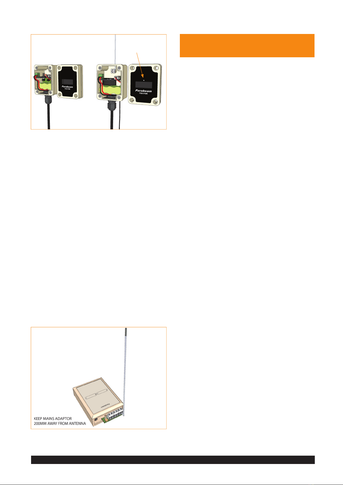
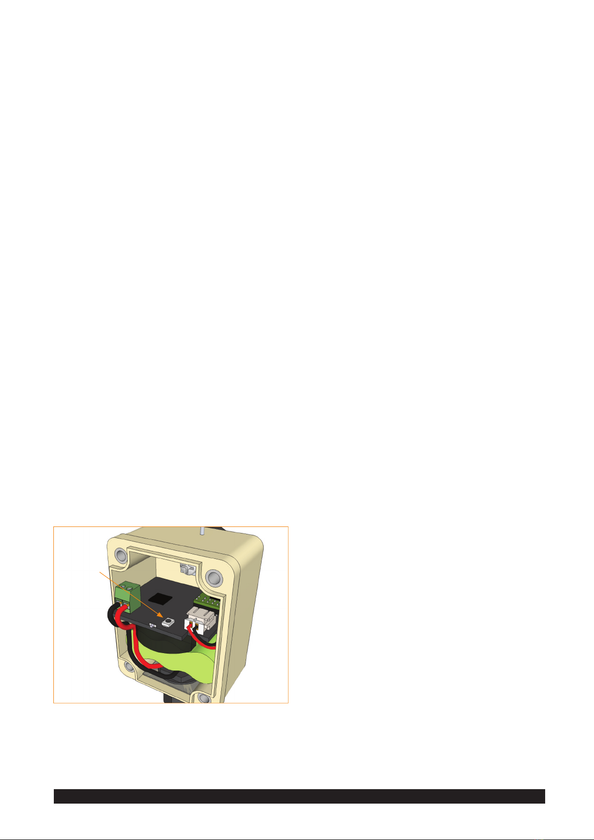
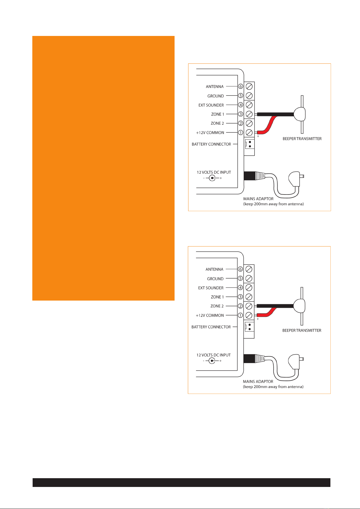
INSTALLING THE BASE RECEIVER
Fasten the antenna to base receiver - noting the correct
terminal (DIAGRAM 9). Connect power.
DIAGRAM 9
Installing the Supplied Antenna
SMALL ROUND WINDOW
BEAM EMITTER BEAM COMMUNICATOR
TIP: Locate the Base Receiver away from cordless
telephones and any device that may radiate
interference. This includes the supplied plug pack.
BEAM RESET TIMES
Whenever the beam is activated, it takes 8 seconds for
it to reset itself - from the last beam interruption. If
two objects break the beam in less than 8 seconds of
one another, the Base Receiver will only sound an alert
for the rst object. The 8 second reset countdown will
begin once the second object has passed through the
beam.
If the beam is interrupted within the 8 second time
frame for more than 20 continuous seconds, the Base
Receiver will show Beam Blocked (a solid amber light).
Once the beam has been cleared for at least 8 seconds,
the Base Receiver will again show Enrolled and Operating
Normally (a solid green light).
For example; a moving tree branch interrupting the
beam every few seconds will stop the beam from
resetting, causing a Beam Blocked indication to appear
on the Base Receiver.
BEAM COMMUNICATOR AMBER LIGHT
INDICATIONS
Whenever the Beam-set is activated the Beam
Communicator amber LED light will ash twice
(within half a second) - once to indicate the outgoing
transmission, and once to indicate an acknowledgement
/ conrmation signal from the Base Receiver.
If the Beam-set is activated and the amber LED light
ashes steadily up to four times, it has not received an
acknowledgement / conrmation signal from the Base
Receiver. If this happens the Beam Communicator and
Base Receiver are not communcating with one another.
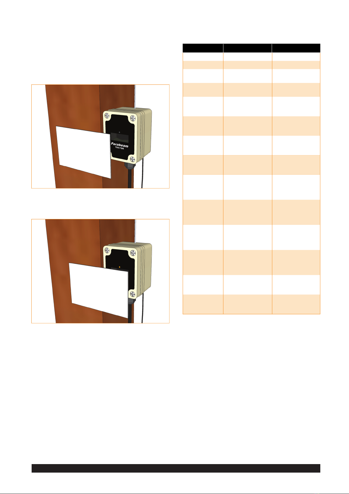
BEAM-SET ALIGNMENT
Ensure base Receiver is installed and powered-up.
Check the alignment of the Beam Units by gradually
blocking o the Beam Communicator window with thick
card. See DIAGRAMS 10 & 11.
Slide the card across the window slowly, rst from left
to right. As the card covers the window you will see the
amber light of the beam communicator quickly blink
twice. Only a small portion (one or two millimeters) of
window should be still exposed when the amber light
blinks twice. This means the IR beam is strong.
Let the beam communicator reset by removing the card
for at least 8 seconds.
Now repeat the test, this time sliding the card across
from left to right. Again, only a small portion of window
should be still exposed when the amber light blinks
twice. If needed, adjust the brackets on both beam units
to achieve this result.
Copyright 2011 Paratronics Developments Ltd, Kapiti, New ZealandParabeam® 700-FSK Installation Manual Page 5

NOTE: If this procedure is not done you may experience
regular false activations.
If you do not observe the amber light quickly blink twice
whenever the beam communicator is activated and
instead observe it blink slowly four times, it means it is
not communicating with the base receiver.
DIAGRAM 10
Beam-Set Alignment - Step 1
DIAGRAM 11
Beam-Set Alignment - Step 2
BASE RECEIVER ALERTS | DIAGNOSTICS
The Base Receiver receives a number of messages and
alerts from the installed Beam-sets. The table below lists
all messages and alerts.
BASE RECEIVER MESSAGES & ALERTS
SOUND INDICATOR LIGHT MESSAGE / ALERT
None Zone 1 no light Zone 1 not enrolled
None Zone 2 no light Zone 2 not enrolled
None Zone 1 light solid
green
Zone 1 enrolled and
operating normally
None Zone 2 light solid
green
Zone 2 enrolled and
operating normally
1 long beep,
1 short beep;
repeated once
Zone 1 light blinking
green (for 20 seconds)
Zone 1 activated. The
Zone 1 Beam-set has
been triggered
1 long beep,
2 short beeps;
repeated once
Zone 2 light blinking
green (for 20 seconds)
Zone 2 activated. The
Zone 1 Beam-set has
been triggered
3 short beeps,
spaced nine
seconds apart
Zone 1 light solid
amber (continuous)
Zone 1 beam is
blocked. Something is
blocking the beam
3 short beeps,
spaced nine
seconds apart
Zone 2 light solid
amber (continuous)
Zone 2 beam is
blocked. Something is
blocking the beam
3 short beeps,
spaced nine
seconds apart
Zone 1 light blinking
amber (continuous)
Zone 1 no connectiv-
ity; not receiving a
signal from the Zone
1 Beam-set
3 short beeps,
spaced nine
seconds apart
Zone 2 light blinking
amber (continuous)
Zone 2 no connectiv-
ity; not receiving a
signal from the Zone
2 Beam-set
3 short beeps,
spaced nine
seconds apart
Zone 1 light solid red
(continuous)
Zone 1 Beam Com-
municator (side with
antenna) battery is
low
3 short beeps,
spaced nine
seconds apart
Zone 2 light solid red
(continuous)
Zone 2 Beam Com-
municator (side with
antenna) battery is
low
3 short beeps,
spaced nine
seconds apart
Zone 1 light blinking
red (continuous)
Zone 1 Beam Emitter
battery is low
3 short beeps,
spaced nine
seconds apart
Zone 2 light blinking
red (continuous)
Zone 2 Beam Emitter
battery is low
NOTE: In the rare event that both batteries test low at
the same time, the Base Receiver will only indicate the
Beam Emitter side as Low Battery (with a blinking red
light).
If the Beam Communicator battery still tests low once
the Emitter side is corrected, the Base Receiver will then
display a solid red light, indicating Low Battery in the
Beam Communicator.
MASTER AND SLAVE BASE RECEIVERS
Every Base Receiver comes programmed with a unique
four character Site Code, (eg: 9C5A). This code is printed
on the label, found on the underside of the Base
Receiver.
Copyright 2011 Paratronics Developments Ltd, Kapiti, New ZealandParabeam® 700-FSK Installation Manual Page 6

Connect the battery. Wait 30 seconds.
Press the tact switch, keeping pressed for three seconds,
until the amber LED is permanently lit. The beam
Communicator is now set to ‘Enrolment Mode’.
On the underside of the Base Receiver is a small recessed
button, located towards the front and centre. Press this
button with a pointed object for three seconds.
When both zone lights stop blinking alternately, release
the button.
Shortly after the button is released the Zone 1 light will
blink green.
If you wish the Beam-set to be programmed to Zone 1,
wait 5 seconds. The Base Receiver will emit ve short
chirps, the Zone 1 light will cease blinking and the
amber light on the Beam Communicator will switch o.
The Beam-set will now be programmed to Zone 1.
This will be conrmed by the Base Receiver sounding a
Zone 1 alert (1 long beep; 1 short beep - x2).
If you wish the Beam-set to be programmed to Zone
2, briey press the recessed button on the underside
of the Base Receiver once more. Now the Zone 2 light
will be blinking green. Wait 5 seconds. The Zone 2
light will cease blinking and the Beam-set will now be
programmed to Zone 2.
This will be conrmed by the Base Receiver sounding a
zone 2 alert (1 long beep; 2 short beeps - x2).
NOTE: If anything goes wrong during this process,
simply disconnect and reconnect the batteries and Base
Receiver plug pack and go through the process again.
Once the Beam-set has been programmed, install it
outside as per the instructions beginning on Page 3 of
this manual.
This Site Code is a unique code to every Parabeam®
700-FSK Driveway Alert System. The Site Code enables
several neighbouring Parabeam® systems to operate
without interferring.
The Site Code also allows for the introduction of Slave
Base Receivers to a Parabeam® system.
The Master Base Receiver communicates directly with
every installed Beam-set. It then passes on information,
wirelessly, to any installed Slave Base Receiver. This
relaying feature allows any Slave Base Receiver to be
located up to 1km away from the Master Base Receiver.
A Slave Base Receiver looks identical to the Master Base
Receiver and is programmed at the factory or by your
supplier before being sent out.
INSTALLING A SLAVE BASE RECEIVER
A Slave Base Receiver is programmed with your unique
Site Code before being sent to you.
Simply fasten the antenna to base receiver - noting the
correct terminal (DIAGRAM 11), and connect power.
The Slave Base Receiver may take up to an hour to
update with the same information being shown on the
Master Base Receiver. However, this can be sped up by
activating the installed Beam-sets.
ENROLLING A SECOND BEAM-SET
To enroll a second Beam-set, the rst step is to program
the Beam-set from your Base Receiver so they share the
same unique Site Code.
Before mounting the Beam-set outside, take the Beam
Communicator (the unit with the antenna) and remove
the front cover.
Locate the miniature tact switch, as indicated in
DIAGRAM 12.
DIAGRAM 12
Beam Communicator TACT Switch
TACT SWITCH
Copyright 2011 Paratronics Developments Ltd, Kapiti, New ZealandParabeam® 700-FSK Installation Manual Page 7

INSTALLATION DOs &
DON’Ts
There are a number of things to be aware of when
installing a Parabeam® Driveway Alert System.
• The Beam Unit front covers are NOT interchangable.
Ensure that the correct cover is re-tted to each
Beam Unit. See DIAGRAM 8.
• Always install the Beam Units in dry conditions and
good lighting.
• Do not use any sealing products on the Beam Unit
covers as the enclosures have excellent seals built in.
• Always use the brackets and screws supplied when
mounting the beam units.
• Never drill holes or pierce the Beam Unit enclosures
or solar panels.
• Never paint over the front labels of the Beam Units,
or the antenna of the Beam Communicator.
• Do not cover the Beam Communicator with timber,
fabric or wire mesh as this can reduce connectivity
with the Base Receiver.
• Parabeam® has not been designed to be installed
indoors. If you wish to test a Parabeam® system
indoors, use a large room and ensure the two Beam
Units are placed at least 3 metres apart. In smaller
spaces the Beam-set will not function correctly as the
IR signal will reect o the walls, entering the Beam
Communicator from many dierent angles. Setting
the Beam length to the minimum strength setting
(removing both jumpers) will reduce this eect. If
you are testing two Beam-sets indoors at the same
time, ensure each Beam-set is at least 10m apart to
avoid cross-talk.
OTHER ALERT OPTIONS
The Parabeam®Driveway Alert System allows for a
number of alert options and accessories.
Alerts can be sent to a pocket beeper, POCSAG pager,
or as text messages to your mobile phone (sold
seperately).
Parabeam®will trigger timed outdoor lights and
sirens, and has the ablilty to interface with your alarm
panel.
All alert accessories connect to the small terminal
blocks located on the rear of the Base Receiver.
BASE RECEIVER CONNECTIONS
Although the following Diagrams only show how to
connect the Pocket Beeper, it is possible to expand your
Parabeam® system with other devices. Please contact
us directly for more information regarding our POCSAG
Pagers and cellular/text message devices.
TECHNICAL NOTE: When connecting any external
device to the Base Receiver using the ZONE 1 / ZONE 2
terminals, the maximum current is 800mA.
DIAGRAM 13
Connecting A Pocket Beeper To Receive Zone 1 Alerts
DIAGRAM 14
Connecting A Pocket Beeper To Receive Zone 2 Alerts
Copyright 2011 Paratronics Developments Ltd, Kapiti, New ZealandParabeam® 700-FSK Installation Manual Page 8

DIAGRAM 15
Connecting A Pocket Beeper To Receive Alerts When Both Zone 1 &
2 Are Activated
SPECIFICATIONS
IR DETECTION BEAM WIDTH
MINIMUM 10m
MEDIUM 25m
MAXIMUM 40m
RADIO CONNECTIVITY RANGE
TYPICAL RURAL SETTINGS 1km
DIRECT LINE-OF-SIGHT 1.5km
EXTREME ENVIREMENTS* 300m
* An extreme environment might consist of a heavily wooded forest,
other large obstacles or variances in topography.
RADIO SPECIFICATIONS
MODULATION TYPE Frequency Shift Keying (FSK)
FREQUENCY 458MHz Band (Country Specic)
POWER OUTPUT Maximum 80mW
Beam-set Normal Operating Voltage Range: 3.9 to 4.3V.
Weather Resistance: Designed for years of use under
harsh UV sunlight and heavy rain. Tested submerged in
shallow water.
FOR ALARM
TECHNICIANS
The Base Receiver may be interfaced with an alarm
panel. The alarm panel maybe congured with
connections for zone sharing, or single EOL resistor
per zone input.
WIRED FOR ZONE SHARING
DIAGRAM 16 shows the Base Receiver being powered by
the alarm panel congured with connections for zone
sharing.
DIAGRAM 16
Base Receiver Interfaced With An Alarm Panel Wired for Zone
Sharing
WIRED FOR SINGLE EOL RESISTOR PER
ZONE INPUT
Relays are not required if you are interfacing the Base
Receiver to an alarm panel that has a single EOL resistor
per zone input (as opposed to‘zone sharing’ where two
dierent EOL resistors are used to identify the sensors
connected to the shared zone input).
Simply connect the Base Receiver’s zone outputs to the
alarm panel’s zone inputs via a low-value resistor (eg:
220R).
You may need to program the alarm panel‘Zone
Options’to have the Base Receiver interface correctly.
Below is a table showing the correct alarm panel
selection options, depending on how the Zone
Common is congured.
Copyright 2011 Paratronics Developments Ltd, Kapiti, New ZealandParabeam® 700-FSK Installation Manual Page 9

ALARM PANEL ZONE OPTIONS
ZONE COMMON
+12V GROUND NOT SURE
ALARM ON OPEN YES
ALARM ON SHORT YES
ALARM ON OPEN OR
ALARM ON SHORT
YES
DIAGRAM 17 shows the base receiver being powered by
the alarm panel and both zones connected to separate
zone inputs.
DIAGRAM 17
Base Receiver Interfaced With An Alarm Panel Wird for Single EOL
Resistor Per Zone Input
CONTACT
INFORMATION
For enquires please contact Paratronics
Developments Ltd.
NEW ZEALAND
Free phone 0508 PARABEAM (0508 727 223)
AUSTRALIA
Free phone 1800 456 736
TELEPHONE / FAX
+64 4 297 2386
EMAIL
POSTAL ADDRESS
P O Box 557
Paraparaumu
Kapiti 5254
NEW ZEALAND
WEBSITE
www.parabeam.co.nz
Copyright 2011 Paratronics Developments Ltd, Kapiti, New ZealandParabeam® 700-FSK Installation Manual Page 10

Copyright 2011 Paratronics Developments Ltd, Kapiti, New ZealandParabeam® 700-FSK Installation Manual Page 11
3 YEAR WARRANTY
We (Paratronics Developments Ltd) are condent in our
Parabeam product line and believe it out-performs any
other driveway alert system on the market today.
We have developed Parabeam to be robust and hassle-
free. One way we ensure our customers can purchase our
product with condence is to oer a 3 Year Warranty - the
best we know of for this kind of product.
WHAT IS COVERED
Our 3 Year Warranty covers the Parabeam® products we
manufacture; protecting against defects in materials and
workmanship for three years.
Our warranty covers -
• Beam Transmitters
• Beam IR Emitters
• Indoor Base Receivers
• Power Packs
• MegaBeam Antenna
• Transmitting Antenna
• Solar Panels
• Internal rechargable batteries
WHAT IS NOT COVERED
Our 3 Year Warranty does not cover items damaged by
ooding, lightning, power surges, or where our products
have been incorrectly installed, or in situations where
Parabeam® systems are being continuously relocated or
reinstalled.
NON-Parabeam® PRODUCTS
Some of the add-on products we sell with Parabeam®
are not manufactured by Paratronics Developments Ltd.
These products are limited to the warranty specied for
the specic item.
These products include GSM Controller Modules, IP
Cameras, hunting/covert cameras, xed wireless termi-
nals and Pocket Beepers.
HOW TO MAKE A WARRANTY CLAIM
Please call us to report a fault before returning any
equipment as often we are able to correctly diagnose
and resolve the problem over the phone.
If the fault cannot be resolved over the phone we will is-
sue an RMA (Return Merchandise Authorization) number
and arrange for the faulty item to be returned to us for
repair.
NOTE: WE WILL NOT ACCEPT FAULTY GOODS WITHOUT
AN RMA NUMBER.
If your Parabeam® system was installed by a third party
installer (eg: an alarm company), please contact them
rst. If they are not helpful, or no longer exist, please
contact Paratronics Developments Ltd, and we will assist
you.
NOTE: WE, OR ANY OTHER RE-SELLER, WILL NOT PAY FOR
THIRD PARTY CALLOUTS, SINCE KITS ARE SUPPLIED IN
DIY FORM, INTENDED TO BE INSTALLED BY THE PUR-
CHASER.
WHAT WE WILL DO IN THE EVENT OF A
CLAIM
We will repair any Parabeam® device which proves to be
defective in materials or workmanship, in a timely man-
ner. In the event where a fault is not easily determined
or a repair is not possible, we will replace the faulty
device.
A FINAL NOTE
A Parabeam® system is made up of individual items. As
such, individual faulty items are repaired or replaced un-
der the warranty; not the entire purchased Parabeam®
system.
Table of contents
Popular Security System manuals by other brands

Ideal Security
Ideal Security SK633 owner's manual

Voxx Electronics
Voxx Electronics Prestige APSSEC Quick installation guide

Pyronix
Pyronix Enforcer 32WE Programming reference manual

ITS Telecom
ITS Telecom EAR 1000 Installation and programming manual

Glamox
Glamox aqua signal 60 Series operating manual

eTIGER
eTIGER ES-S7A manual