Pentium GA-8IDML Series User manual

USER’S MANUAL
GA-8IDML Series
P4 Titan-SDRAM Motherboard
Pentium®4ProcessorMotherboard
Rev.2.0FirstEdition
R-20-01-010727
12ME-8IDML-2001

2
GA-8IDML Series Motherboard
Table of Content
Revision History.....................................................................................4
Item Checklist .........................................................................................4
WARNING!...............................................................................................5
Chapter 1 Introduction.............................................................................6
Summary of Features .................................................................................. 6
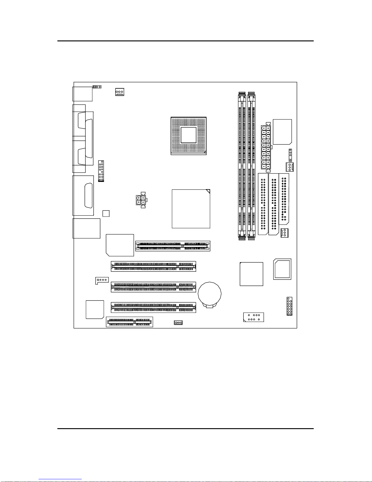
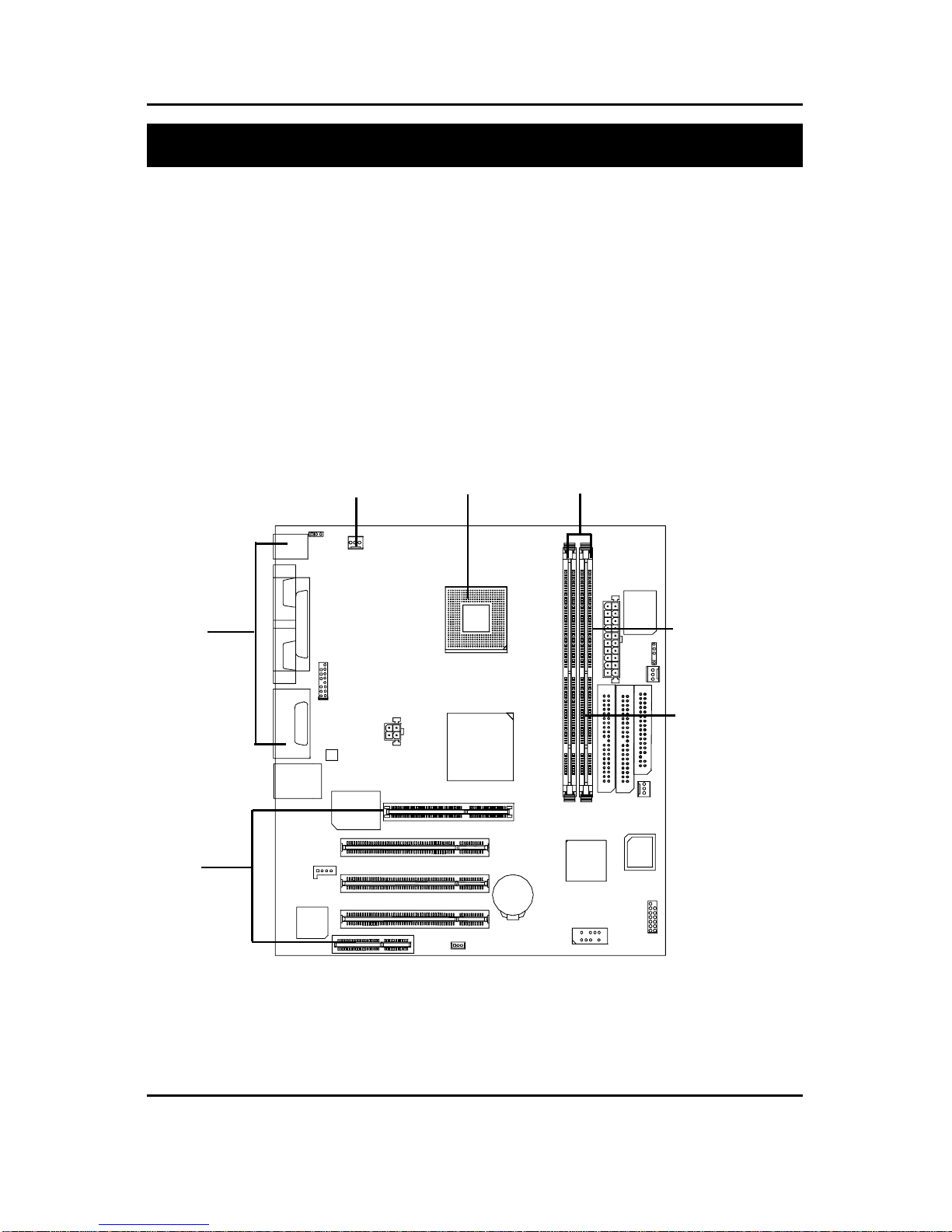
GA-8IDML Series Motherboard Layout......................................................8
Chapter 2 Hardware Installation Process................................................9
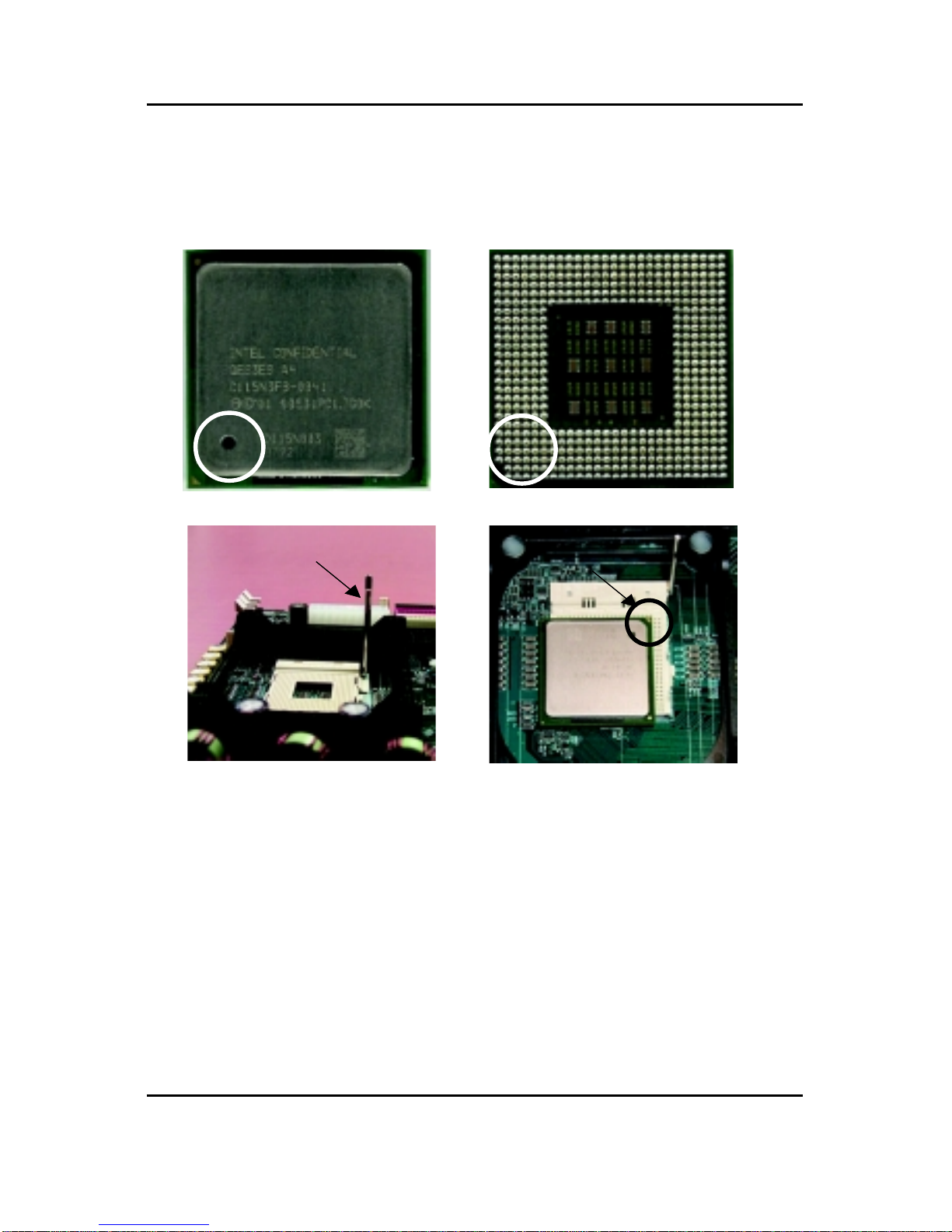
Step 1: Install the Central Processing Unit (CPU).....................................10
CPU Installation ............................................................................................................... 10
CPU Heat Sink Installation...............................................................................................11
Step 2: Install memory modules................................................................12
Step 3: Install expension cards .................................................................13
Step 4: Connect ribbon cables, cabinet wires, and power supply ...........14
I/O Back Panel Introduction ............................................................................................ 14
Connectors Introduction .................................................................................................. 16
Chapter 3 BIOS Setup ..........................................................................20
The Main Menu (For example: BIOS Ver. :F1).........................................21
Standard CMOS Features.........................................................................23
Advanced BIOS Features ..........................................................................27
Advanced Chipset Features ......................................................................29
Integrated Peripherals ..............................................................................32
Power Management Setup .......................................................................39

3
Table of Content
PnP/PCI Configurations.............................................................................43
PC Health Status........................................................................................45
Frequency/Voltage Control........................................................................47
Load Fail-Safe Defaults.............................................................................48
Load Optimized Defaults...........................................................................49
Set Supervisor/User Password..................................................................50
Save & Exit Setup.......................................................................................51
Exit Without Saving ...................................................................................52
Chapter 4 Technical Reference ............................................................53
Performance List .......................................................................................53
Block Diagram...........................................................................................54
Four Speaker & SPDIF Introduction..........................................................55
@ BIOS Introduction..................................................................................59
Easy TuneIIITM Introduction .......................................................................60
Chapter 5 Appendix..............................................................................61

4
GA-8IDML Series Motherboard
Revision RevisionNote Date
2.0 InitialreleaseoftheGA-8IDMLSeriesmotherboarduser'smanual. Jul.2001
The author assumes no responsibility for any errors or omissions that may appear in this
documentnordoestheauthormakeacommitmenttoupdatetheinformationcontainedherein.Third-party
brandsandnamesarethepropertyoftheirrespectiveowners.
TheGA-8IDMLSeriesmotherboard
IDE cable x 1/ Floppy cable x 1
CDformotherboarddriver & utility (IUCD)
GA-8IDMLSeriesuser’smanual
I/O Back Panel
Revision History
Item Checklist

5
WARNING!
Computermotherboards and expansioncards contain verydelicate Integrated Circuit(IC) chips.To
protectthemagainstdamagefromstaticelectricity,youshouldfollowsomeprecautionswheneveryou
workonyour computer.
1. Unplugyourcomputerwhenworkingontheinside.
2. Useagroundedwriststrapbeforehandlingcomputercomponents.Ifyoudonothave
one,touchbothofyourhandstoasafelygroundedobjectortoametalobject,suchas
thepower supply case.
3. HoldcomponentsbytheedgesandtrynottouchtheICchips,leadsorconnectors,or
othercomponents.
4. Placecomponentsonagroundedantistaticpadoronthebagthatcamewiththe
componentswheneverthecomponentsareseparatedfromthesystem.
5. EnsurethattheATXpowersupplyisswitchedoffbeforeyoupluginorremovetheATX
powerconnectoronthemotherboard.
Ifthemotherboardhasmountingholes,buttheydon’tlineupwiththeholesonthebaseandthereare
noslotstoattachthespacers,donotbecomealarmedyoucanstillattachthespacerstothemounting
holes.Justcutthebottomportionofthespacers(thespacermaybealittlehardtocutoff,sobecareful
ofyourhands).Inthiswayyoucanstillattachthemotherboardtothebasewithoutworryingaboutshort
circuits.Sometimesyoumayneedtousetheplasticspringstoisolatethescrewfromthemotherboard
PCBsurface,becausethecircuitwiremaybenearbythehole.Becareful,don’tletthescrewcontact
anyprintedcircuitwriteorpartsonthePCBthatarenearthefixinghole,otherwiseitmaydamagethe
boardorcauseboardmalfunctioning.
Installing the motherboard to the chassis…
WARNING!

6
GA-8IDML Series Motherboard
FormFactor 24.4cm x 22.4cm MicroATX size form factor, 4 layers PCB.
Motherboard GA-8IDMLSeriesMotherboard:
GA-8IDML and GA-8IDML-C
CPU Socket478 forIntel®MicroFC-PGA2Pentium®4processor
Intel Pentium®4 400MHzFSB
2ndcachedependonCPU
Chipset Chipset82845HOST/AGP/Controller
82801BA(ICH2) I/O Controller Hub
Memory 2168-pinDIMMsockets
SupportsPC-100/PC-133 SDRAM (Auto)
Supports only 3.3V SDRAM DIMM
NoRegisiteredDIMMsupport
I/OControl Winbond83627HF
Slots 1CNR(CommunicationandNetworkingRiser)Slot
1AGPslot4X(1.5V)device support
3 PCI slot supports 33MHz & PCI 2.2 compliant
On-BoardIDE AnIDEcontrolleron the Intel82801BAPCIchipset
provides IDE HDD/CD-ROM with PIO, Bus Master (Ultra
DMA33/ATA66/ATA100)operationmodes.
Canconnectupto fourIDEdevices
On-BoardPeripherals 1 Floppy portsupports2FDD with 360K, 720K,1.2M,1.44M
and 2.88Mbytes.
1ParallelportsupportsNormal/EPP/ECPmode
2 Serial ports (COMA&COMB)
4 USB ports (Rear USB x 2, Front USB x 2)
1IrDAconnectorforIR
HardwareMonitor CPU/Power/System Fan Revolution detect
CPU Fan Control
CPUOverheat Warning
Summary of Features
Chapter 1 Introduction
tobecontinued......

7
Introduction
"*" Only for GA-8IDML.
On-Board LAN BuildinRTL8100(B)LChipset*
On-Board Sound CreativeCT5880SoundChipset*
LineIn/Line Out/Mic In/CD In/Game Port
PS/2Connector PS/2KeyboardinterfaceandPS/2Mouseinterace
BIOS Licensed AWARD BIOS, 2M bit FWH
AdditionalFeatures PS/2 Keyboard power on by password
PS/2 Mouse power on
STR(Suspend-To-RAM)
Wakeon LAN
AC Recovery
USB KB/Mouse wake up from S3
Supports@BIOS
SupportsEasyTuneIII
SpecialFeatures Over Clock (CPU/PCI/AGP)
Pleasesetthe CPUhostfrequencyinaccordancewithyourprocessor’s specifications.
Wedon’trecommendyoutosetthesystembusfrequencyovertheCPU’sspecification
becausethesespecificbusfrequenciesarenotthestandardspecificationsforCPU,
chipsetandmostoftheperipherals.Whetheryoursystemcanrununder thesespecific
busfrequenciesproperlywilldepend onyourhardwareconfigurations,includingCPU,
Chipsets,SDRAM,Cards….etc.

8
GA-8IDML Series Motherboard
GA-8IDML Series Motherboard Layout
"*" Only for GA-8IDML.
GA-8IDML(-C)
KB_MS USB_VS
COMA
COMB LPT1
GAME
LINE_IN
LINE_OUT
MIC_IN
USB
LAN*
AUX_12V
CD_IN
F_AUDIO
RTL8100*
CT5880*
WOL
W83627HF
F_PANEL
BATTERY
FWH
SYS
FAN
ICH2
Brookdale
SOCKET478
CPU_FAN
ATX
PWR_FAN
FLOPPY
IDE2
AGP
PCI1
PCI2
PCI3
DIMM2
DIMM1
CNR
IR
FRONT USB
AC97
IDE1

9
Hardware Installation Processor
Tosetupyourcomputer,youmustcompletethefollowingsetups:
Step1-InstalltheCentralProcessingUnit(CPU)
Step2-Installmemorymodules
Step3-Installexpansioncards
Step4- Connectribboncables,cabinetwires, andpowersupply
Step5-SetupBIOSsoftware
Step6-Installsupportingsoftwaretools
Chapter 2 Hardware Installation Process
Step3
Step 4
Step 4
Step 4
Step 2Step1Step1

10
GA-8IDML Series Motherboard
Step 1: Install the Central Processing Unit (CPU)
CPU Installation
Please make sure the CPU type is supported by the motherboard.
Pin1 indicator Pin1indicator
CPU Top View CPU Bottom View
Socket Actuation Lever
1. Pull up the CPU socket level
andupto90-degreeangle.
Pin1 indicator
2. LocatePin1inthesocketandlook
fora(golden)cutedgeontheCPU
uppercorner.TheninserttheCPU
intothesocket.

11
Hardware Installation Processor
CPU Heat Sink Installation
1. Hookoneendofthecooler
brackettotheCPUsocketfirst. 2. Hooktheotherendofthe
coolerbrackettotheCPU
socket.
Please use Intel approved cooling fan.
Make sure the CPU fan power cable is plugged in to the CPU fan connector,
this completes the installation.
Please refer to CPU heat sink user’s manual for more detail installation
procedure.

12
GA-8IDML Series Motherboard
Step 2: Install memory modules
Themotherboardhas2 dual in-linememorymodule(DIMM)socketssupport4banks. TheBIOSwill
automaticallydetectsmemorytypeandsize.Toinstallthememorymodule,justpushitverticallyintothe
DIMMSlot.TheDIMMmodulecanonlyfitinonedirectionduetothetwonotch.Memorysizecanvary
betweensockets.
1. TheDIMM slot has two notch, so the
DIMMmemory module can only fitin
onedirection.
2. Insertthe DIMM memory module
verticallyintotheDIMMslot.Then
pushitdown.
3. Closethe plasticclipatbothedgesoftheDIMMslotsto lock theDIMMmodule.
Reversetheinstallationsteps when youwishtoremovetheDIMMmodule.
SDRAM
When STR/DIMM LED is ON, do not install/remove SDRAM from socket.

13
Hardware Installation Processor
Step 3: Install expension cards
1. Readtherelatedexpansioncard’sinstructiondocumentbeforeinstalltheexpansioncardinto
thecomputer.
2. Removeyourcomputer’schassiscover, necessaryscrewsandslotbracketfromthecomputer.
3. Presstheexpansioncardfirmlyintoexpansionslotinmotherboard.
4. Besurethemetalcontactsonthecardareindeedseatedintheslot.
5. Replacethescrewtosecuretheslotbracketoftheexpansioncard.
6. Replaceyourcomputer’schassiscover.
7. Poweronthecomputer,ifnecessary,setupBIOSutilityof expansion card from BIOS.
8. Installrelateddriverfromtheoperatingsystem.

14
GA-8IDML Series Motherboard
Step 4: Connect ribbon cables, cabinet wires, and power
supply
I/O Back Panel Introduction
PS/2 Keyboard and PS/2 Mouse Connector
Parallel Port and Serial Ports (COM1/COM2)
PS/2MouseConnector
(6pinFemale)
PS/2KeyboardConnector
(6pinFemale)
ParallelPort
(25pinFemale)
COMA COMB
SerialPorts(9 pinMale)
ThisconnectorsupportsstandardPS/2
keyboardandPS/2mouse.
Thisconnectorsupports2standardCOM ports
and1Parallelport.Devicelike printercanbe
connectedtoParallelport;mouseandmodem
etccanbeconnectedtoSerialports.

15
Hardware Installation Processor
Game /MIDI Ports
Joystick/MIDI (15pin Female)
USB/LAN Connector
Audio Connectors
Thisconnectorsupportsjoystick,MIDIkeyboardandother
relateaudiodevices.
Afterinstallonboardaudiodriver, youmayconnect
speakertoLineOutjack, micro phone to MIC Injack.
Devicelike CD-ROM, walkman etc can be connected
toLine-Injack.
Before you connect your device(s) into USBconnector(s),
pleasemake sureyour device(s) such as USB keyboard,
mouse,scanner,zip,speaker..etc.Haveastandard USB
interface.Also makesure yourOS (Win95 withUSB
supplement,Win98,Windows2000,WindowsME,Win
NTwithSP6)supportsUSBcontroller. If your OS does not
supportUSBcontroller,pleasecontactOSvendorforpos-
siblepatchordriverupgrade.Formoreinformationplease
contactyour OS or device(s)vendors.
LineIn
MIC In
LineOut
USB 0
USB 1
LAN*
Connector
"*" Only for GA-8IDML.

16
GA-8IDML Series Motherboard
ConnectorsIntroduction
A CPU_FAN I FRONT_USB
B ATX J BATTERY
C IR K WOL
D PWR_FAN L CD_IN
E FLOPPY M AUX_12V
F IDE1/IDE2 N F_AUDIO
G SYS_FAN O USB_VS
H F_PANEL
A
B
C
D
E
F
H
I
J
K
L
O
N
M
G

17
Hardware Installation Processor
A/ D / G : CPU_FAN / PWR_FAN / SYS FAN Connector
B :ATX Power
1
2
3
4
+12V
GND +12V
GND
+12V Power
Thisconnector(ATX+12V)isused
only for CPU Core Voltage.
M : +12V Power Connector
+12V/Control
GND
Sense
1
SYS_FAN
+12V/Control
GND
Sense 1
PWR_FAN
1
CPU_FAN
+12V/Control
Sense
GND
PS-ON(SoftOn/Off)
3.3V
3.3V
GND
GND
GND
VCC
VCC
+12V
5V SB (Stand by +5V)
PowerGood
3.3V
GND
GND
GND
GND
VCC
VCC
-12V
ATXPower
1
20
-5V

18
GA-8IDML Series Motherboard
L : CD_IN
CD_IN
1CD-L
CD-R
GND
N: F_AUDIO Connector
K :WOL
1
+5V SB
GND
Signal
E / F : Floppy / IDE1 / IDE2 Connector
IDE2
1
IDE1
1
Floppy
1
IncaseSpeaker(R)
GND IncaseSpeaker(L)
+12V
MIC
GND GND
GND
GND
GND
FrontAudio(R)
FrontAudio(L) RearAudio(R)
RearAudio(L)

19
Hardware Installation Processor
J:Battery
Dangerofexplosionifbatteryisincorrectly
replaced.
Replaceonlywiththesameorequivalent
typerecommendedbythemanufacturer.
Disposeofusedbatteriesaccordingtothe
manufacturer’sinstructions.
+
O: USB_VS : PS/2 USB Wake Up
selection
1-2close:Enable
2-3close:Disable(Default)
1
1
C:IR I :Front USB
H :F_PANEL
PW-
NC
IRTX
IRRX
GND
VCC
SPK+
SPK- PD_G
PD_G
HD- HD+
PW+
RST+
RST-
PD+
GND
NC
USB D3+
USB D3-
Power
Power
USB D2-
USB D2+
NC
GND

8IDML Series Motherboard
20
<> Movetopreviousitem
<> Movetonext item
<> Movetotheiteminthelefthand
<> Movetotheitemintherighthand
<Esc> MainMenu-QuitandnotsavechangesintoCMOSStatus Page Setup Menu and
OptionPageSetupMenu-ExitcurrentpageandreturntoMainMenu
<+/PgUp> Increasethenumericvalueormakechanges
<-/PgDn> Decreasethenumericvalueormakechanges
<F1> Generalhelp,onlyforStatusPageSetupMenuandOptionPageSetupMenu
<F2> Reserved
<F3> Reserved
<F4> Reserved
<F5> Restorethe previous CMOS value fromCMOS, only for Option PageSetup Menu
<F6> LoadthedefaultCMOSvaluefromBIOSdefaulttable,onlyforOptionPageSetup
Menu
<F7> LoadtheSetupDefaults
<F8> Reserved
<F9> Reserved
<F10> Save all the CMOS changes, only for Main Menu
BIOSSetupisanoverviewoftheBIOSSetupProgram.The program that allows users to modify the
basicsystemconfiguration.Thistypeofinformationisstoredinbattery-backedCMOSRAMso thatit
retainstheSetupinformationwhenthepoweristurnedoff.
ENTERINGSETUP
PowerON thecomputer andpress <Del> immediately will allow you to enter Setup. If themessage
disappearsbeforeyourespondandyoustillwishtoenterSetup,restartthesystemtotryagainbyturning
it OFF then ON or pressing the “RESET” bottom on the system case. You may also restart by
simultaneously press <Ctrl> - <Alt>- <Del> keys.
CONTROLKEYS
Chapter 3 BIOS Setup
Table of contents
Other Pentium Motherboard manuals

Pentium
Pentium GA - 586IP User manual

Pentium
Pentium P55-IT User manual

Pentium
Pentium 5VD2 Use and care manual

Pentium
Pentium 5VC2 Use and care manual

Pentium
Pentium P5V580 VP3 Advance II User manual

Pentium
Pentium P51437P4/FMB User manual

Pentium
Pentium P51430VX-280DM Explorer III User manual

Pentium
Pentium GA - 586ATV User manual

Pentium
Pentium GA - 586AL User manual

Pentium
Pentium Explorer IV User manual