INTRODUCTION
MB740 User’s Manual 3
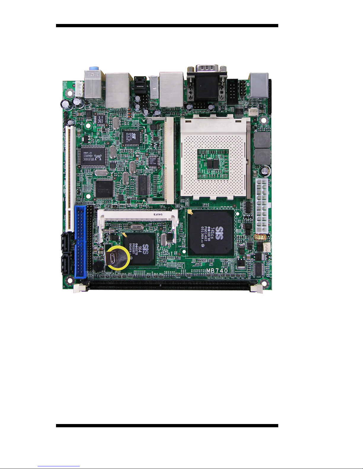
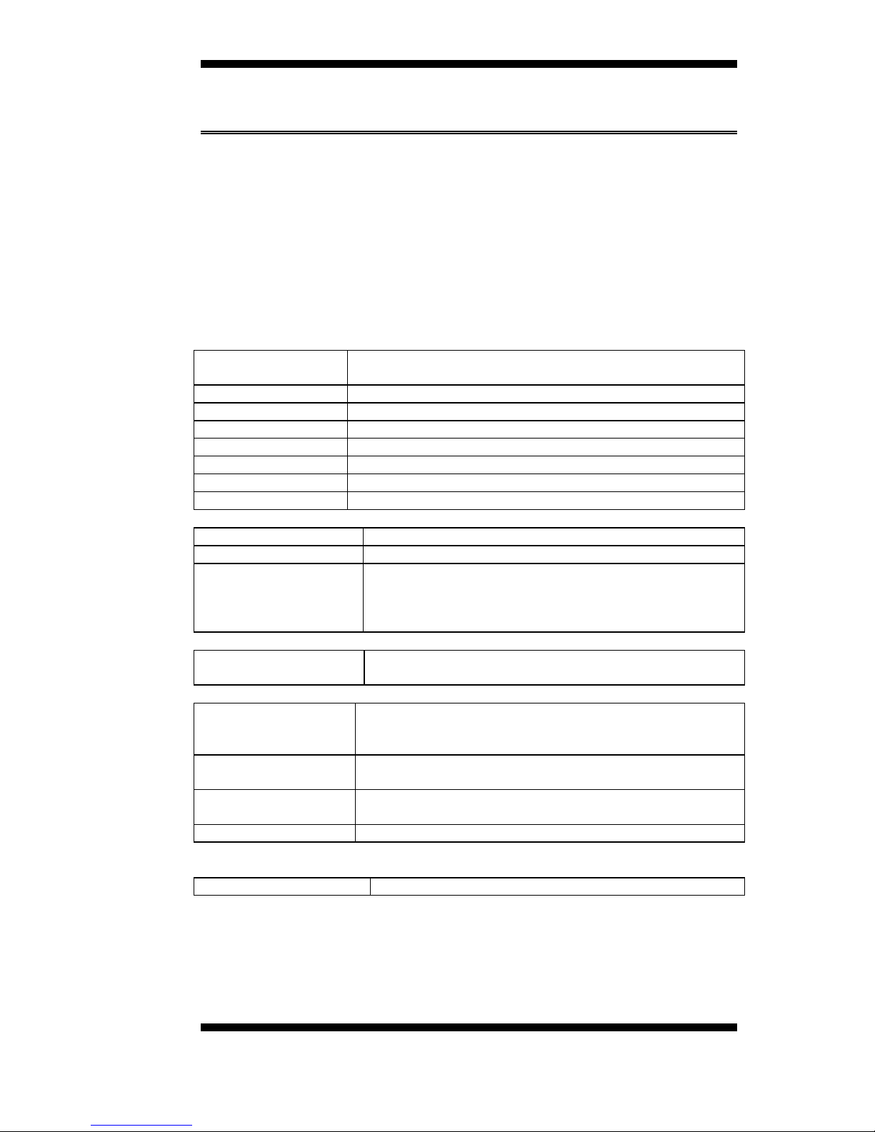
MB740 Specifications
[
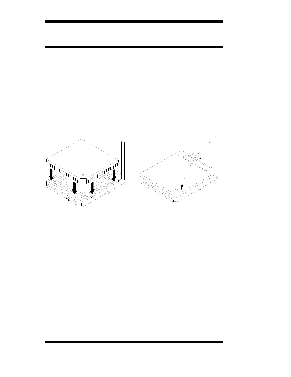
Features Socket A for AMD Geode NX processor
Up to 1.4GHz speed, 133MHz FSB
DDR DIMM x 1, max. 1GB, DDR266/333
Onboard 10/100 and Optional Realtek 8110S Gigabit LAN
Integrated SiS 741CX CRT VGA
Optional CRT2/DVI, optional LVDS/TV out
2 x SATA, 6 x USB 2.0, 2 x COM, watchdog timer
Digital I/O, optional 1394, 1x PCI, 1x Mini PCI
System
CPU Socket A (462-pin) for AMD Geode, up to 1.4GHz
(NX1250 = 667MHz, NX1500 = 1GHz, NX1750 =1.4GHz)
System Memory DDR DIMM x 1, max. 1GB, DDR333
System Chipset SiS 741CX + SiS 964
BIOS Award 4Mbit
Watchdog Timer 256 levels
SSD Optional CF socket (on solder side via IDE2)
H/W Monitor Yes
Expansion Slot 1 PCI, 1 Mini PCI, 1 MicroAGP
Graphics
VGA Controller SiS 741CX integrated for CRT
VGA Memory Shared memory; Max. 64MB
LCD / TV-out / DVI /
CRT2 Optional SiS 302LV MicroAGP card (IBA140-302)
supports 18/24-bit dual channel LVDS and TV out;
Optional SiS 301 MicroAGP card (IBA140-301)
supports DVI/CRT2 interface
Ethernet
Controller SiS 964 built-in 10/100 and Optional Realtek
RTL8110S-32 Gigabit LAN
Multi I/O
Chipset SiS 964, ITE 8705
2x IDE (UDMA33/66/100), 1x FDD, 1x KB, 1x Mouse; 2x
RS-232, 2x SATA
USB 4 ports on board
Pin header for 2 additional ports (USB 2.0)
Audio SiS 964 built-in audio + AC97 codec, SPDIF support;
2W+2W volume amplifier
Others 1394, ATX power connector
Mechanical and Environmental
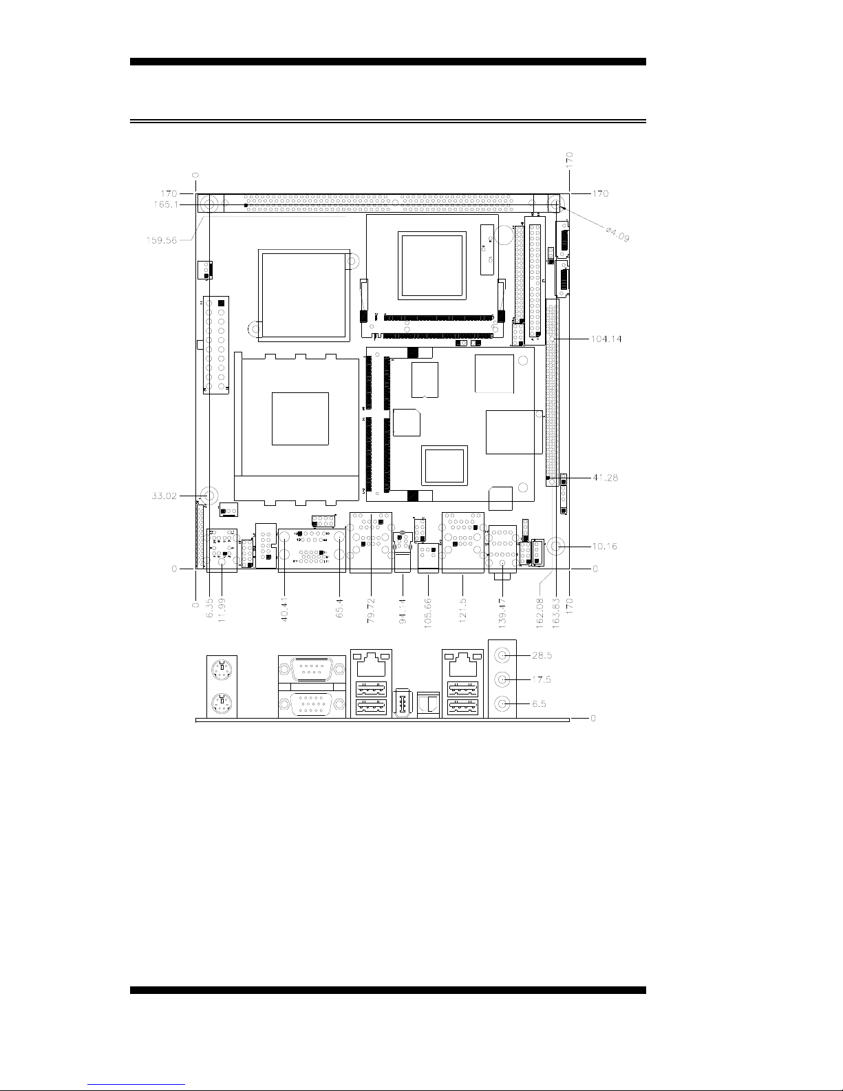
Dimensions 170mm x 170mm