Pepperl+Fuchs VisuNet GXP Series User manual

VisuNet GXP
RM-GXP1100-19S
RM-GXP1200-19S
PC-GXP1100-19S
PC-GXP1200-19S
Manual

With regard to the supply of products, the current issue of the following document is applicable: The
General Terms of Delivery for Products and Services of the Electrical ndustry, published by the Central
Association of the Electrical ndustry (Zentralverband Elektrotechnik und Elektroindustrie (ZVE ) e.V.)
in its most recent version as well as the supplementary clause: "Expanded reservation of proprietor-
ship"
Worldwide
Pepperl+Fuchs Group
Lilienthalstr. 200
68307 Mannheim
Germany
Phone: +49 621 776 - 0
E-mail: inf[email protected]hs.com
North Ameri an Headquarters
Pepperl+Fuchs nc.
1600 Enterprise Parkway
Twinsburg, Ohio 44087
USA
Phone: +1 330 425-3555
E-mail: [email protected]
Asia Headquarters
Pepperl+Fuchs Pte. Ltd.
P+F Building
18 Ayer Rajah Crescent
Singapore 139942
Phone: +65 6779-9091
E-mail: [email protected]-fuchs.com
https://www.pepperl-fuchs.com

3
VisuNet GXP
Contents
2020-04
1 Introdu tion................................................................................................................ 4
1.1 Content of this Do ument............................................................................. 4
1.2 Target Group, Personnel ............................................................................... 4
1.3 Symbols Used ................................................................................................ 5
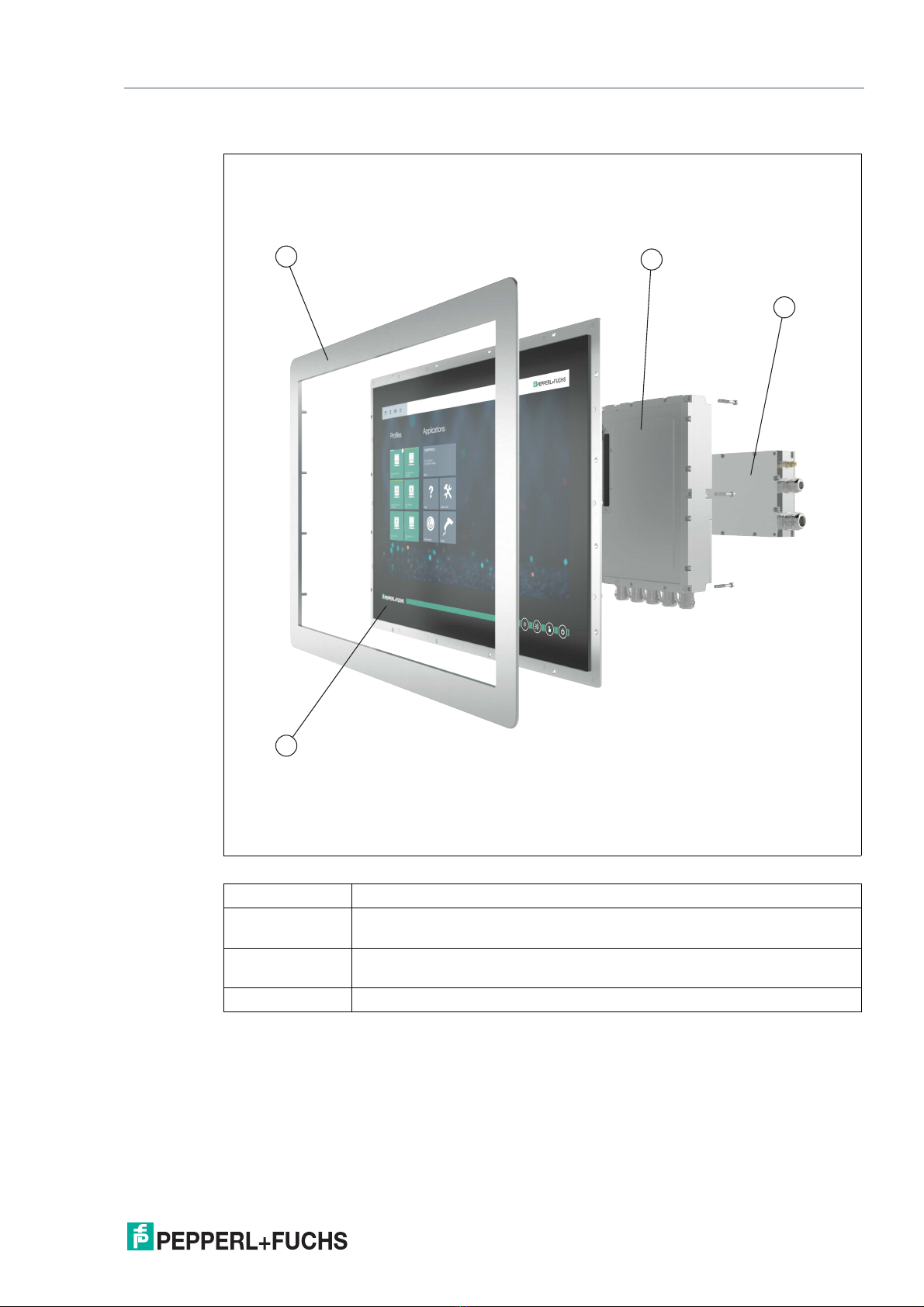
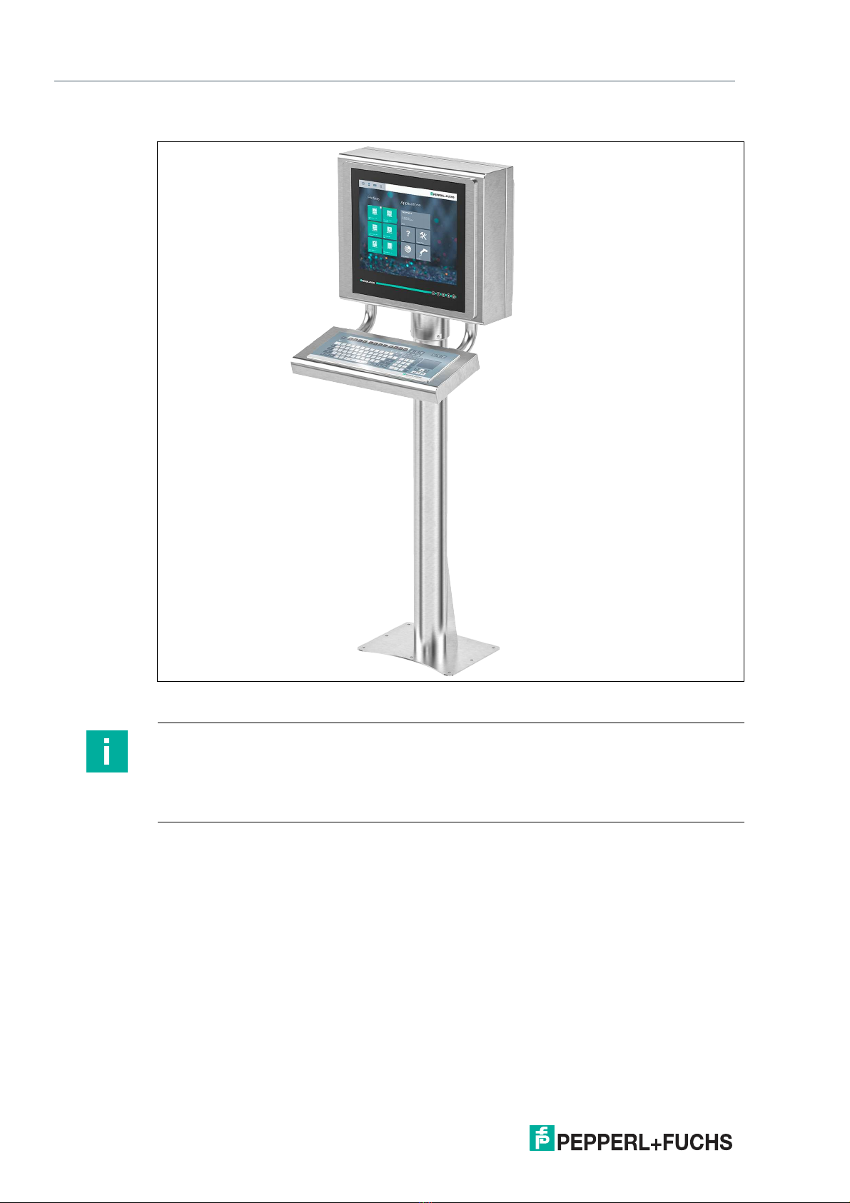
2 Produ t Des ription .................................................................................................. 6
2.1 Overview......................................................................................................... 6
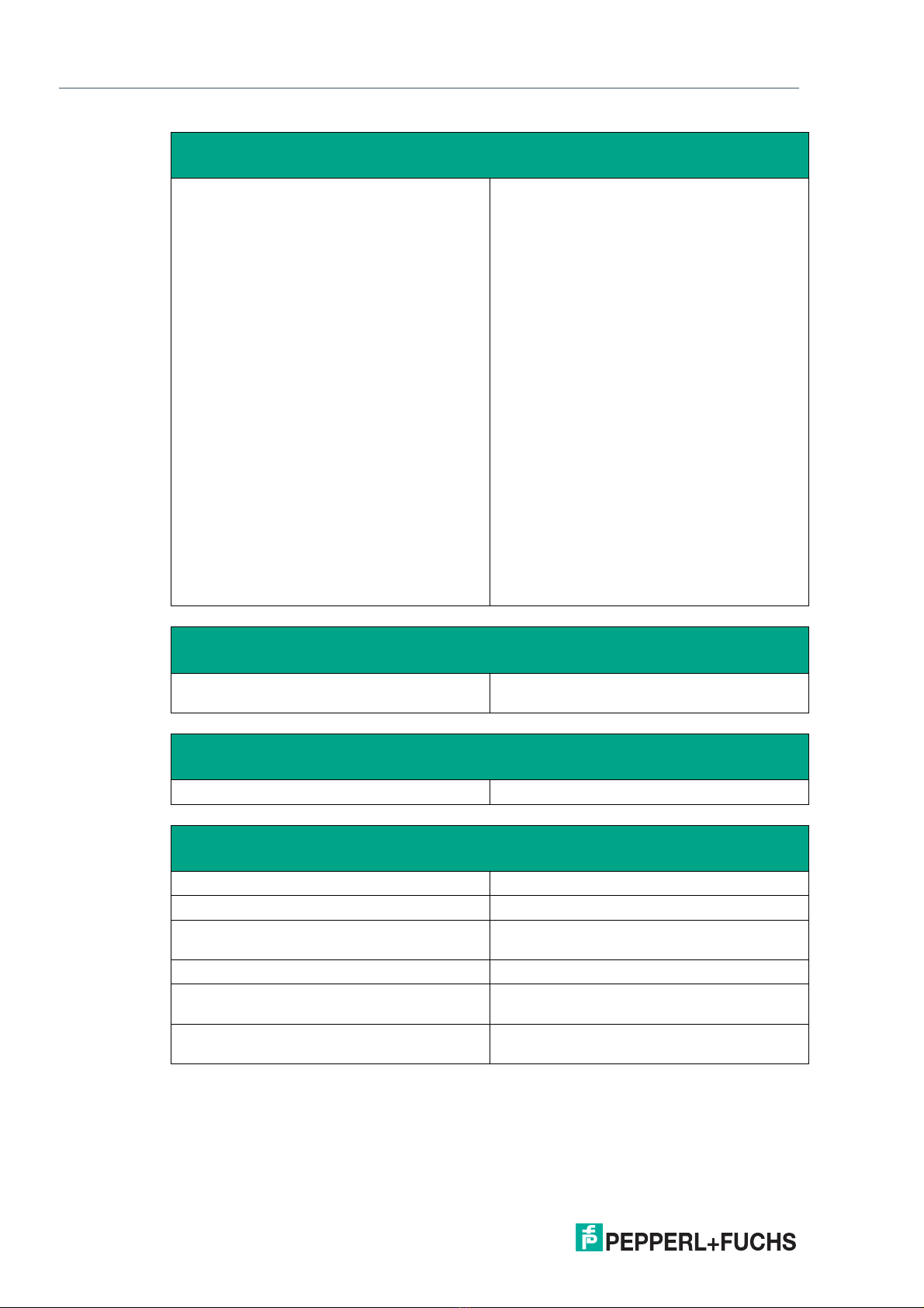
2.2 Te hni al Spe ifi ations ............................................................................... 9
2.3 Dimensions................................................................................................... 12
2.4 Disposal........................................................................................................ 14
3 Me hani al Installation ........................................................................................... 15
3.1 General Installation Requirements ............................................................ 15
3.2 Installation Tools.......................................................................................... 15
3.3 System Installation ...................................................................................... 16
3.3.1 Preparation for System nstallation................................................... 16
3.3.2 Preparing the GXP Panel/Housing ................................................... 17
3.3.3 Preparing the StandardLine Pedestal .............................................. 20
3.3.4 Attaching the Pedestal to the Housing ............................................. 24
3.3.5 Opening the Housing ....................................................................... 27
3.3.6 Grounding the Housing to the Pedestal ........................................... 29
3.3.7 Mounting the Keyboard.................................................................... 31
3.3.8 Mounting the Scanner Holder to the AG1 Housing .......................... 33
3.3.9 nstalling the Handheld 1-D/2-D Code Reader................................. 37
3.4 Repla ing a VisuNet EX1 with the 19-In h VisuNet GXP.......................... 43
3.4.1 Removing VisuNet EX1 from AG1 Housing...................................... 44
3.4.2 nstalling VisuNet GXP into AG1 Housing ........................................ 46
3.5 Panel Mount Installation ............................................................................. 49
3.6 Wall Mount Installation................................................................................ 52
4 Appendix .................................................................................................................. 54
4.1 A essories.................................................................................................. 54
4.2 UL Control Drawing ..................................................................................... 55

2020-04
4
VisuNet GXP
ntroduction
1 Introdu tion
1.1 Content of this Do ument
This document contains information that you need in order to use your product throughout the
applicable stages of the product life cycle. These can include the following:
•Product identification
•Delivery, transport, and storage
•Mounting and installation
•Commissioning and operation
•Maintenance and repair
•Troubleshooting
•Dismounting
•Disposal
The documentation consists of the following parts:
•Present document
•nstruction manual
•Datasheet
Additionally, the following parts may belong to the documentation, if applicable:
•EU-type examination certificate
•EU declaration of conformity
•Attestation of conformity
•Certificates
•Control drawings
•Additional documents
1.2 Target Group, Personnel
Responsibility for planning, assembly, commissioning, operation, maintenance, and dismount-
ing lies with the plant operator.
Only appropriately trained and qualified personnel may carry out mounting, installation, com-
missioning, operation, maintenance, and dismounting of the product. The personnel must have
read and understood the instruction manual and the further documentation.
Prior to using the product make yourself familiar with it. Read the document carefully.
Note
This document does not substitute the instruction manual.
Note
For full information on the product, refer to the instruction manual and further documentation on
the nternet at www.pepperl-fuchs.com.

VisuNet GXP
ntroduction
2020-04
5
1.3 Symbols Used
This document contains symbols for the identification of warning messages and of informative
messages.
Warning Messages
You will find warning messages, whenever dangers may arise from your actions. t is mandatory
that you observe these warning messages for your personal safety and in order to avoid prop-
erty damage.
Depending on the risk level, the warning messages are displayed in descending order as fol-
lows:
Informative Symbols
A tion
This symbol indicates a paragraph with instructions. You are prompted to perform an action or
a sequence of actions.
Danger!
This symbol indicates an imminent danger.
Non-observance will result in personal injury or death.
Warning!
This symbol indicates a possible fault or danger.
Non-observance may cause personal injury or serious property damage.
Caution!
This symbol indicates a possible fault.
Non-observance could interrupt the device and any connected systems and plants, or result in
their complete failure.
Note
This symbol brings important information to your attention.

2020-04
6
VisuNet GXP
Product Description
2 Produ t Des ription
2.1 Overview
The Pepperl+Fuchs VisuNet Remote Monitors GXP RM-GXP1100-19S*/RM-GXP1200-19S*
and PC-GXP-1100-19S*/PC-GXP-1200-19S* are ATEX/ ECEx certified, UL listed devices
intended for use in potentially explosive atmospheres, such as Zones 1/21, 2/22 and Class
Div. 2, Class Div. 2, and Class .
The VisuNet GXP serves as a thin client- or PC-based operator workstation that uses standard
Ethernet technology to transmit process information from a process control or manufacturing
execution system into hazardous areas.
The assembly consists of several core devices that can be exchanged by the customer:
•The display units DPU1100-* and DPU1200-* are display panels with optional 10-finger
multi-touch sensors. The displays and touch-sensors are optically bonded with the hard-
ened front glass.
•The thin client units TCU1100-* and TCU1200-* are computing units running the latest
Pepperl+Fuchs RM Shell 5.x or RM Shell 4.x firmware. They allow connectivity to various
host systems in the safe area using standard Ethernet technology. The computing units
PCU1100-* and PCU1200-* run an open Microsoft® Windows® operating system, allow-
ing installation of any software, such as SCADA packages.
•The power supply units PSU1100-* and PSU1200-* provide the above-listed devices with
24 V DC power. They are available as DC and AC versions.
As the standard mounting option, a bezel is available that allows the panel to be mounted into a
system housing or cabinet that needs to be ordered separately. The panel can also be flush-
mounted into a cabinet from behind.

VisuNet GXP
Product Description
2020-04
7
Figure 2.1 VisuNet GXP panel components
VisuNet GXP Panel Components
1Bezel for housing and panel mounting
2Computing unit (TCU or PCU): processor, SSD and memory, Ex circuits,
interface modules
3Power supply unit: DC or AC option, backpacked (panel-mount) or stand-
alone (in system enclosure)
4Display unit: display, touch screen, hardened front glass
12
3
4

2020-04
8
VisuNet GXP
Product Description
Figure 2.2 VisuNet GXP system mounted in AG1 Housing with Pedestal5 -1458-* and EXTA2
keyboard/mouse (ordered separately)
VisuNet GXP Pedestal Mounted with Keyboard/Mouse
Note
For a description of the product model nomenclature, see the VisuNet GXP PC or VisuNet GXP
RM product datasheets at www.pepperl-fuchs.com.
For more mounting options and information, see the datasheet "Mounting Options
'StandardLine' and 'BasicLine'".

VisuNet GXP
Product Description
2020-04
9
2.2 Te hni al Spe ifi ations
Te hni al Data RM-GXP*
Te hni al Data PC-GXP*
Te hni al Data RM-GXP* and PC-GXP*
Hardware
Processor ntel® Atom™ Bay Trail E3827 1.75 GHz
RAM 2048 MB DDR3L
Mass storage 32 GByte industrial grade MLC SSD
Software
Operating system VisuNet RM Shell 5.x (based on Microsoft®
Windows® 10 oT LTSB)
Hardware
Processor ntel® Atom™ Bay Trail E3845 1.91 GHz
RAM 4096 MB DDR3L
Mass storage 128 GByte industrial grade MLC SSD
Software
Operating system Microsoft® Windows® 10 oT Enterprise x64
Supply
Power consumption
AC 115/230 V AC, 0.4 ... 0.7 A, 50/60 Hz
DC 18 ... 36 V DC , 1.5 ... 3 A

2020-04
10
VisuNet GXP
Product Description
Interfa e
nterface type 1 x Ethernet 100/1000BASE-TX (Ex e) or
1 x fiber optic 1000BASE-SX (Multimode) or
1 x fiber optic 1000BASE-LX (Singlemode)
1 x USB 2.0 (Ex e)
2 x USB 1.1 (Ex i; intended for Pepperl+Fuchs
keyboard and mouse)
1 x DC or AC power in (via power supply unit)
Optional:
1 x barcode reader interface Pepperl+Fuchs
Pscan-D/B (Ex i)
"interface 3": 1 x barcode reader interface for
wired 1-D scanners DM-160-D*, DM-Z1-
160-D-* and base station DMx61-B-* and
DM-Z1-x61-B-*
"interface 4": 1 x barcode reader interface for
wired 2-D Scanner DM-Z1-260-D-* (Ex i)
"interface 5": 1 x RS-232 interface with Power
Supply for miscellaneous devices and periph-
erals (Ex i)
1 x RS-232 (Ex e)
1 x RS-485 (Ex e)
1 x Ethernet 100/1000Base-TX (Ex e)
Bluetooth v4.0, communication distance up to
30 m in open terrain, transmission power +8
dBm, transmission frequency 2.402 ... 2.48
GHz
Ele tromagneti ompatibility
Directive 2014/30/EU EN 61326-1:2013 (industrial locations)
non-Bluetooth products only
RoHS
Directive 2011/65/EU (RoHS) EN 50581:2012-09
Ambient onditions
Operating temperature -20 ... 50 °C (-4 ... 122 °F)
Storage temperature -20 ... 60 °C (-4 ... 140 °F)
Relative humidity 93% at 40°C, non-condensating, according to
EN60068-2-78
Altitude Operating altitude max. 2000 m
Shock resistance 18 shocks 15 g , 11 ms all axis, EC 60068-2-
27
Vibration resistance 10 ... 150 Hz, +/- 0.075 mm , 1g, 10 cycles per
axis according to EN60068-2-6

VisuNet GXP
Product Description
2020-04
11
Marking
UL Marking
Me hani al spe ifi ations
Degree of protection P66 (individual components and entire sys-
tem with housing)
Material nternal:
Panel: anodized aluminum (TCU, PSU), pow-
der coated aluminum (DPU)
External:
Bezel: stainless steel A S 304 (1.4301)
System housing: stainless steel A S 304
(1.4301), ground smooth, typical surface
roughness Ra = 0.8 µm
Mass panel with DC: 22 kg , panel with AC: 23 kg ,
system housing AG1: 19 kg
Dimensions panel with DC: 524 mm x 453 mm x 120 mm
panel with AC: 524 mm x 453 mm x 137 mm
panel with AG1 housing: 582 mm x 490 mm x
224 mm
Note
For more technical information, refer to the manuals and instruction manuals of the individual
components:
•Display Units DPU1100-J1* and DPU1200-J2*
•AC Power Supply Units PSU1100-J1-AC-N0 and PSU1200-J2-AC-N0
•DC Power Supply Units PSU1100-J1-DC-N0 and PSU1200-J2-DC-N0
•Thin Client Units TCU1100-J1-* and TCU1200-J2-*
•Computing Units PCU1100-J1-* and PCU1200-J2-*
ATEX
RM-GXP1100-J1-* 2G Ex eb q ib [ib] C T4 P66 Gb
2D Ex tb [ib] C T85°C P66 Db
RM-GXP1200-J2-* 3G Ex ec [ib] q C T4 P66 Gc
3D Ex tc [ib] C T85 °C P66 Dc
IECEx
RM-GXP1100-J1-* Ex eb q ib [ib] C T4 P66 Gb
Ex tb [ib] C T85°C P66 Db
RM-GXP1200-J2-* Ex ec [ib] q C T4 P66 Gc
Ex tc [ib] C T85 °C P66 Dc

2020-04
12
VisuNet GXP
Product Description
2.3 Dimensions
Dimensions with AG1 Housing and Pedestal
Figure 2.3 Dimensions with StandardLine Pedestal5-1458-Fix and EXTA2 keyboard/mouse—sample
configuration
582
490
1702
228
475
1100
Note
Keyboard/mouse and pedestal are ordered separately.

VisuNet GXP
Product Description
2020-04
13
Panel Dimensions with Bezel
Panel Cut-Out Dimensions
Cut-out dimensions: 480 x 400 mm. For more information, see chapter 3.5.
524 137
453
499
480
167
419
400
270
Ø 6.5 ± 0.5 (14 x)

2020-04
14
VisuNet GXP
Product Description
Wall Mount Dimensions
Figure 2.4 Wall mount dimensions with additional wall brackets (#198768)
2.4 Disposal
Follow all local and any other requirements for disposing of electronic equipment. When dis-
posing of any system component, mark VO D across all certification labels.
490
582
583
62
532
285
686
413

VisuNet GXP
Mechanical nstallation
2020-04
15
3 Me hani al Installation
3.1 General Installation Requirements
Observe the following requirements when installing the system components.
•The equipment must be installed by competent personnel in accordance with the instruc-
tions. National laws and regulations must be observed.
•The building installation must provide a 20 A overcurrent protection.
•The installer must make a readily accessible disconnect device available.
•The safety of any system incorporating the power supply unit is the responsibility of the
assembler of the system.
3.2 Installation Tools
•4-mm and 5-mm torque Allen keys
•Open-ended wrench for cable glands
•Screws for floor or wall mounting. Choose the appropriate screws based on the mounting
conditions.
•Small cable ties
•Side cutters
•Strong adhesive tape, such as duct tape or packing tape
•At least 1 piece of thin, 2.5-m-long wire for pulling cables through the pedestal
Warning!
Risk of injury
Lifting the device on your own may lead to injury.
Do not attempt to lift the device on your own. Use a crane or have another person help you.

2020-04
16
VisuNet GXP
Mechanical nstallation
3.3 System Installation
3.3.1 Preparation for System Installation
Figure 3.1 Distance required between housing/pedestal assembly and wall
Warning!
Proper installation on the floor
t is the installer's responsibility to select a suitable location with sufficient strength to hold the
equipment. t is the installer's responsibility to select the proper screws based on the installa-
tion conditions.
Warning!
Distance between housing and wall
Provide at least 350 mm of space between the housing/pedestal assembly and the left wall.
This is required in order to properly open the housing and connect the GXP components.

VisuNet GXP
Mechanical nstallation
2020-04
17
3.3.2 Preparing the GXP Panel/Housing
The VisuNet GXP comes pre-assembled and consists of the core components display unit,
power supply unit, and thin client unit / power supply unit. f the AG1 housing option is chosen,
the panel is pre-mounted in the housing.
Required Components
•1 x pre-assembled VisuNet RM-GXP or PC-GXP panel (option: panel-mounted into AG1
housing)
•2 x protective tubes
•Screws for housing
•EXTA2 keyboard and PEDESTAL5-xxxx-* (ordered separately)
StandardLine Pedestal Floor-Mount Hole Pattern
Basi Line Pedestal Floor-Mount Hole Pattern
400
180 180
300
250
140
130
130 20
40
Ø 100
Ø 10
071
031
130
170
90
45°
10
5° 5°
184
Warning!
Risk of injury
Handling the devices with bare hands may cut fingers, hands, or wrists.
Wear gloves at all times during the installation process.

2020-04
18
VisuNet GXP
Mechanical nstallation
Preparing the Housing
1.
Remove the box and leave the protective foam blocks on the housing. Save the uncollapsed
box for further mounting steps.
2.
Wrap strong adhesive tape around the foam blocks to hold them onto the housing and protect
the components during mounting.
3.
Place the housing face down on a flat surface.
Warning!
Risk of injury
Lifting the GXP housing on your own may cause injury.
Do not attempt to lift the device on your own. Use a crane or have another person help you.
Warning!
Danger resulting from scratched display unit screen
Scratches on a display unit front screen weaken the glass structure and may result in broken
glass. Explosion protection is no longer ensured if a display unit with a scratched screen is
used.
NEVER use a display unit with a scratched front screen in a hazardous area. f the surface is
damaged in any way, return the display unit to Pepperl+Fuchs at once and replace it with a new
one.

VisuNet GXP
Mechanical nstallation
2020-04
19
4.
Remove and discard the screws from the bottom of the housing.

2020-04
20
VisuNet GXP
Mechanical nstallation
3.3.3 Preparing the StandardLine Pedestal
A variety of pedestals are available for floor mounting. For a complete list of available mounting
options, see the mounting options datasheet. Pedestals are shipped with an attached protec-
tive earth (PE) wire and screws for mounting the VisuNet GXP AG1 housing to the pedestal: 6 x
M8 countersunk screws and 2 x M6 countersunk screws.
StandardLine Pedestal
1Pre-installed PE wire
2Top cable opening
3Cable glands
1
2
3
Other manuals for VisuNet GXP Series
1
This manual suits for next models
4
Table of contents
Other Pepperl+Fuchs Monitor manuals

Pepperl+Fuchs
Pepperl+Fuchs VisuNet DPU2100 Series User manual

Pepperl+Fuchs
Pepperl+Fuchs VisuNet IND DM5 Series User manual

Pepperl+Fuchs
Pepperl+Fuchs DA6-SSI/A-U User manual

Pepperl+Fuchs
Pepperl+Fuchs KFD2-SR2-Ex2.W.SM User manual

Pepperl+Fuchs
Pepperl+Fuchs VBA-2E2A-KE4-ENC/SSI-S User manual

Pepperl+Fuchs
Pepperl+Fuchs VISUNET GMP DM User manual

Pepperl+Fuchs
Pepperl+Fuchs VisuNet GXP RM-GXP1100-22F User manual

Pepperl+Fuchs
Pepperl+Fuchs VisuNet GXP Series User guide

Pepperl+Fuchs
Pepperl+Fuchs VisuNet GMP DM200 Series User manual

Pepperl+Fuchs
Pepperl+Fuchs DPU1100-J1 Series User manual