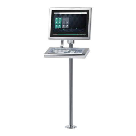
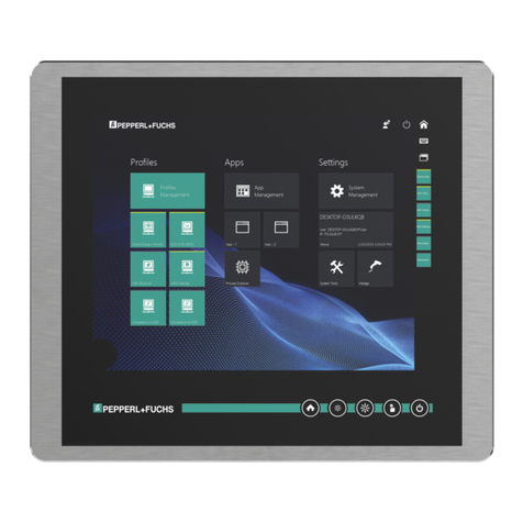
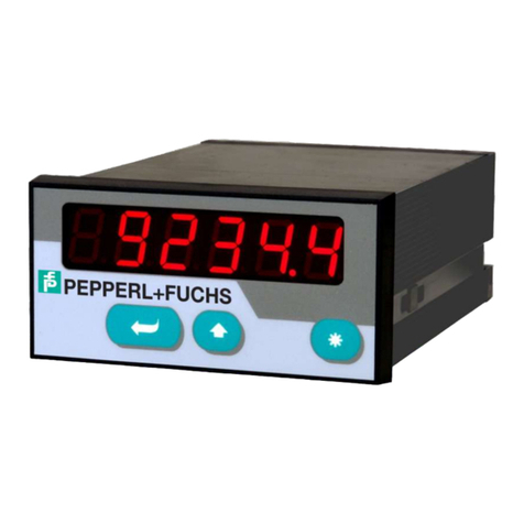
Pepperl+Fuchs VisuNet IND DM5 Series User manual

Industrial Flat Panel
Monitors
VisuNet IND DM5xx Series
Manual

With regard to the supply of products, the current issue of the following document is applicable:
The General Terms of Delivery for Products and Services of the Electrical Industry, published
by the Central Association of the Electrical Industry (Zentralverband Elektrotechnik und Elek-
troindustrie (ZVEI) e.V.) in its most recent version as well as the supplementary clause:
"Expanded reservation of proprietorship"
Worldwide
Pepperl+Fuchs Group
Lilienthalstr. 200
68307 Mannheim
Germany
Phone: +49 621 776 - 0
E-mail: info@de.pepperl-fuchs.com
North American Headquarters
Pepperl+Fuchs Inc.
1600 Enterprise Parkway
Twinsburg, Ohio 44087
USA
Phone: +1 330 425-3555
E-mail: sales@us.pepperl-fuchs.com
Asia Headquarters
Pepperl+Fuchs Pte. Ltd.
P+F Building
18 Ayer Rajah Crescent
Singapore 139942
Phone: +65 6779-9091
E-mail: sales@sg.pepperl-fuchs.com
https://www.pepperl-fuchs.com

Industrial Flat Panel Monitors
Contents
2023-07
3
1 System Operator and Personnel .............................................................................. 4
2 Introduction................................................................................................................ 5
3 Warnings and Cautions............................................................................................. 6
4 Certification Markings............................................................................................... 7
5 Conditions of Safe Use ........................................................................................... 10
6 Technical Specification ........................................................................................... 11
7 Power Supply ........................................................................................................... 12
8 Sunlight Readable Display...................................................................................... 13
9 Cabinet or Panel Mounting ..................................................................................... 14
10 Wiring the Monitor ................................................................................................... 17
11 Touch screen Interface............................................................................................ 21
12 Configuring the Video Software Drivers................................................................ 22
13 Adjusting Video Image 10'', 12'', 15'', & 19'' ..........................................................23
14 Adjusting the Video Image 21.5" & 22'' .................................................................26
15 Load Touch Screen Software (touch versions only) ............................................30
16 Maintenance............................................................................................................. 31
17 Other Information .................................................................................................... 32
18 Troubleshooting....................................................................................................... 33
19 Contact Us ................................................................................................................ 34

2023-07
4
Industrial Flat Panel Monitors
System Operator and Personnel
1 System Operator and Personnel
The operator of the system is responsible in terms of planning, mounting, commissioning,
operating, and maintenance.
Assembly, commissioning, operation, and dismounting of any devices may only be carried out
by trained, qualified personnel who have read and understood the instruction manual. No inter-
nal components are field replaceable. Any internal fuses or batteries must be replaced at the
factory.

Industrial Flat Panel Monitors
Introduction
2023-07
5
2 Introduction
Thank you for choosing a Pepperl+Fuchs VisuNet monitor. We have designed our products for
easy installation, configuration, and use. While there is nothing difficult or tricky about installing
this monitor, you should read this entire manual prior to installation. It is not long and may save
you some time in the end. If, after reading this manual and visually inspecting the monitor, you
are still unsure of how to properly install and operate, please ask for assistance.
This monitor can be used as either a digital or an analog monitor. This means it is designed to
automatically work with any standard DVI or VGA connection from a computer. There are no
special hardware modules, PROMS, cables, or custom software drivers required.

2023-07
6
Industrial Flat Panel Monitors
Warnings and Cautions
3 Warnings and Cautions
When so labeled, this equipment is suitable for use in Class I, Division 2, Groups A, B, C, and
D; Class II, Division 2, Groups F, G; ATEX \ IECEx Zone 2; or non-hazardous locations only.
When so labeled and installed in an enclosure that reduces environment to a Division 2/Zone
2/Zone 22 or non-hazardous location, this equipment is suitable for use in Class I, Division 1
Groups A, B, C, and D, and Class II Division 1 Groups F and G, as well as ATEX/IECEx Zone 1.
When powered, internal voltages present can be lethal. There are no user serviceable parts
inside. Direct all service work to the manufacturer or an authorized repair facility. This product
contains sensitive electronic components and glass. Dropping or extreme shocks may damage
or break the glass. Such abuse is not covered under warranty. This product is intended to be
mounted in a suitable cabinet or other enclosure. The NEMA 12, 13, 4 ratings are applicable
only when properly installed in a like rated enclosure. All peripheral equipment must also be
suitable for the location it is used in.
Power, input, and output (I/O) wiring must be in accordance with Class I, Class II/Div. 2 wiring
methods [Article 501.4(B) of the National Electrical Code, [NFPA 70] and in accordance with
the authority having jurisdiction. The cabinet for installations in Division 2 must be suitable for
Div. 2 wiring.
This product contains a high-voltage inverter circuit. When powered, internal voltages present
can be lethal.There are no user serviceable parts inside. Please direct all service work to the
manufacturer or an authorized repair facility.
This product contains sensitive electronic components and glass. Dropping or extreme shocks
may damage or break the glass. Such abuse is not covered under warranty.
This product is intended to be mounted in a suitable cabinet or other enclosure. The NEMA 12,
13, 4 ratings are applicable only when properly installed in a like rated enclosure. All peripheral
equipment must also be suitable for the location it is used in.
Where “ATEX \ IECEx”appears throughout this document, it shall be understood that ‘ATE X”
applies to ATEX installation applications only, and “IECEx”applies to IECEx installation applica-
tions only.
Warning!
EXPLOSION HAZARD. DO NOT DISCONNECT WHILE THE CIRCUIT IS LIVE OR UNLESS
THE AREA IS KNOWN TO BE FREE OF IGNITIBLE CONCENTRATIONS.
AVERTISSEMENT - RISQUE D'EXPLOSION - AVANT DE DECONNECTER L'EQUIPEMENT,
COUPER LE COURANT OU S'ASSURER QUE L'EMPLACEMENT EST DESIGNE NON DAN-
GEREUX.
Warning!
EXPLOSION HAZARD-SUBSTITUTION OF COMPONENTS MAY IMPAIR SUITABILITY FOR
USE IN DIVISION 2.
AVERTISSEMENT - RISQUE D'EXPLOSION - LA SUBSTITUTION DE COMPOSANTS PEUT
RENDRE CE MATERIEL INACCEPTABLE POUR LES EMPLACEMENTS DE DIVISION 2.
Industrial Flat Panel Monitors
Certification Markings
2023-07
7
4 Certification Markings
Labels for V3 Option
Figure 4.1
Figure 4.2

2023-07
8
Industrial Flat Panel Monitors
Certification Markings
Label for D1 Option
Figure 4.3
Certification for V3 Option
ATEX Certificate:
DEMKO 14 ATEX 1379X
IECEx Certificate:
IECEx UL 14.0090X
ATEX Marking:
II 3G
Marking with touch screen:
Ex nA nC IIC T4 Gc
Marking without touch screen:
Ex nA IIC T4 Gc
Standards:
IEC EN 60079-0:2012/A11:2013
IEC EN 60079-15:2010
UL File E190294
Model Current Rating
DM512 1.2 A max.
DM515 2.5 A max.
DM519 3.8 A max.
DM521 4.1 A max.
DM522 4.4 A max.

Industrial Flat Panel Monitors
Certification Markings
2023-07
9
Class I Division 2 Groups A, B, C, D, T4
Class II Division 2 Groups, F, G, T4
Class III T4
Certification for D1 Option
ATEX Certificate:
DEMKO 16 ATEX 1682U DEMKO 16 ATEX 1692U
IECEx Certificate:
IECEx UL 16.0050U
AT E X M a rk in g:
II 3G II 2D
Marking:
Ex ib nA IIC Gc Ex ib tb IIIC Db
Standards:
IEC EN 60079-0:2012/A11:2013
IEC EN 60079-11:2010
IEC EN 60079-15:2012
IEC EN 60079-31:2014
UL File E190294
Class I Division 2, Groups A, B, C, D
Class II Division 2, Groups F, G
Suitable for Class I, Division 1, Groups A, B, C, D
Suitable for Class II, Division 1, Groups F, G

2023-07
10
Industrial Flat Panel Monitors
Conditions of Safe Use
5 Conditions of Safe Use
Conditions of Safe Use - General
•The devices shall be mounted in an IECEx / ATEX certified enclosure with a minimum
ingress protection rating of at least IP54 and used in an area of not more than pollution
degree 2 as defined in IEC 60664-1.
•The enclosure must utilize a tool removable cover or door.
•Provision shall be made external to the equipment to provide transient protection at a level
not exceeding 119 V at the power supply terminals.
•The standard 5-wire resistive touch screen (“TA ”option) has not been evaluated for poten-
tial damage from UV exposure. Therefore, installation is restricted against direct exposure
to sunlight.
•Examples of acceptable installations include indoor applications away from direct sun-
light; outdoor applications with shading to prevent direct sunlight; etc. Regular inspections
are necessary to check for deterioration of the touch screen. Return the VisuNet appara-
tus to factory for repair or replace the VisuNet apparatus if damage is detected.
Conditions of Safe Use - D1
•The intrinsic safety barrier, gaskets and touch screens are suitable for a service tempera-
ture range of -20°C to 50°C.
•When mounted in a method that reduces the environment of the back side of the compo-
nent to EPL Gc or nonhazardous, the exposed display/touch-screen is suitable for EPL
Gb and/or Db.
•The input terminals are suitable for field wiring. See manual for installation details.
•The standard 5-wire resistive touch screen (TI option) has not been evaluated for potential
damage from UV exposure. Therefore, installation is restricted against direct exposure to
sunlight is required. Regular inspections are necessary to check for deterioration of the
touch screen.
•Brightness Control Buttons - located on the back of the unit, were not evaluated as ‘ic’cir-
cuits.
•The component is equipped with a separate ground terminal for the intrinsic safety barrier.
Proper handling of this ground connection is required.
•The standard resistive touch screen (TI option) does not pose a static hazard from normal
use when the component is properly installed. Keep away from high charge processes.
•The hardened resistive touch screen (HI option) has an outer layer of glass and no special
consideration for static is required.
•When used within the service temperature range, the touch screen is suitable for a T6
temperature classification.

Industrial Flat Panel Monitors
Technical Specification
2023-07
11
6 Technical Specification
Resolution
10'' resolution 800 x 600 px
12'' resolution 800 x 600 px
15'' resolution 1024 x 768 px
19'' resolution 1280 x 1024 px
21.5'' resolution 1920 x 1080 px
22'' resolution 1680 x 1050 px
Ambient conditions
Degree of protection IP66, NEMA 4x (front face, panel mount only)
Operating temperature -20°C to 50°C
Storage temperature -20°C to 60°C
Rel. humidity 0% to 90% (non-condensing)
Mechanical data
Vibration 5 ... 100 Hz, 1 g, 12 m/s2, all axes
Shock 30 g, 6 ms, all axes
Directives and Standards
2014/30/EU (EMC) EN 61326-1:2013
2014/34/EU (ATEX) EN 60079-0:2012/A11:2013
EN 60079-15:2010
Note
The DM510 is only certified for Class I/Div 2 and Class II/ Div 2. It is not ATEX/IECEx Zone 2
certified.

2023-07
12
Industrial Flat Panel Monitors
Power Supply
7 Power Supply
This product requires a regulated external power source to provide power as follows:
Class I, Class II/Div. 2 and Zone 2 Installation Requirements
Use an appropriate Div. 2/Zone 2 listed switched-mode power supply, rated as above and
marked Class 2, Limited Power Source, or LPS. Follow local wiring codes and regulations that
may apply. For applications requiring CE marking, a Series B or greater product is required with
a CE marked power supply.
Power, input/output (I/O) wiring must be in accordance with Class I, Class II/Div. 2 wiring meth-
ods [Article 501.4(B) of the National Electrical Code, NFPA 70] and in accordance with the
authority having jurisdiction. The cabinet for installations in Division 2 must be suitable for Divi-
sion 2 wiring.
The enclosure cabinet for Zone 2 installations must be ATEX / IECEx marked IP54, or better,
and the door and covers must be tool removable. Provision shall be made to provide transient
protection device to be set at a level not exceeding 140% of the rated voltage at the power sup-
ply terminals of the apparatus.
DM510 series +12 VDC, 1.2 A continuous
DM512 series +12 VDC, 1.2 A continuous
DM515 series +12 VDC, 2.5 A continuous
DM519 series +12 VDC, 3.8 A continuous
DM521 & DM522 series +12 VDC, 4.1 A continuous
Output line regulation +/- 0.2% or better
Output load regulation +/- 5% or better

Industrial Flat Panel Monitors
Sunlight Readable Display
2023-07
13
8 Sunlight Readable Display
For applications in high ambient light, there are options for a high bright display for sizes 15"
(1200 nit), 19" (1000 nit), and 21.5" (1200 nit). Refer to the datasheet for specifications and
model configuration.

2023-07
14
Industrial Flat Panel Monitors
Cabinet or Panel Mounting
9 Cabinet or Panel Mounting
The monitor is designed for easy panel mounting in a control or machine cabinet. Ensure that
the mounting surface is flat so as not to bend or twist the bezel or compromise the usefulness
of the outer gasket. Use the mounting clips provided to secure your monitor from the inside of
the cabinet. The outer dimensions of the front bezel are:
1. Cut a hole
Cut or punch a rectangular hole in your cabinet or panel. Clean and deburr the edges.
Series Dimensions
DM510 12.1" W x 9.9" H (307 mm x 251 mm)
DM512 13.9" W x 11.5" H (353 mm x 292 mm)
DM515 16.9" W x 13.6" H (430 mm x 345 mm)
DM519 19.0" W x 16.2" H (483 mm x 411 mm)
DM 521 & DM522 22.5" W x 15.5" H (572 mm x 394 mm)
Max. enclosure wall thickness 0.25" (6.4 mm)
Panel cut out Dimensions
DM510 series 11.05" W x 8.85" H +/- 0.07"
(281 mm x 225 mm +/- 2 mm
DM512 series 12.62" W x 10.20" H +/-.07"
(321 mm x 259 mm +/- 2 mm)
DM515 series 15.92" W x 12.60" H +/- 0.07"
(404 mm X 320 mm +/- 2 mm)
DM519 series 17.92" W x 15.17" H +/- 0.07"
(455 mm x 385 mm +/- 2 m)
DM521 & DM522 series 21.10" W x 14.10" H +/- 0.07"
(536 mm x 358 mm +/- 2 mm)

Industrial Flat Panel Monitors
Cabinet or Panel Mounting
2023-07
15
2. Pre-assemble the mounting clip
Pre-assemble the mounting clips by threading each thumbscrew about 1/4 of the way into a
clip. Note that the thumb head goes on the 2-prong side of the clip and the threaded side goes
towards the single prong side.
Figure 9.1
3. Locate the mounting slots
Locate the rectangular mounting slots in the rear metal case of your monitor. There are slots
located on top, bottom, and each side.
Figure 9.2

2023-07
16
Industrial Flat Panel Monitors
Cabinet or Panel Mounting
4. Insert mounting clips and tighten
With the monitor placed in the panel cutout, insert the clips, single prong side first into the rect-
angular holes in the rear metal case. Tighten the thumbscrews firmly to compress the outer
gasket; when tight, the front bezel should almost touch your enclosure surface.
Figure 9.3

Industrial Flat Panel Monitors
Wiring the Monitor
2023-07
17
10 Wiring the Monitor
There are several electrical connections to be made depending on your exact monitor configu-
ration. All connectors are located in the middle of the rear enclosure and designed for space
saving cable routing.
1. Analog or Digital Video Input
The analog input is an industry-standard, 15-pin VGA connector with 3 rows of 5 pins each.
The digital input is an industry standard, 29-pin DVI connector with 3 rows of 8 pins each.You
must supply a high-quality cable between this connector and the video port on your computer,
maximum 100 feet (30 meters) for the analog input and maximum 15 feet (4.5 meters) for the
digital input.
Figure 10.1
2. NTSC Video Input (option)
This is an industry-standard, BNC connector. You must supply a coaxial cable between this
connector and the live video port on your camera, video player, etc.
Figure 10.2

2023-07
18
Industrial Flat Panel Monitors
Wiring the Monitor
3. Serial or USB Touch Screen Output (option, choose and use only one!)
This is an industry-standard, 9-pin, female RS-232C connector or USB 2.0 Type B connector.
You must supply a cable between this connector and either a serial port or USB port on your
computer. A serial cable should use all 9 wires connected straight through (not crossed) and
will have a male end at the monitor and a female end at the computer. Maximum length is 50
feet (15 meters) without a repeater or modem. A USB cable will have an ‘A’type and ‘B’type
end, maximum length 10 feet (3 meters) without a repeater or extender.
Figure 10.3
4. Power Supply Input for 10", 12", & 15" Monitors
An external DC supply is required for system power. If you did not purchase a supply from
Pepperl+Fuchs, you should install a well-regulated supply wired to a standard 5-pin DIN
connector, as shown below.
Figure 10.4
Figure 10.5
Note
You MUST use a cable clamp to secure the USB cable to the rear case if used.
Caution!
Incorrect application of power could seriously damage your monitor and is not
covered under warranty.
If you build your own power supply cable, we recommend you verify correct pin
assignments with a meter prior to application.
Note
The cable clamp MUST be used to maintain the hazardous rating.

Industrial Flat Panel Monitors
Wiring the Monitor
2023-07
19
5. Power Supply Input For 19", 21.5", and 22" Monitors
An external 12-VDC supply is required for system power.You should connect a well-regulated
supply wired as shown.
6. Connection must only have one conductor at each terminal. Use 18 (0.823 mm2) to 14 (2.08
mm2) gauge wire and 12-inch pounds torque. Wire size for input power connection must be at
minimum 14 AWG / 2.08 mm2.
Figure 10.6
7.
Chassis GroundA grounding stud is located on the side. Connect a ground wire directly from
this stud to earth and/or cabinet ground.
Figure 10.7
Caution!
Incorrect application of power could seriously damage your monitor and is not
covered under warranty.
If you build your own power supply cable, we recommend you verify correct pin
assignments and voltage with a meter prior to final connection.
Note
Connect +12 VDC to the terminal marked + Connect return to the terminal
marked -
Note
is your symbol for earth ground.

2023-07
20
Industrial Flat Panel Monitors
Wiring the Monitor
8. Intrinsically Safe Ground (I.S. touch screen versions only)
Intrinsically safe circuits with zener barriers without galvanic isolation must be grounded. The
cross-section of the ground connection, using a copper conductor, must be at least 12 AWG (4
mm2). For further details, see NEC 504-50 and EN 60079-14, section 12.2.4.The maintenance
of these requirements prevents the occurrence of a dangerous potential with respect to ground.
This manual suits for next models
5
Table of contents
Other Pepperl+Fuchs Monitor manuals

Pepperl+Fuchs
Pepperl+Fuchs VisuNet GXP RM-GXP1100-22F User manual

Pepperl+Fuchs
Pepperl+Fuchs VisuNet GXP Series User guide

Pepperl+Fuchs
Pepperl+Fuchs VisuNet DPU2100 Series User manual

Pepperl+Fuchs
Pepperl+Fuchs DPU1100-J1 Series User manual

Pepperl+Fuchs
Pepperl+Fuchs DA6-SSI/A-U User manual

Pepperl+Fuchs
Pepperl+Fuchs VisuNet GMP DM200 Series User manual

Pepperl+Fuchs
Pepperl+Fuchs VBA-2E2A-KE4-ENC/SSI-S User manual

Pepperl+Fuchs
Pepperl+Fuchs VisuNet GXP Series User manual

Pepperl+Fuchs
Pepperl+Fuchs KFD2-SR2-Ex2.W.SM User manual

Pepperl+Fuchs
Pepperl+Fuchs VISUNET GMP DM User manual