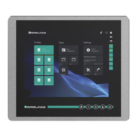
Pepperl+Fuchs VisuNet DPU2100 Series User manual

VisuNet Display Unit
DPU2100-*
PROCESS AUTOMATION
MANUAL

With regard to the supply of products, the current issue of the following document is ap-
plicable: The General Terms of Delivery for Products and Services of the Electrical Indus-
try, published by the Central Association of the Electrical Industry (Zentralverband
Elektrotechnik und Elektroindustrie (ZVEI) e.V.) in its most recent version as well as the
supplementary clause: "Expanded reservation of proprietorship"
VisuNet Display Unit

VisuNet Display Unit
3
1 Introduction................................................................................. 4
1.1 Content of this Document ................................................................... 4
1.2 Target Group, Personnel...................................................................... 4
1.3 Symbols Used ...................................................................................... 5
2 Product Description ................................................................... 6
2.1 Overview ............................................................................................... 6
2.2 Technical Data ...................................................................................... 7
2.3 Marking ................................................................................................. 9
2.4 Dimensions and Type Labels.............................................................. 9
3 Installation................................................................................. 11
3.1 Special Conditions of Use................................................................. 11
3.2 General Installation Requirements ................................................... 11
3.3 Mechanical Installation...................................................................... 12
3.4 Repair and Disposal........................................................................... 13
4 Operation and Configuration................................................... 14
5 Appendix ................................................................................... 21
5.1 Health Monitoring .............................................................................. 21

2018-11
4
VisuNet Display Unit
Introduction
1Introduction
1.1 Content of this Document
This document contains information that you need in order to use your product throughout the
applicable stages of the product life cycle. These can include the following:
■Product identification
■Delivery, transport, and storage
■Mounting and installation
■Commissioning and operation
■Maintenance and repair
■Troubleshooting
■Dismounting
■Disposal
The documentation consists of the following parts:
■Present document
■Instruction manual
■Datasheet
Additionally, the following parts may belong to the documentation, if applicable:
■EU-type examination certificate
■EU declaration of conformity
■Attestation of conformity
■Certificates
■Control drawings
■Additional documents
1.2 Target Group, Personnel
Responsibility for planning, assembly, commissioning, operation, maintenance, and
dismounting lies with the plant operator.
Only appropriately trained and qualified personnel may carry out mounting, installation,
commissioning, operation, maintenance, and dismounting of the product. The personnel must
have read and understood the instruction manual and the further documentation.
Prior to using the product make yourself familiar with it. Read the document carefully.
Note!
This document does not substitute the instruction manual.
Note!
For full information on the product, refer to the instruction manual and further documentation on
the Internet at www.pepperl-fuchs.com.

VisuNet Display Unit
Introduction
2018-11
5
1.3 Symbols Used
This document contains symbols for the identification of warning messages and of informative
messages.
Warning Messages
You will find warning messages, whenever dangers may arise from your actions. It is mandatory
that you observe these warning messages for your personal safety and in order to avoid
property damage.
Depending on the risk level, the warning messages are displayed in descending order as
follows:
Informative Symbols
Action
This symbol indicates a paragraph with instructions. You are prompted to perform an action or
a sequence of actions.
Danger!
This symbol indicates an imminent danger.
Non-observance will result in personal injury or death.
Warning!
This symbol indicates a possible fault or danger.
Non-observance may cause personal injury or serious property damage.
Caution!
This symbol indicates a possible fault.
Non-observance could interrupt the device and any connected systems and plants, or result in
their complete failure.
Note!
This symbol brings important information to your attention.

2018-11
6
VisuNet Display Unit
Product Description
2 Product Description
2.1 Overview
The DPU2100-* display unit is an ATEX/IECEx certified device intended for use in potentially
explosive atmospheres such as Zones 1/21.
Connected to a Pepperl+Fuchs thin client unit or PC unit, the DPU serves as a display with an
optional touchscreen. It enables users to perceive the system outputs of the computing unit
and input user data.
Five system keys on the front of the unit allow users to control system functions (e.g.,
brightness) and the computing unit (e.g., home key). Integrated signal lights on the front keys
show selected failure modes in case of a defective component.
The display unit is optimized for use with the modular HMI components of the VisuNet product
line: TCU1100-* thin client unit, PCU1100-* PC unit, and PSU1100-* power supply unit.
Note!
For a description of the product model nomenclature, view the DPU2100-J1-19U* product
datasheet on www.pepperl-fuchs.com.

VisuNet Display Unit
Product Description
2018-11
7
2.2 Technical Data
Note!
Environmental Conditions
This equipment is designed for indoor/outdoor use at a maximum altitude of 2000 m.
Supply
Power dissipation 25 W
Power consumption average: 24 W
at maximum brightness: max. 25.2 W
Display
Ty p e LC display with LED backlight optically
bonded, thermally hardened glass
Screen diagonal 48.26 cm (19 inch)
Resolution 1280x1024 (SXGA) , Aspect ratio 5:4
Color depth 16.7 Mio.
Contrast 1000:1 (typical)
Brightness 1000 cd/m2
Reading angle 170°horizontal , 160°vertical
Life span back lamp life: 70 000 hrs typical half life , at
25 °C (77 °F)
Input devices
Touchscreen optional: projective capacitive, 10 finger multi-
touch, glove-friendly
Control elements 5 capacitive front keys (behind glass):
1 home button, 2 brightness control buttons, 1
touchscreen button, 1 power button
Interface
Interface type interface v1.0 from Pepperl+Fuchs for
computing units from Pepperl+Fuchs
Directive conformity
Electromagnetic compatibility
Directive 2014/30/EU EN 61326-1:2013 (industrial locations) ; EN
61000-6-4:2007+A1:2011
RoHS
Directive 2011/65/EU (RoHS) EN 50581:2012-09
Ambient conditions
Operating temperature -20 ... 60 °C (-4 ... 140 °F)
Storage temperature -20 ... 60 °C (-4 ... 140 °F)
Relative humidity 93% at 40°C, non-condensating, according to
EN 60068-2-78
Shock resistance 3 shocks 20 g , 11 ms all axis, IEC 60068-2-27
Vibration resistance 5 ... 500 Hz, +/- 0.075 mm , 1.5 g, 10 cycles
per axis according to EN60068-2-6
Mechanical specifications
2018-11
8
VisuNet Display Unit
Product Description
Degree of protection IP66
Material
Surface front: glass with powder-coated aluminum
(6061) bezel
back: powder-coated aluminum
Mass approx. 14.5 kg
Dimensions 542 mm x 460 mm x 48 mm
Data for application in connection with hazardous areas
EU-Type Examination Certificate CML 17 ATEX 5191X
Marking II 2G Ex eb ib q IIC T4 Gb
II 2D Ex tb IIIC T85 °C Db
Directive conformity
Directive 2014/34/EU EN 60079-0:2012+A11:2013, EN 60079-
5:2015, EN 60079-7:2015, EN 60079-
11:2012, EN 60079-31:2014
International approvals
IECEx approval IECEx CML 17.0106X
Approved for Ex eb ib q IIC T4 Gb
Ex tb IIIC T85 °C Db
Standards IEC 60079-0:2011, IEC 60079-5:2015, IEC
60079-7:2015, IEC 60079-11:2011, IEC
60079-31:2013

VisuNet Display Unit
Product Description
2018-11
9
2.3 Marking
ATEX/IECEx Marking
2.4 Dimensions and Type Labels
Dimensions
Figure 2.1 VisuNet DPU2100-* dimensions
Display Unit
DPU2100-*
Pepperl+Fuchs GmbH
Lilienthalstraße 200, 68307 Mannheim, Germany
ATEX: CML 17 ATEX 5191X
II 2G Ex eb ib q IIC T4 Gb
II 2D Ex tb IIIC T85 °C Db
IECEx: IECEx CML 17.0106X
Ex eb ib q IIC T4 Gb
Ex tb IIIC T85 °C Db
Note!
FCC Digital Devices Statement
This equipment has been tested and found to comply with the limits for a Class A digital device,
pursuant to part 15 of the FCC Rules. These limits are designed to provide reasonable
protection against harmful interference when the equipment is operated in a commercial
environment. This equipment generates, uses, and can radiate radio frequency energy and, if
not installed and used in accordance with the instruction manual, may cause harmful
interference, in which case the user will be required to correct the interference at his own
expense.
48
419
65
382
542
460

2018-11
10
VisuNet Display Unit
Product Description
Labels
The following labels are present on the display unit.
Type label display unit
Warning marking
"Warning –Do not open! This enclosure is
factory sealed."
"Avertissement –Cette enveloppe est scellée
en usine. Ne pas l'ouvrir!"
Warning marking
"Warning –Do not open when energized!"
"Warning –Refer to instruction manual!"
"Avertissement –Ne pas ouvrir sous tension!"
"Avertissement –Reportez-vouz au manuel
d'instruction!"
Warning - Do not open!
This enclosure is factory
sealed!
Warning - Refer to
instruction manual!
Warning - Do not open
when energized!

VisuNet Display Unit
Installation
2018-11
11
3 Installation
3.1 Special Conditions of Use
■The DPU must be mated with a suitably certified module, such as a TCU or PCU.
■Connection of TCU/PCU and display shall only be made when de-energized.
■The display does not pose an electrostatic discharge hazard under normal use
conditions. Use only a water damp cloth and allow to air dry for cleaning the device. Do
not use or install in high-charge areas. See IEC 60079-32-1 for further information.
■In hazardous dust environments, regularly remove dust from the display unit to prevent
excessive temperature rise. See certificate for full information.
■The device shall be installed such thatrisk of high-impact energy on display glass is
considered to below.
■The unit type DPU2100-* mayonly be used in connection with Pepperl+Fuchs computer
unit *CU1100-J1-* according to EU-Type examination certificate BVS 16 ATEX E 083X
for ATEX applications or IECEx BVS 16.0060X for IECEx applications. It must be
properly joined prior to being installed into a hazardous environment. See the system
manual for full mounting details.
■Power supplied from the TCU**00-* or PCU**00-* needs to be from a SELV or PELV
source.
3.2 General Installation Requirements
Observe the following requirements when installing the display unit.
■The equipment must be installed by competent personnel in accordance with the
instructions. National laws and regulations must be observed.
■The building installation must provide a 20 A overcurrent protection.
■The installer must make a readily accessible disconnect device available.
■The safety of any system incorporating the power supply unit is the responsibility of the
assembler of the system.
Note!
For detailed installation information, see the VisuNet IXD system manual.
Before installation, take into consideration the compatibility of the materials on
this device and the environment in which the device will be used.

2018-11
12
VisuNet Display Unit
Installation
3.3 Mechanical Installation
Mounting the PCU/TCU onto the DPU
1. Ensure the correct position of the PCU/TCU.
2. Place the PCU/TCU with the Pepperl+Fuchs connector above the Pepperl+Fuchs socket on
the back of the display unit.
3. Carefully push the Pepperl+Fuchs connector into the Pepperl+Fuchs socket.
4. Use the mounting screws to attach the PCU/TCU onto the display unit. Tighten the screws
in a criss-cross pattern to a torque of 2 Nm).
Figure 3.1 Mounting the TCU/PCU onto the display unit
Note!
For system installation instructions and complete mounting options, see the VisuNet IXD
System Manual. Installation to IEC 60079-14 and other local and national requirements are to
be followed as needed.

VisuNet Display Unit
Installation
2018-11
13
Ground Connection
The system must be properly grounded. The display's ground bolt serves as the ground bolt for
the TCU/PCU once the TCU/PCU is mounted to the display.
The ground bolt is on the back of the display unit.The required hardware is included in delivery
with the display unit. The grounding location is marked with a ground symbol:
Observe the following requirements:
■The protective grounding conductor / equipotential bonding conductor shall be the same
size as the power feed, but a minimum of 4 mm2.
■Torque ground hardware to 4 Nm.
3.4 Repair and Disposal
Caution!
Damage to pins
Carefully align the PCU/TCU with the DPU when connecting the units. Mounting or
dismounting the PCU/TCU at an angle can damage the pins.
Note!
The DPU can be dismounted from the PCU/TCU and sent to Pepperl+Fuchs for repair and/or
replacement. For mounting and dismounting instructions, see Chapter 3.3.
The powder filling (Ex q) of the display is not user-serviceable. Send the device to the factory
for repairs,if required.
Disposal
Follow all local and any other requirements for disposing of electronic equipment.
When disposing of any system component, mark VOID across all certification labels.

2018-11
14
VisuNet Display Unit
Operation and Configuration
4OperationandConfiguration
Front Buttons
The DPU2100* provides several system functions via the capacitive front buttons.
The front buttons are embedded in the system and located behind the security glass.
Figure 4.1 Buttons on the front of the DPU2100-* display
Warning!
Warning!
Do not use sharp tools like screw drivers to trigger the front buttons.
Warning!
Warning!
Do not use the display when there are scratches in the front glass.
Button Description
1Home Configurable front button to
call a specified function
2Brightness - Reduce display brightness
(dimmable to 0 %)
3Brightness + Increase display brightness
4Touchscreen Enable/disable touchscreen
(e.g. for cleaning purposes).
If the display unit has no built-
in touchscreen, the
touchscreen button is
disabled.
5Power Configurable power button
(shutdown, restart,
hybernate); button can be
disabled
1 2 3 4 5

VisuNet Display Unit
Operation and Configuration
2018-11
15
Status OFF - Power OFF
LEDs off
Status OFF - Power ON
Power LED solid white
Status OFF -
Power OFF
off off off off off
Status OFF -
Power ON
off off off off on (solid
white)
Power ON -
Touchscreen
ON
on (solid
white)
on (solid
white)
on (solid
white)
on (solid
white)
on (solid
green)
Power ON -
Touchscreen
OFF
on (solid
white)
on (solid
white)
on (solid
white)
on (flashing
white)
on (solid
green)
Power ON -
Display OFF
(Brightness
0%)
on (solid
white)
on (solid
white)
on (flashing
white)
on (solid
white)
on (solid
green)
Sleeping
Mode
off off off off on (flashing
green)

2018-11
16
VisuNet Display Unit
Operation and Configuration
Power ON - Touchscreen ON
■Power LED solid green
■Other LEDs solid white
Power ON - Touchscreen OFF
■Power LED solid green
■Touchscreen LED flashing white
■Other LEDs solid white
Power ON - Display OFF (Brightness 0%)
■Power LED solid green
■"Brightness +" LED flashing white
■Other LEDs solid white

VisuNet Display Unit
Operation and Configuration
2018-11
17
Sleeping
■Power LED flashing green
■Other LEDs off
Brightness Control
The Service controller sets the backlight brightness and controls it directly with the two
brightness buttons
Increasing/Reducing Brightness
1. To increase the display brightness, press the button. Press and hold the button to in-
crease the display brightness faster.
Each single button press increases the display brightness about 10 %. Pressing and
holding the button increases the brightness about 20 % every 0.5 second.
2. To reduce the display brightness, press the button. Press and hold the button to
reduce the display brightness faster.
Each single button press reduces the display brightness about 10 %. Pressing and
holding the button reduces the brightness about 20 % every 0.5 second.
Rebooting the System
To reboot the system, press and hold , and for 5 seconds.
To u c h s c r e e n
In contrast to resistive touchscreens, the 10-point multi-touch capacitive touchscreen behind
security glass does not operate with selective force (like touching the screen with a finger).
The function principle is based on the change of a capacitive field: a small current of electricity
runs across the touchscreen and is measured in the corners of the touchscreen. Touching the
display with a finger or a suitable stylus will change the capacitance of the electrical field. In this
way the exact finger/stylus position can be located on the touchscreen.

2018-11
18
VisuNet Display Unit
Operation and Configuration
Touch Sensitivity
To increase or decrease the sensitivity of the touchscreen, a number of different sensitivity
profiles are available.
This allows adjusting the sensitivity of the touch sensor according to the application
requirements (e.g. for working with gloves).
Increasing/Decreasing Touch Sensitivity by Choosing a Sensitivity Profile
To choose a sensitivity profile, use the VisuNet RM Shell user interface.
(Re-)Calibrating the Touchscreen
To (re-)calibrate the touchscreen, use the VisuNet RM Shell user interface.

VisuNet Display Unit
Operation and Configuration
2018-11
19
Locking and Unlocking Front Buttons
The capacitive front buttons are sensitive to water and moisture. To avoid "false positive" button
triggers in challenging environments, the front buttons can be protected with a lock mechanism
in Service Controller firmware versions 1.3.2.198 and higher.
When the lock mechanism is activated, the operator must first unlock the front buttons via an
unlock pattern.
The lock mechanism can only be enabled via VisuNet RM Shell 5 firmware. This feature is
available in RM Shell 5 versions with an update of 5.0.1.441 or higher.
Locking the Front Buttons via VisuNet RM Shell 5
The default setting of the button lock mechanism is "off."
1. From the main screen of RM Shell 5, change "Operator" to "Administrator."
2. Enter the system settings app by clicking the appropriate icon on the home screen.
3. Navigate to "frontkey settings" on the navigation bar.
4. Enable the keypad lock mechanism.
5. Set the idle time before the automatic locking of the keypad (in seconds) by using the slider
to adjust between 1 and 120 seconds.

2018-11
20
VisuNet Display Unit
Operation and Configuration
Apply/Revert Changes in VisuNet RM Shell 5
If you changed settings, the "Apply Changes" button turns green to indicate changes to the
current settings.
1. To save the changes, click .
The changes have been saved.
2. If you want to discard the changes, click .
The changes have been discarded. The settings have been set back to the last saved
version.
In the enabled keypad lock mechanism, none of the front buttons operates individually, but the
front buttons continue to show the same state as unlocked. The attempt to press a key causes
all LEDs to flash three times. Once home is the only button that lights up, the unlock sequence
can be started.
Unlocking the Front Buttons via VisuNet RM Shell 5
When the keypad lock mechanism is enabled, the front buttons must be unlocked before the
button functions can be used. To unlock the front buttons, an unlock sequence from left to right
on the keypad is required:
1. Press the "home" button when it is illuminated .
2. Press the "decrease brightness" button when it is illuminated .
3. Press the "increased brightness" button when it is illuminated.
4. Press the "touch enable/disable" button when it is illuminated .
5. Press the "power" button when it is illuminated.
If the unlock sequence is performed incorrectly, the process must be started again from the
beginning.
An unsuccessful unlocking sequence is indicated by an animation: all buttons flash twice,
followed by the animation that shows the unlock sequence via the front button LEDs.
If the keypad lock mechanism is activated and any button is pressed except the home button,
the unlock animation is shown.
After the set idle time, the front buttons will be locked again automatically. To signal this, all
LEDs flash three times. To lock the front buttons before the idle time has passed, press and
hold the "touch enable/disable" button until all LEDs are flashing three times.
The locking feature can also be set on startup, or only single buttons can be disabled as
requested. For more information, refer to the latest version of the VisuNet RM Shell 5 manual
on www.pepperl-fuchs.com.
This manual suits for next models
1
Table of contents
Other Pepperl+Fuchs Monitor manuals

Pepperl+Fuchs
Pepperl+Fuchs VisuNet GXP Series User manual

Pepperl+Fuchs
Pepperl+Fuchs DPU1100-J1 Series User manual

Pepperl+Fuchs
Pepperl+Fuchs VBA-2E2A-KE4-ENC/SSI-S User manual

Pepperl+Fuchs
Pepperl+Fuchs VisuNet GXP RM-GXP1100-22F User manual

Pepperl+Fuchs
Pepperl+Fuchs VISUNET GMP DM User manual

Pepperl+Fuchs
Pepperl+Fuchs VisuNet GXP Series User guide

Pepperl+Fuchs
Pepperl+Fuchs KFD2-SR2-Ex2.W.SM User manual

Pepperl+Fuchs
Pepperl+Fuchs VisuNet IND DM5 Series User manual

Pepperl+Fuchs
Pepperl+Fuchs VisuNet GMP DM200 Series User manual

Pepperl+Fuchs
Pepperl+Fuchs DA6-SSI/A-U User manual