Peqlab PerfectSpin 24 R User manual

Refrigerated
Mic
r
ocentrifuge
PerfectSpin 24 R
Serv
i
ce
M
a
nual
Ver.1.0

PerfectSpin 24 R
S
e
rvi
c
e
M
a
n
ual
T
a
ble of Contents
1. Safety Precautions...................................................................1
1
.
1
Op
e
ration
Safety
P
r
ecautions
..............
.
.................
.
...............1
2.
System Description
..................................................................
2
2
.
1.
2.2.
2.3.
2.4.
2.5.
Design
B
l
ock
Diagram
.
.
.
.
.
...............
.
................
.
...............
.
............2
Electrical Component
Specifications...........................................3
PCBs Description
..........................................................................3
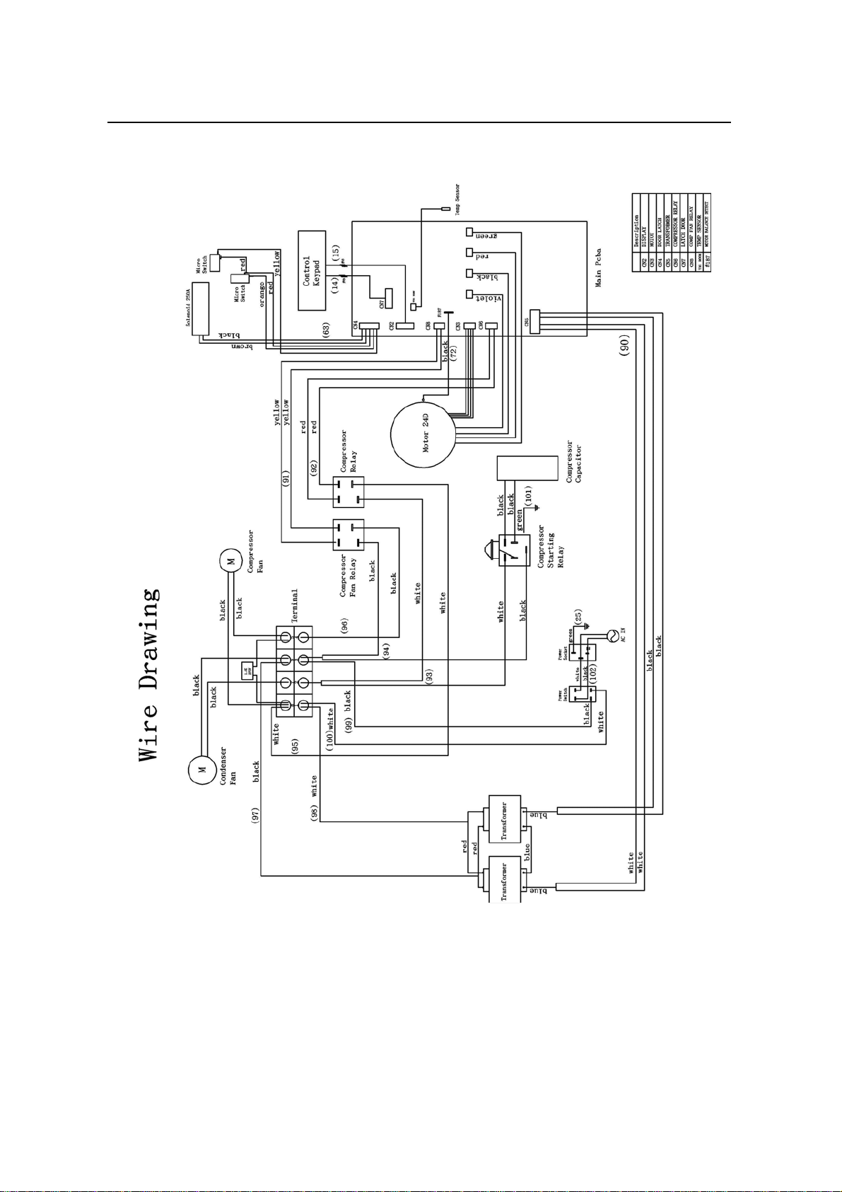
Wire Connection Diagrams
..........................................................4
PCBs Connector Location
............................................................6
2.5.1. Power Board PCB’s Connector Locations.............................................
6
2.5.2. Display/MCU Board PCB’s Connector Locations ................................
8
Refrigeration System
....................................................................8
2
.
6.
3.
T
r
ouble
shooting
.......................................................................
9
3
.
1.
3.2.
3.3.
P
r
oblem
Lis
t
.......
.
..............
.
.
................
.
...............
.
.............
.
............9
Error Messages
............................................................................12
Troubleshooting
Flows
................................................................13
3.3.1. Beeper has no sound
..............................................................................
13
3.3.2. LCD has no display
................................................................................
14
3.3.3. Buttons can’t function
...........................................................................
15
3.3.4. Can’t reach temperature
.......................................................................
16
3.3.5. Can’t reach speed (RPM and RCF) .....................................................
17
3.3.6. Timer can’t count
...................................................................................
17
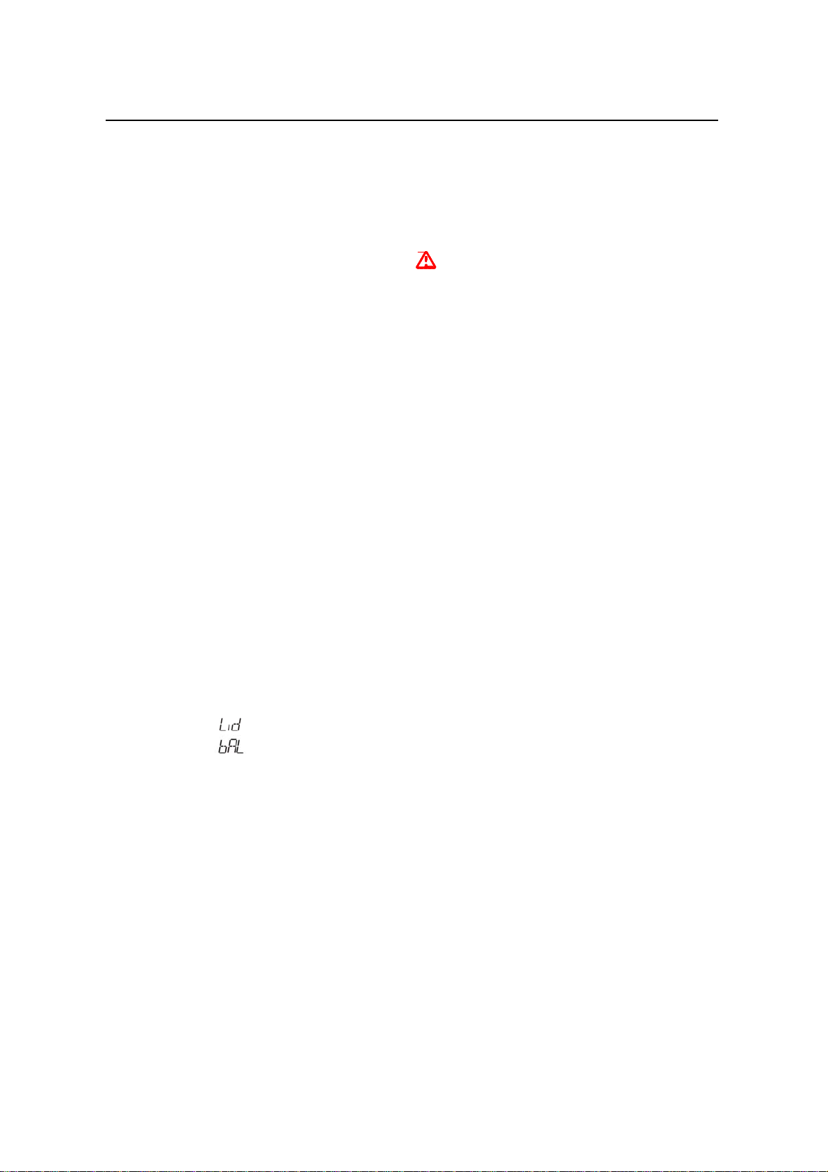
3.3.7. Lid Lock can’t
release............................................................................
18
3.3.8.
“
3.3.9.
“
”
Er
r
o
r
...............
.
......................
.
.......................
.
........................
.
...
19
” Error (Rotor
Imba
l
ance)..........................................................
20
4.
Disassembly/
A
ssembly
...................................................
.......
21
4
.
1.
4.2.
4.3.
4.4.
4.5.
4.6.
4.7.
4.8.
4.9.
4.10.
4.11.
Lid
Cover
Di
s
a
ssembly
......
.
...............
.
...............
.
.............
.
..........21
Top Case Disassembly
.................................................................24
Main Board
Disassembly
............................................................26
Control PCBA
Disassembly........................................................27
Motor Module
Disassembly........................................................28
Solenoid Module
Disassembly
....................................................29
Condenser Fan Module Disassembly
........................................30
Compressor Fan Disassembly
....................................................31
Transformer Modules Disassembly
...........................................32
Relay & Capacitor Modules
Disassembly.................................33
Power Switch Module Disassembly
...........................................34
i

PerfectSpin 24
R
S
e
r
vice
M
anual
ii

PerfectSpin 24 R
Service
Ma
n
ual
1.
Safety
P
r
ecautions
Before servicing the
PerfectSpin 24 R
refrigerated microcentrifuge for the first time,
p
l
ease
read
this entire service manual carefully. It’s also important to refer the operation manual
about
how to operate the unit correctly. For your safety, please observe the following points:
1.1
Operation
Safety
P
r
ecautions
1. When using infectious, radioactive or toxic solutions which may pose health risks,
please observe the appropriate safety precautions.
2. Do not use this machine in a potentially explosive environment or with potentially
explosive chemicals.
3. Install the machine in location free of excessive dust.
4. Avoid placing the machine in direct sunlight.
5. Choose a flat, stable surface capable of withstanding the weight of the machine.
6. Install the machine in the room temperature 15~30°C, relative humidity 20~80%.
7. Do not install the machine in a location that blocks the air vents.
8. Make sure the power source conforms to the required power
suppl
y
specifications.
9. To avoid electric shock, make sure the machine is plugged into a grounded electric
outlet.
10. Do not allow water or any foreign objects to enter the various openings of the
machine.
11. Switch off the power switch before cleaning or performing any service on the
machine, such as replacing the fuses.
12. The rotor and the rotor lid must always be installed securely on the motor
shaft.
13. Always load the rotor symmetrically. Each tube should be counterbalanced
by
another tube of the same type and
weight.
14. To ensure sufficient ventilation, install the centrifuge with at least 30 cm of
free
space on all sides, including the
rear.
15.
Repair should be carried out by Labnet International authorized service personnel
only.
16.
Only use spare parts and accessories provided by Labnet Int. or an authorized Labnet
distributor.
Warning
Label:
Please be aware of the danger of electric shock.
1

2.
S
ystem
Descri
p
t
i
on
2.
S
y
stem
Description
The PerfectSpin 24R is a refrigerated, microprocessor-controlled tabletop
microcentrifuge with rotor speeds up to 13,500 rpm. It is supplied with a 24 x
1.5/2.0
ml rotor for micro samples. The temperature range is from -10 to 40 ºC.
2.1.
Design
Block
Diagram
The unit is equipped with the Display/MCU Board PCB to control the function of lid
open/close, compressor ON/OFF and motor speed, etc. The Power Board PCB which
contains Motor Driver IC and MOSFET is used to supply power and control the brushless
DC induction drive Motor which contains a Hall sensor to detect the motor speed. Other
function controls are shown in Figure 1. Design Block Diagram.
Figu
r
e
1.
Design
Block
Diagram
2

PerfectSpin 24 R
Service
Ma
n
ual
Electrical
Component
Specifications
2.2.
PCBs
Description
2.3.
Pad,
and
E
E
PR
O
M,
etc.
and condenser fan, etc.
3
Parts
Name
Part
Number
Function
D
i
splay/MCU
Board
PCB
193-lrm110-00 Control solenoid lock, LCD display, key
Power
Board
PCB
193-lrm120-00 Control motor, compressor, compressor fan
Parts
Name
Specifications
Temperature
Sensor
(PT-1000)
1 unit,
Platinum, 1,000
Ω
at 0ºC
Condenser
Fan
1 unit,
AC 115V SP101AT/1122HBLGN
( for AC 110V and 100V )
AC 230V DP201AT/2122HBLGN
( forAC 220V )
Compressor
Fan
1 unit,
AC 115V SUNON MA1092-HVLGN
( for AC 110V and 100V )
AC 230V MA2092-HVLGN
( for AC 220V )
Transformer
2 units,
AC 100V PT0760831040
( for AC 100V )
AC 115V PT076060048B
( for AC 110V )
AC 230V PT0760830260
( for AC 220V )
Re
l
ay
2 units, 115V 60Hz/230V 50Hz ( 852-W-1A-C1, DC12V )
Solenoid
l
ock
1 unit, ELM25A112L3
Motor
1 unit, Motor 24D /w kit

2.
S
ystem
Descri
p
t
i
on
2.4.
W
i
r
e
Connection
Dia
grams
The wire connection diagrams are shown in Figure 2. and Figure 3. below. Users can use
these diagrams to understand the connection between the wires and the circuit boards.
Figu
r
e
2.
W
i
r
e
C
on
n
e
c
tion
Diagr
a
m
I
4

PerfectSpin 24 R
Service
Ma
n
ual
Fig
u
r
e
3.
W
i
r
e
Con
n
e
c
tion
Drawi
n
g
II
5

2.
S
ystem
Descri
p
t
i
on
2.5.
PCBs
Connector
Location
The connector locations of Power Board PCB and Display/MCU Board PCB are shown in
Figure 4. and 5. below.
2.5.1. Power
Board PCB
’
s
C
o
n
n
ect
o
r
L
o
c
a
t
i
o
ns
6
Connector
Link
Wire
Part
Number
Application
CN2
Display/MCU
Board CN2 150-r01c10-00
Control signal from
Display/MCU Board.
CN3
Motor Hall Sensor
Cable N/A
Motor Hall Sensor signal from
Motor.
CN4
Solenoid Assembly
150-r01c10-02
Solenoid control signal to
Solenoid Assembly
CN5
Transformer
Module 150-r01c10-04
Supplies power from
Transformer Module.
CN6
Compressor Relay
150-r01c10-11
Control signal to Compressor
Relay.
CN7
Display/MCU
Board CN3 150-r01c10-01
Control signal from
Display/MCU Board.
CN8
Compressor FAN
Relay 150-r01c10-17
Control signal to Compressor
FAN Relay.
TH1
Temp Sensor
150-r01c10-16
Temp Sensor signal to Power
Board.
#187
Balance Detect
150-r01c10-05
Motor Balance Detect from
Motor Module.
PHASE A
Motor BLACK
Cable N/A
Control signal to Motor.
PHASE B Motor RED Cable N/A
Control signal to Motor.
PHASE C
Motor GREEN
Cable N/A
Control signal to Motor.
MOTOR
GND Motor VIOLET
Cable N/A
GND to Motor.

PerfectSpin 24 R
Service
Ma
n
ual
Figu
r
e
4.
Connect
o
r
Loc
ations
of
P
o
w
e
r
Bo
ar
d
P
C
B
7

2.
S
ystem
Descri
p
t
i
on
2.5.2. Disp
l
a
y/
M
CU Board
PCB
’
s Connector
Locations
C
N3
C
N
2
F
i
g
u
r
e
5.
Connect
o
r
Locations
of
Display/MCU
Board
P
C
B
2.6.
Refrigeration
System
The refrigeration system is composed of the following: (1) a compressor, (2) a condenser,
(3) an expansion valve (capillary), (4) a filter/dryer and (5) an evaporator (chamber with
copper coils). Please see Figure 6.
The response time of the compressor is controlled with a microprocessor control. The
microprocessor receives the chamber temperature data through a temperature sensor
located in the bottom of the chamber. Once the pre-set temperature of the chamber is
detected, the compressor will switch off. When the chamber temperature rises above the
pre-set temperature, the compressor will switch on again to cool down the chamber
temperature.
In
opera
t
io
n
,
t
h
e
c
oo
l
air
i
s
ta
k
e
n
in
at
t
h
e
fr
o
nt
of
t
h
e
cent
r
ifuge
by
t
he
con
d
enser
fa
n
,
while the hot air is exhausted at the top of the rear of the machine by the compressor fan.
This air picks up all the heat from the condenser as well as the rotor chamber, the
compressor and the electronics.
The heat of chamber is generated by the fast spinning rotor. The faster the speed is, the
more the heat is generated.
8
Connector
Link
Wire
Part
Number
App
l
ication
CN2
Power Board
CN2 150-r01c10-00
Control signal from
Power Board.
CN3
Power Board
CN7 150-r01c10-01
Control signal from
Power Board.

PerfectSpin 24 R
Service
Manual
The coolant used in PerfectSpin 24 R is R134a which is an environment-friendly
coolant
not
de
p
lete
o
z
o
n
e
.
T
h
e
fill
i
ng
a
m
o
u
n
t
is
86
g
m
.
and does
Fig
u
r
e
6.
R
e
frigeration
S
yst
em
Sch
e
m
e
3.
T
r
oubleshooting
Please refer the following problem and action list to diagnose and resolve the problems.
More troubleshooting flows are described in Section 3.2.
3.1.
P
r
oblem
List
9
Problem
Cause
Action
The display is off even
when power is
switched on.
1. Power is not reaching the
system.
2. Power cord is
not
plugged into the socket
properly.
3. Power fuse is blown out.
1. Check power
source
voltage.
2. Reconnect the powe
r
cord.
3. Replace the power fuse.
4. Return the unit
for
service.

3.
T
r
o
ubles
h
ooting
10
Problem
Cause
Action
Can’t reach pre-set
temperature.
1. Is the pre-set temperature
higher than
the roo
m
temperature, when
the
rotor is not running?
2. Compressor will n
ot
start.
3. Compressor will
star
t,
but can’t reac
h
temperature.
4. The condenser fan
or
compressor fan is not
activated
5. The condenser is dirty.
6. The air inlet and air
outlet are blocked.
1. Reset the pre-
set
temperature to be lower
than the roo
m
temperature.
2. Return the unit f
or
service.
3. Return the unit
for
service.
4. Change the Power Board.
5. Clean the condenser.
6. Remove the blocki
ng
objects of air inlet and air
outlet.
7. Return the unit for
service.
Can’t reach pre-set speed.
( RPM and RCF )
1. The power source voltage
is incorrect.
2. The components
of
Power Board
are
damaged.
1. Check power
source
voltage.
2. Change the Power Board.
3. Return the unit
for
service.
Timer can’t count.
1. Display/MCU board
is
damaged.
1.
Change the
Display/MCU board.
2. Return the unit
for
service.
Lid Lock can’t release.
1. Defective lid lock.
2. No power comes from
Power Board.
3. Centrifuge is
not
receiving power.
4. Lid lock is jammed.
1. Change lid lock module.
2. Change the Power Board.
3. See “The display is off
even when power
is
switched on.”
4. Pull the Emergency Lid
Release Plug.
5. Return the unit
for
service.
Centrifuge can’t start,
although power is on.
1. Lid is not clos
ed
correctly.
2. No speed or time ha
s
been selected.
1. Close lid correctly.
2. Set speed and/or time.
3. Return the unit
for
service.
The buttons has no function.
1. Display/MCU board
is
damaged.
1. Change the
Display/MCU Board.
2. Return the unit
for
service.

PerfectSpin 24 R
Service
Manual
11
Problem
Cause
Action
Centrifuge can’t start.
1. No power supply.
2. Blown fuse.
3. Centrifuge is
not
receiving power.
1. Check power source.
Check the power cord
connection.
Check the power cord
quality.
2. Check the fuse and
replace it, if necessary.
3. See “The display is of
f
even when power
is
switched on.”
4. Return the unit for
service.
No key entry sound.
1. Sound maybe set off.
2. Faulty keys or keypa
d
wiring.
1. Press
“TIME
button” 6
times to check “Beeper”
setting is ON or OFF.
2.
Change the
Display/MCU board.
3. Return the unit
for
service.
The display goes off.
1. Faulty backlight.
2. Faulty LCD panel.
1. Change the
Display/MCU Board.
2. Return the unit
for
service.
Lid will not close.
1. Lid lock is jammed.
1. Change lid lock module.
2. Return the unit
for
service.
Compressor can’t
work.
1. Defective start capaci
tor
or start relay
1. Replace defective s
tart
capacitor or start relay.
2. Return the unit for
service.
Chamber temperature
can’t cool down.
1. Compressor can’t work.
2. Coolant is leaking.
1. Check “Compressor can’
t
work” above.
2. Check and fix coola
nt
leakage spot.
3. Return the unit for
service.
Error message appears.
Refer to list of error
messages below.
Check the nature of the error
and take the suggested
actions.

3.
T
r
o
ubles
h
ooting
Er
r
or
Messages
3.2.
12
Message
Cause
Action
“ ” Error.
1. Press (
START/STOP)
kn
ob
when Lid is open.
2. Defective lid lock sensor.
1. Close the lid.
2. Change Lid loc
k
module.
3. Return the unit for
service.
“ ” Error.
(rotor
imbalance)
1. Tubes are not
inserted
symmetrically in rotor holes.
2. Sample liquid in tubes not properly
balanced.
3. Defective or improperly adjusted
balance sensor.
4. Rotor is stuck when a run starts.
1. Load
tube
symmetrically.
2. Make sure that the
same volume of
liquid
is in each tube.
3. Adjust balance sensor.
4. Change Rotor or Motor.
5. Return the unit
for
service.

PerfectSpin 24 R
Service
Manual
3.3.
T
r
oubleshooting
Flows
Please refer the flows below to analyze the defect problems.
3.3.1. Beeper
has no sound
“Beeper”
function is
turned OFF.
LCD
Display or not?
Yes
No
No
Yes
No
Is AC Power Cable
inserted to the
socket?
Remove
Fuse
Yes
No
Is the fuse
plugged in?
Yes
Yes
Is the fuse
blown?
No
13
Return to vendor for
repair.
Change Fuse.
Plug in Fuse.
Insert the socket.
Turn ON.
Return to vendor for
repair.

3.
T
r
o
ubles
h
ooting
3.3.2. LCD
has no disp
l
ay
Many
reasons
c
o
u
l
d
ca
u
se
LCD
can
’
t
displa
y
.
P
l
ease
follow
the
f
l
ow
below
t
o
anal
y
z
e
t
h
e
possible problems.
Is
AC Power Ca
ble
inserted into th
e
socket?
No
Yes
Is the fuse
plugged in?
No
Yes
Yes
Is the fuse blown?
No
Change
the
Display
/MCU
board.
No
Yes
14
Problem is resolved.
Return to vendor for
repair.
Change Fuse.
Plug in Fuse.
Insert Power Cable into
the socket.

PerfectSpin 24 R
Service
Manual
3.3.3. Buttons
c
a
n’t function
Change
the
Display/
MCU
board.
No
Yes
15
Problem is resolved.
Return to vendor for
repair.

3.
T
r
o
ubles
h
ooting
3.3.4. Can’t
r
e
a
c
h temp
e
r
atu
r
e
Is the
pre-set
temperature higher
than
the room
temperature
when the rotor is
not
running?
Yes
No
No
Compressor can not start?
Yes
No
Compressor will start,
but can’t reach
temperature?
Yes
Inspect whether
the
condenser fan
or
compressor fan
is
activated?
No
Change the Power board.
No
Yes
Yes
Inspect whether
the condenser
is
dirty?
No
Yes
Inspect whether the air
inlet and air outlet
are
blocked?
No
16
Return to vendor for repair.
Remove the blocking objects.
Clean the Condenser.
Return to vendor for repair.
Reset the pre-set temperature
or start the spinning of Rotor.

PerfectSpin 24 R
Service
Ma
n
ual
3.3.5. Can’t
r
e
a
c
h speed (
R
PM and RCF)
No
Is Power source
voltage correct?
Yes
No
Change the
Power board.
Yes
3.3.6.
T
i
mer
can’t count
Change
the
Display/M
CU
board.
No
Yes
17
Problem is resolved.
Return to vendor for
repair.
Problem is resolved.
Return to vendor for
repair.
Use the correct voltage
power source.
Table of contents
Other Peqlab Laboratory Equipment manuals
Popular Laboratory Equipment manuals by other brands

Waters
Waters 717plus Operator's manual

Wassermann Dental-Maschinen
Wassermann Dental-Maschinen KV-16 user manual

Cascade Sciences
Cascade Sciences CVO-5-EX Series Installation & operation manual

cytiva
cytiva Amersham ImageQuant 800 quick start guide

Thermo Scientific
Thermo Scientific Finnpipette F2 Instructions for use

PASCO
PASCO AP-8214 instruction manual

Sri
Sri 8610C GC Installation

Prior Scientific
Prior Scientific OptiScan II ES111 operating instructions

OMEGA AIR
OMEGA AIR EMD Series Installation and operating manual

GYROZEN
GYROZEN 416 Service manual

Datacolor
Datacolor CONDITIONER Operation manual

Metrohm
Metrohm 838 Advanced Sample Processor Technical reference