PerfecTron INS8370A User manual

Version 1.0
INS8370A
Intel® Comet Lake-S 10th Processor with
Q470E/H420E Chipset Mini-ITX
www.perfectron.com

www.perfectron.com
1
Safety Information
Electrical safety
To prevent electrical shock hazard, disconnect the power cable from the electrical outlet before
relocating the system.
When adding or removing devices to or from the system, ensure that the power cables for the
devices are unplugged before the signal cables are connected. If possible, disconnect all power
cables
from the existing system before you add a device.
Before connecting or removing signal cables from the motherboard, ensure that all power cables
are
unplugged.
Seek professional assistance before using an adapter or extension cord. These devices could
interrupt the grounding circuit.
Make sure that your power supply is set to the correct voltage in your area.
If you are not sure about the voltage of the electrical outlet you are using, contact your local
power company.
If the power supply is broken, do not try to fix it by yourself. Contact a qualified service
technician or your local distributor.
Operation safety
Before installing the motherboard and adding devices on it, carefully read all the manuals that
came with the package.
Before using the product, make sure all cables are correctly connected and the power cables are
not
damaged. If you detect any damage, contact your dealer immediately.
To avoid short circuits, keep paper clips, screws, and staples away from connectors, slots, sockets
and
circuitry.
Avoid dust, humidity, and temperature extremes. Do not place the product in any area where it may
become wet.
Place the product on a stable surface.
If you encounter any technical problems with the product, contact your local distributor
Statement
All rights reserved. No part of this publication may be reproduced in any form or by any means,
without prior written permission from the publisher.
All trademarks are the properties of the respective owners.
All product specifications are subject to change without prior notice

www.perfectron.com
2
RoHS Compliance
Perfectron RoHS Environmental Policy and Status Update
Perfectron is a global citizen for building the digital infrastructure. We are committed to
providing green products and services, which are compliant with
European Union RoHS (Restriction on Use of Hazardous Substance in Electronic Equipment) directive
2011/65/EU, to be your trusted green partner and to protect our environment.
In order to meet the RoHS compliant directives, Perfectron has established an engineering and
manufacturing task force to implement the introduction of green products. The task force will ensure that
we follow the standard Perfectron development procedure and that all the new RoHS components and new
manufacturing processes maintain the highest industry quality levels for which Perfectron are renowned.
The model selection criteria will be based on market demand. Vendors and suppliers will ensure that all
designed components will be RoHS compliant

www.perfectron.com
3
Revision History
Revision Date (yyyy/mm/dd) Changes
V1.0 2022/03/10 First release
Packing List
Item
Description Q’ty
1 INS8370A 1
2 CD(Drivier + User’s manual) 1
3 Power Cable 1
If any of the above items is damaged or missing, please contact your
local distributor.

www.perfectron.com
4
Table of Contents
Safety Information .............................................................................................................................................................. 1
Electrical safety .................................................................................................................................................................. 1
Operation safety ................................................................................................................................................................ 1
Statement ......................................................................................................................................................................... 1
RoHS Compliance ................................................................................................................................................................ 2
Revision History .................................................................................................................................................................. 3
Packing List ......................................................................................................................................................................... 3
Chapter 1 : Product Introduction ........................................................................................................................................ 6
1.1 Specifications ............................................................................................................................................................... 6
1.2 Block Diagram .............................................................................................................................................................. 8
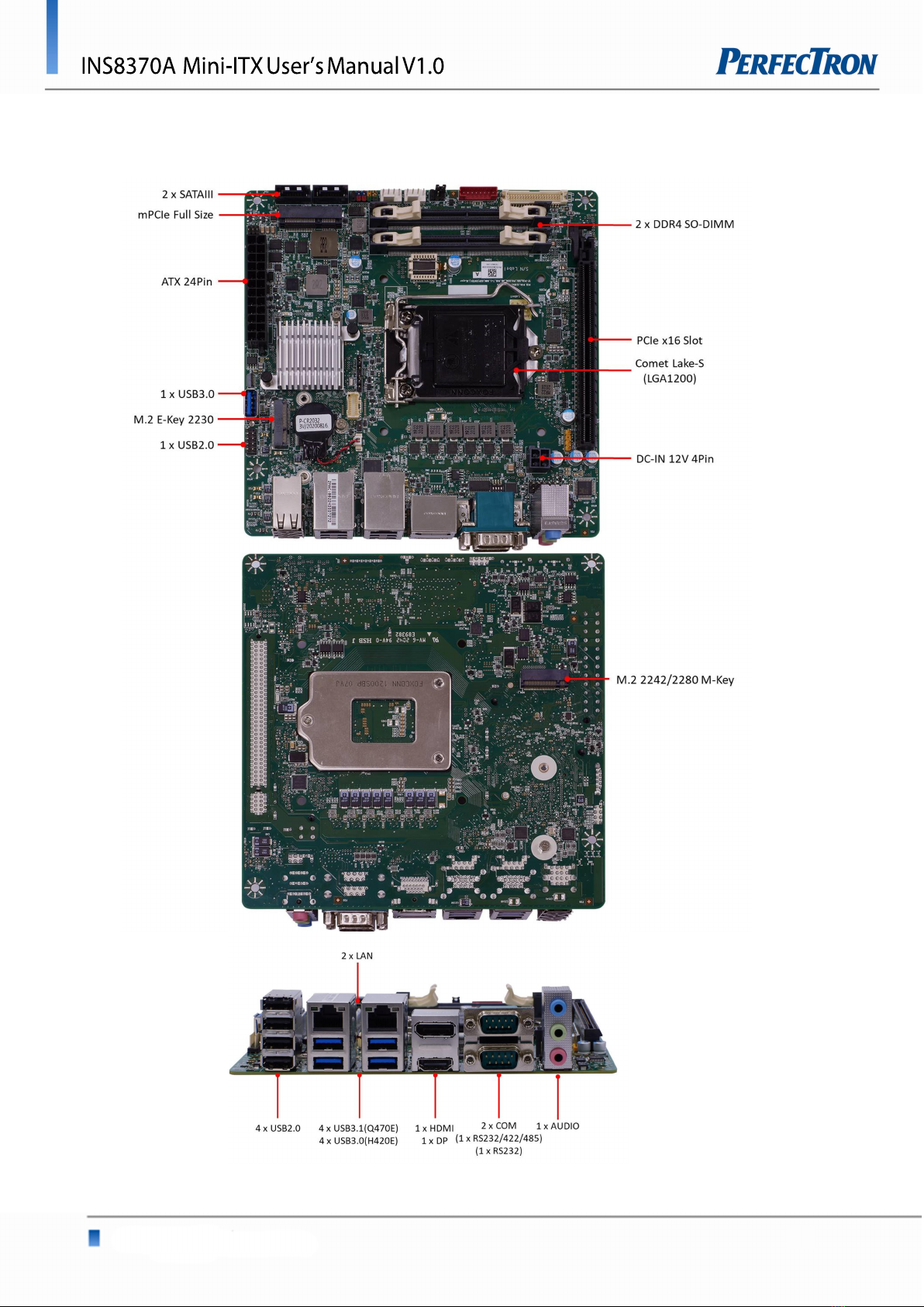
1.3 Board Placement .......................................................................................................................................................... 9
Chapter 2 : Jumpers and Connectors Loacation ................................................................................................................ 10
2.1 Jumpers and connectors list ......................................................................................................................................... 10
2.2 Jumper Settings .......................................................................................................................................................... 11
Chapter 3: AMI BIOS UTILITY ............................................................................................................................................. 16
3.1 Staring ....................................................................................................................................................................... 17
3.2 Navigation Keys .......................................................................................................................................................... 17
3.3 Main Page .................................................................................................................................................................. 18
3.4 Advance Page ............................................................................................................................................................. 20
3.4.1 Onboard Device .................................................................................................................................................. 22
3.4.2 CPU Configuration ............................................................................................................................................... 24
3.4.3 Trusted Computing .............................................................................................................................................. 26
3.4.4 Super IO Configuration ........................................................................................................................................ 27
3.4.5 Serial Port 1 Configuration .................................................................................................................................... 28
3.4.6 Serial Port 2 Configuration .................................................................................................................................... 29
3.4.7 Hardware Monitor ............................................................................................................................................... 30
3.4.8 RTC Wake Settings ............................................................................................................................................... 31
3.4.9 Netword Stack Configuration ................................................................................................................................ 32
3.4.10 NVMe Configuration ........................................................................................................................................... 33
3.4.11 Intel® Rapid Storage Technology .......................................................................................................................... 34
3.5 Event Logs .................................................................................................................................................................. 35
3.5.1 Change Smbios Event Log Settings ......................................................................................................................... 36
3.5.2 View Smbios Event Log .......................................................................................................................................... 37

www.perfectron.com
5
3.6 Security Page .............................................................................................................................................................. 38
3.6.1 HDD Security ........................................................................................................................................................ 39
3.6.2 Secure Boot .......................................................................................................................................................... 40
3.6.3 Key Management(Secure Boot Mode set to Custom) ................................................................................................. 41
3.6.4 BIOS Update ......................................................................................................................................................... 44
3.7 Boot Page .................................................................................................................................................................. 45
3.7.1 (List Boot Device Type) Drive BBS Priorities ............................................................................................................... 48
3.8 Save & Exit Page .......................................................................................................................................................... 49

www.perfectron.com
6
Chapter 1 : Product Introduction
1.1 Specifications
System
CPU 10th Gen Intel® Comet Lake LGA1200 Socket Processor / 10core TDP Max 35W
/ 8ccore TDP 65W / (ATX support 6core 95W)
System Memory DDR4 2933/2666/2400MHz / 2 x 260-pin SO-DIMM / Max. 64 GB (Non-ECC)
Chipset Intel® Q470E (Support RAID 0 / 1 / 5, VPro) / colay H420E
Graphic Intel® HD Graphics
I/O Chipset Nuvoton NCT6126D(eSPI)
TPM Nuvoton NPCT750AAAYX TPM2.0 (Optional)
BIOS AMI BIOS / 256 Mbit SPI
H/W Monitor Temperature Monitor / Voltage Monitor / Fan Monitor
Watchdog Timer 1~255 steps by software program
Smart Fan Control CPU Fan / System Fan
Expansion
M.2 1 x M.2 2230 E key(PCIe / USB)/ M.2 2242 / 2280 M key (PCIeX4, SATA)
Mini PCie 1 x Mini PCIe Full size (PCIe / USB / SATA)
PCIe Slot 1 x PCIe 3.0 X16 slot
Display
HDMI Up to 4K (4096 x 2160) @30 Hz
Displayport Up to 4K (4096 x 2304) @60 Hz
LVDS Up to 1920 x 1200 @60 Hz
eDP (Option) Up to 4K (4096 x 2304) @60 Hz
Ethernet
Chipset Intel® I219-LM Giga LAN + Intel® I210-AT Giga LAN
Audio
Codec Realtek® ALC662 / ALC888
Rear I/O
USB 4 x USB 2.0 / 4 x USB 3.1 (Q470E) ; 4 x USB3.0(H420E)
Display I/O 1 x HDMI 1.4 / 1 x DisplayPort 1.2
Audio I/O 1 x Mic-in / 1 x Line-out / 1 x Line-in

www.perfectron.com
7
Lan I/O 2 x RJ-45
Serial port 2 x RS232 (one support RS422,/485)
Internal I/O
Storage 2 x SATAIII
USB 1 x USB 3.0 / 2 x USB 2.0
Display I/O 1 x LVDS (*Optional eDP SKU available) / 1 x Backlight Connector
GPIO 1 x MiAPI Header (Programmable. Support 10-bit GPIO)
Fan 1 x 4-pin CPU Fan Header / 1 x 4-pin System Fan Header
Power 1 x ATX Power Connector / 1 x AT / ATX Mode Select Jumper /
ATX 12V Power Connector (24-pin + 4-pin)
Others 1 x CMOS Jumper / 1 x Front Audio Header (Mic-in & Line-out) /
1 x panel power select header / 1x buzzer header / 1 x SPDIF
Mechanical and environmental
Form Factor Mini ITX
Power Type ATX 24-pin + 4-
pin / 12V DC (3pin terminal connector via cable by connecting to ATX 24
Dimension 170 mm x 170mm
Operating Temp. ET : -20 ~ 70°C
UT : -40 ~ 85°C
Storage Temp. -40 ~ 85°C
Relative humidity 10% ~ 95% R/H (Non-condensing)
Standard Compliance
Standart Compliance
CE / FCC
OS
OS Support Windows®10 64-bit
Linux(Support by request)

www.perfectron.com
8
1.2 Block Diagram

www.perfectron.com
9
1.3 Board Placement

www.perfectron.com
10
Chapter 2 : Jumpers and Connectors Loacation
2.1 Jumpers And Connectors List
Label
Function
1 Front Audio Header
2 ATX 4pin
3 PCIe x16 Slot
4 DDR4 SO-DIMM Socket
5 LVDS/eDP Connector
6 LVDS Backlight Header
7 Panel Power Option
8 CPU Fan Header
9 System Fan Header
10 Front Pane Header
11 SATA Port
12 Full Size Mini PCIe Slot
13 ATX 24Pin
14 USB3.0 Connector
15 M.2 2230 E-Key
16 USB2.0 Header
17 SPDIF Header
18 CPU Socket
19 RTC Battery header
20 Buzzer Header
21 MiAPI Header
22 Clear CMOS Header
23 AT/ATX Mode Jumper

www.perfectron.com
11
2.2 Jumper Settings
Front Audio Header
PIN
DEFINITION
PIN
DEFINITION
1
MIC
2
AUD_GND
3
MIC_BIAS
4
Presence
5
FP_OUT_R
6
AUD_SENSE_MIC_FP
7
FIO_SENSE
8
Key
(no pin)
9
FP_OUT_L
10
AUD_SENSE_HP
ATX 4pin 12V For CPU
PIN
DEFINITION
PIN
DEFINITION
1 GND 2 GND
3 12V IN 4 12V IN
ATX 24pin
PIN
DEFINITION
PIN
DEFINITION
1
+3.3V
13
+3.3V
2
+3.3V
14
-
12V
3
GND
15
GND
4
+5V
16
PS_ON (low asserted)
5
GND
17
GND
6
+5V
18
GND
7
GND
19
GND
8
PWR_OK(high asserted)
20
-
5V (not used)
9
+5V
Aux
21
+5V
10
+12V
22
+5V
11
+12V
23
+5V
12
+3.3V
24
GND
For single 12V operation both connector 24pin and 4pin are required!
24pin ATX connector :
1. Pin8, 14, 16(NC) must NOT be used in single 12V mode
2. Pin9, 10 , 11 are responsible for the operating mode
3. Pin9: Leave open or connect to 12V. Don’t connect to GND
All four +12Vin pins must be connected to the +12V supply source.
Both GND pins (4-pin conn.) & two GND pins (24-pin connector) must be connected to the
supply source.
Important Note (Single 12V mode):
The “output” pins (3.3Vout, 5Vout, 12Vout) provide power for drives or extra devices.
Maximum “output” power ratings:
+3.3V out: max. 4A = combined output current of 3.3V PCIe x16 and 3.3Vout pins (1, 2, 12, 13)
+5V out: max. 9A = combined output current of all USB ports and +5Vout pins (4, 6, 21, 22, 23)
+12V out: max. 6A depends on output power of single 12V PSU! (12Vout = pin 20)
If the mainboard is off no output voltages are available on the 24 pin ATX connec tor
Note: Each single pin of both connectors is capable of max. 8A!

www.perfectron.com
12
All pins of the 4-pin connector must be used due to peak current in Turbo Mode.
Requirement for Single 12V operation:
IF PIN10 and PIN11 = 12V
&
PIN 9 = open or 12V
only then the mainboard is in Single 12V operating mode.
Single 12V Operation – Cabling Notes
Please use MiTAC suggest cable (3pin terminal connector to 24p ATX + 4pin ATX + SATA power
convert cable (422D83800004)) for single 12V operation. Cable drawing as below:
P1: 3pin terminal connector (Pin1:12v; Pin2:NC; Pin3:GND) for 12V input
P2: 4pin 12V connector for CPU power
P3: 24pin ATX connector
P4: SATA Power
P5: SATA Power

www.perfectron.com
13
LVDS Connector
PIN
DEFINITION
PIN
DEFINITION
1
VCC3
2
Panel Power
3
VCC3
4
Panel Power
5
LVDS_DDC_SCL
6
LVDS_DDC_S
DA
7
GND (CABLE_ID1)
8
GND
9
LVDS0_LINK1_CON_DP
10
LVDS0_LINK0_CON_DP
11
LVDS0_LINK1_CON_DN
12
LVDS0_LINK0_CON_DN
13
GND
14
GND
15
LVDS0_LINK3_CON_DP
16
LVDS0_LINK2_CON_DP
17
LVDS0_LINK3_CON_DN
18
LVDS0_LINK2_CON_DN
1
9
GND
20
GND
21
LVDS1_LINK1_CON_DP
22
LVDS1_LINK0_CON_DP
23
LVDS1_LINK1_CON_DN
24
LVDS1_LINK0_CON_DN
25
GND
26
GND
27
LVDS1_LINK3_CON_DP
28
LVDS1_LINK2_CON_DP
29
LVDS1_LINK3_CON_DN
30
LVDS1_LINK2_CON_DN
31
GND
32
GND
33
LVDS1_CLK_CON_DP
34
LVDS0_CLK_CON_DP
35
LVDS1_CLK_CON_DN
36
LVDS0_CLK_CON_DN
37
GND
38
GND
39
+12V
40
+12V
eDP Connector(Optional)
PIN
DEFINITION
PIN
DEFINITION
1
VCC3
2
Panel Power
3
VCC3
4
Panel Power
5
EDP_CPU_AUXN
6
EDP_CPU_AUXP
7
GND (CABLE_ID1)
8
HPD
9
eDP1_DP
10
eDP0_DP
11
eDP1_DN
12
eDP0_DN
13
GND
14
GND
15
eDP3_DP
16
eDP2_DP
17
eDP3_DN
18
eDP2_DN
1
9
GND
20
GND
21
PCH_BL_EN
22
PCH_BACKLIGHT_PWM
23
NC
24
NC
25
GND
26
GND
27
NC
28
NC
29
NC
30
NC
31
GND
32
GND
33
NC
34
NC
35
NC
36
NC
37
GND
38
GND
39
+12V
40
+12V

www.perfectron.com
14
LVDS Backlight Header
PIN
DEFINITION
1
LVDS_BKTEN_R
2
LVDS_PWM
3
BKLT_PWR (12v)
4
BKLT_PWR (12v)
5
GND
6
GND
7
BRIGHT_UP
-
8
BRIGHT_DOWN
-
Panel Power Option
CPU FAN Header
PIN
DEFINITION
1
GND
2
+12V
3
CPU_FAN_TACH
4
CPU_FAN_CTRL
System FAN Header
PIN
DEFINITION
1
GND
2
+12V
3
System
_FAN_TACH
4
System
_FAN_CTRL
Front Panel Header
PIN
DEFINITION
PIN
DEFINITION
1
Key(no pin)
2
VCC3
3
+12V
4
LCD_VCC_SEL
5 Key(no pin)
6 VCC
3.3V
5V(Default)
12V

www.perfectron.com
15
PIN
DEFINITION PIN
DEFINITION
1
HDD_POWER_LED
2
POWER_LED_MAIN
3
HDD_LED# 4
POWER_LED_ALT
5
GND 6
POWER_SWITCH#
7
RESET_SWITCH#
8
GND
9
+5V_DC 10
Key(no pin)
USB2.0 Header
PIN
DEFINITION
PIN
DEFINITION
1
5V_USB
2
5V_USB
3
Data (negative)
4
Data (negative)
5
Data (positive)
6
Data (positive)
7
GND
8
GND
9
Key (no pin)
10
No Connect
SPDIF Header
PIN
DEFINITION
1
GND
2
SPDIF
-
OUT
3
N/A
4
Power(5V)
MiAPI Header
PIN
DEFINITION
PIN
DEFINITION
1
MAPI_GPIO1
2 VCC
3
MAPI_GPIO
2
4
MAPI_GPIO
6
5
MAPI_GPIO
3
6
MAPI_GPIO
7
7
MAPI_GPIO
4
8
MAPI_GPIO
8
9
MAPI_GPIO
5
10
MAPI_GPIO
9
11
WD_Time
12
MAPI_GPIO
10
13
Power
Button
14
SMBUS_DATA
15
UART_TX
16
SMBUS_CLK
17
UART_RX
18
5VSB
19
GND
20
N/A
Clear CMOS Header
AT/ATX Mode Jumper
PIN
DEFINITION
1-2
Clear CMOS
2-3
Normal(Default)

www.perfectron.com
16
Serial Port Pin-Out
PIN
RS232
RS422
RS485
1
DCD
TX
-
DATA
-
2
RXD#
TX+
DATA+
3
TXD#
RX
-
NC
4
DTR
RX+
NC
5
GND
GND
GND
6
DSR
NC
NC
7
RTS
NC
NC
8
CTS
NC
NC
9
RI
NC
NC
Chapter 3: AMI BIOS UTILITY
PIN
DEFINITION
1-2
AT Mode
2-3
ATX Mode(Default)

www.perfectron.com
17
This chapter provides users with detailed descriptions on how to set up a basic system
configuration through the AMI BIOS setup utility.
3.1 Staring
To enter the setup screens, perform the following steps:
• Turn on the computer and press the <Del> key immediately.
• After the <Del> key is pressed, the main BIOS setup menu displays. Other setup screens
can be accessed from the main BIOS setup menu, such as the Chipset and Power menus.
3.2 Navigation Keys
The BIOS setup/utility uses a key-based navigation system called hot keys. Most of the BIOS
setup utility hot keys can be used at any time during the setup navigation process.
Some of the hot keys are <F1>, <F10>, <Enter>, <ESC>, and <Arrow> keys.
Left/Right The Left and Right <Arrow> keys moves the cursor to select a
menu.
Up/Down The Up and Down <Arrow> keys moves the cursor to select a
setup screen or sub-screen.
+− Plus/Minus
The Plus and Minus <Arrow> keys changes the field value of a
particular setup setting.
Tab The <Tab> key selects the setup fields.
F1 The <F1> key displays the General Help screen.
F10 The <F10> key saves any changes made and exits the BIOS setup
utility.
Esc The <Esc> key discards any changes made and exits the BIOS
setup utility.
Enter The <Enter> key displays a sub-screen or changes a selected or
highlighted option in each menu.

www.perfectron.com
18
3.3 Main Page
Field Name
BIOS Vendr
Default Value American Megatrends
Comment This field is not selectable. There is no help text associated with it.
Field Name
Core
Version
Default Value 5.17
Comment This field is not selectable. There is no help text associated with it
Field Name
Compliancy
Default Value UEFI 2.7 ; PI 1.6
Comment This field is not selectable. There is no help text associated with it
Field Name
BIOS Version
Default Value Display the version of the BIOS
Comment This field is not selectable. There is no help text associated with it
Field Name
Build Date and Time
Default Value Display build date of the BIOS
Comment This field is not selectable. There is no help text associated with it.

www.perfectron.com
19
Field Name
ME FW Version
Default Value ME Firmware Version.
Comment This field is not selectable. There is no help text associated with it.
Field
Name
Processor Information
Default Value Display the installed CPU brand.
Comment This field is not selectable. There is no help text associated with it.
Field Name
Microcode Version
Default Value Display the CPU microcode revision.
Comment This field is not selectable. There is no help text associated with it.
Field Name
Total Memory
Default Value Display the installed memory size.
Comment This field is not selectable. There is no help text associated with it.
Field Name
Memory Slot1
Default Value Display the installed memory size of slot1.
Comment This field is not selectable. There is no help text associated with it.
Field Name
Memory Slot
2
Default Value Display the installed memory size of slot2.
Comment This field is not selectable. There is no help text associated with it.
Field Name
Memory Frequency
Default Value Display the installed memory Frequency
Comment This field is not selectable. There is no help text associated with it.
Field Name
Serial ATA Port 1
Default Value Display the installed SATA device model/size of port 1
Comment This field is not selectable. There is no help text associated with it.
Field Name
Serial ATA Port
2
Default Value Display the installed SATA device model/size of port 2
Comment This field is not selectable. There is no help text associated with it.
Field Name
Serial ATA Port M.2
Default Value Display the installed SATA device model/size of port 3
Comment This field is not selectable. There is no help text associated with it.
Field Name
Serial ATA Port
mSATA
Default Value Display the installed SATA device model/size of port 4
Comment This field is not selectable. There is no help text associated with it.
Table of contents
Other PerfecTron Motherboard manuals

PerfecTron
PerfecTron OXY5363A User manual

PerfecTron
PerfecTron OXY5313A User manual

PerfecTron
PerfecTron INS8365B User manual

PerfecTron
PerfecTron OXY5316A User manual

PerfecTron
PerfecTron OXY5315A User manual

PerfecTron
PerfecTron OXY5638B User manual

PerfecTron
PerfecTron INS8143A User manual

PerfecTron
PerfecTron OXY5737A User manual

PerfecTron
PerfecTron INS8335C User manual

PerfecTron
PerfecTron OXY5320A User manual