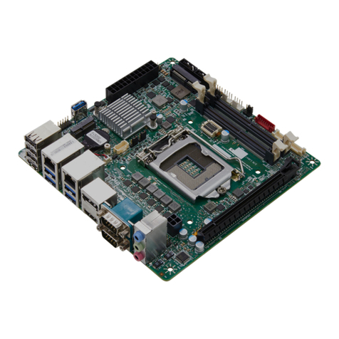
PerfecTron INS8335C User manual

INS8335C User’s Manual V1.1
www.perfectron.com
Safety Information
Electrical safety
To prevent electrical shock hazard, disconnect the power cable from the
electrical outlet before relocating the system.
When adding or removing devices to or from the system, ensure that the power
cables for the devices are unplugged before the signal cables are connected. If
possible, disconnect all power cables from the existing system before you add a
device.
Before connecting or removing signal cables from the motherboard, ensure that
all power cables are unplugged.
Seek professional assistance before using an adapter or extension cord. These
devices could interrupt the grounding circuit.
Make sure that your power supply is set to the correct voltage in your area.
If you are not sure about the voltage of the electrical outlet you are using,
contact your local power company.
If the power supply is broken, do not try to fix it by yourself. Contact a qualified
service technician or your local distributor.
Operation safety
Before installing the motherboard and adding devices on it, carefully read all the
manuals that came with the package.
Before using the product, make sure all cables are correctly connected and the
power cables are not damaged. If you detect any damage, contact your dealer
immediately.
To avoid short circuits, keep paper clips, screws, and staples away from
connectors, slots, sockets and circuitry.
Avoid dust, humidity, and temperature extremes. Do not place the product in any
area where it may become wet.
Place the product on a stable surface.
If you encounter any technical problems with the product, contact your local
distributor
Statement
All rights reserved. No part of this publication may be reproduced in any form or
by any means, without prior written permission from the publisher.
All trademarks are the properties of the respective owners.
All product specifications are subject to change without prior notice
1

INS8335C User’s Manual V1.1
www.perfectron.com
Revision History
Revision Date
(dd.mm.yyyy)
Changes
Version 1.0 27.05.2013 Initial release
Version 1.1 18.09.2013 Add GPIO feature
Packing list
□INS8335C Mini-ITX Industrial MB
□1 x I/O shield
□1 x SATA cable
□2 x COM ports cable w/o bracket
□1 x USB cable
□CD (Driver+ user’s manual)
□Optional Accessories
Cable Kit: LPT Cable
Thermal Kit: CPU cooler
Processor:
a. Intel® Core™ i7-3610QE Processor (6M Cache, 2.30 GHz), 45 W
b. Intel® Core™ i5-3610ME Processor (3M Cache, 2.70 GHz), 35W
c. Intel® Core™ i3-3120ME Processor (3M Cache, 2.40 GHz), 35W
d. Intel® Celeron® Processor 1020E (2M Cache, 2.20 GHz), 35W
If any of the above items is damaged or missing, please contact
your local distributor.
Ordering Information
Part Number Description
INS8335C-ET Mini-ITX Industrial MB Intel® 22nm Ivy Bridge
Processor (Mobile) (-20 to 70°C)
INS8335C-UT Mini-ITX Industrial MB Intel® 22nm Ivy Bridge
Processor (Mobile) (-40 to 85°C optional)
2

INS8335C User’s Manual V1.1
www.perfectron.com
Table of Contents
Safety Information......................................................................................................1
Electrical safety..................................................................................................................1
Operation safety ................................................................................................................1
Statement..........................................................................................................................1
Revision History ..........................................................................................................2
Packing list .................................................................................................................2
Ordering Information..................................................................................................2
Table of Contents ........................................................................................................3
Chapter 1: Product Information...................................................................................6
1.1 Block Diagram ..............................................................................................................6
1.2 Key Features.................................................................................................................7
1.3 Board Placement ..........................................................................................................9
1.4 Mechanical Drawings..................................................................................................10
Chapter 2: Jumpers and Connectors...........................................................................11
2.1 Onboard Connector List ..............................................................................................11
2.2 Jumper Settings and pin assignment ...........................................................................13
SYSFAN2: System FAN2........................................................................................................................ 13
JP9: SYSFAN2_VCC 3.3/5/12V selectable ............................................................................................ 13
JCASE1: Case Open Warning ............................................................................................................... 13
PCIEX1_1: PCI Express x1 .................................................................................................................... 14
PCI1: PCI .............................................................................................................................................. 15
MCARD1: mPCIE/mSATA ..................................................................................................................... 16
BAT1: RTC battery connector .............................................................................................................. 16
DEBUG: Debug card connector ........................................................................................................... 17
AMP1: 4ohm 3Watt Amplifier output pin header............................................................................... 17
AUDIO1: LINE‐OUT/LINE‐IN/MIC‐IN .................................................................................................... 17
MINI_MPCIE: Mini PCIE connector ..................................................................................................... 18
LAN2_USB34: USB3.0 port 3,4 and LAN connector 2 ......................................................................... 19
LAN1_USB12: USB3.0 port 0,1 and LAN connector 1 ......................................................................... 19
COM1: RS232/422/485 and 5/12V selectable .................................................................................... 20
JP5: COM1 +12V/+5V selection........................................................................................................... 20
HDMI: HDMI connector ...................................................................................................................... 20
VGA+DVI: VGA+DVI connector ............................................................................................................ 21
KB_MS1: PS2 Key Board / Mouse ....................................................................................................... 21
ATX_20P: 20 pin ATX Power Input Connector ..................................................................................... 21
ATX12V1: 4 pin ATX Power Input Connector ....................................................................................... 22
LVDS: LVDS connector ......................................................................................................................... 22
JP4: LVDS_VCC 3.3/5/12V selectable .................................................................................................. 22
JBKL1: Inverter connector ................................................................................................................... 23
JP3: BL_EN Level SELECT ..................................................................................................................... 23
JP3: BL_ADJ MODE SELECT.................................................................................................................. 23
SYSFAN1: System FAN1........................................................................................................................ 23
CPUFAN: CPU FAN ............................................................................................................................... 24
3

INS8335C User’s Manual V1.1
www.perfectron.com
DIMMA1: DDR3 SO-DIMM connector................................................................................................. 24
DIMMB1: DDR3 SO-DIMM connector................................................................................................. 24
SIM_CARD: SIM CARD ......................................................................................................................... 24
MSATA_CARD: MSATA ......................................................................................................................... 25
PSON1: ATX/AT mode.......................................................................................................................... 25
COM5: RS232/422/485 and 5/12V selectable .................................................................................... 26
COM6: RS232/422/485 and 5/12V selectable .................................................................................... 26
COM4: RS232 ...................................................................................................................................... 26
COM3: RS232 port 5/12V selectable................................................................................................... 26
JP7: COM3 +12V/+5V selection........................................................................................................... 26
COM2: RS232 port 5/12V selectable................................................................................................... 27
JP6: COM2 +12V/+5V selection........................................................................................................... 27
LPT1: LPT port pin header ................................................................................................................... 27
MCARD_SEL1: mPCIE/Msata selectable.............................................................................................. 27
SATA1, SATA2: Serial ATA 3.0 Connector.............................................................................................. 27
SATA3, SATA4: Serial ATA 2.0 Connector.............................................................................................. 28
F_USB2: USB2.0 pin header ................................................................................................................ 28
F_USB1: USB2.0 pin header ................................................................................................................ 28
JCMOS1: RTC Reset ............................................................................................................................. 29
JP2: Flash Descriptor Security Overide/Intel ME Debug Mode........................................................... 29
FP1: Front Panel 1 ............................................................................................................................... 29
AFP1: LINE‐OUT/MIC‐IN ...................................................................................................................... 29
SPDIF1: SPDIF OUT .............................................................................................................................. 29
FP3: LAN LED ....................................................................................................................................... 29
Chapter 3: AMI BIOS UTILITY .....................................................................................30
3.1 Starting ......................................................................................................................30
3.2 Navigation Keys..........................................................................................................30
3.3 Main Menu ................................................................................................................31
3.4 Advanced Menu .........................................................................................................32
3.4.1 ACPI Settings .............................................................................................................................. 33
3.4.2 CPU Configuration...................................................................................................................... 34
3.4.3 SATA Configuration..................................................................................................................... 36
3.4.4 Thermal Configuration ............................................................................................................... 37
3.4.4.1 Platform thermal configuration.......................................................................................... 37
3.4.5 Intel Rapid Start Technology ...................................................................................................... 38
3.4.6 Intel TXT(LT) Configuration......................................................................................................... 39
3.4.7 PCH-FW Configuration ............................................................................................................... 39
3.4.8 Intel Anti-Theft Technology Configuration ................................................................................. 40
3.4.9 AMT Configuration ..................................................................................................................... 41
3.4.10 USB Configuration .................................................................................................................... 42
3.4.11 F81866 Super IO Configuration................................................................................................ 43
3.4.12 F81866 H/W Monitor............................................................................................................... 44
3.4.13 Serial Port Console Redirection................................................................................................ 45
3.4.14 CPU PPM Configuration ........................................................................................................... 46
3.5 Chipset.......................................................................................................................47
3.5.1 PCH-IO Configuration ................................................................................................................. 47
3.5.1.1 USB Configuration .............................................................................................................. 49
3.5.1.2 PCH Azalia Configuration.................................................................................................... 50
3.5.2 System Agent (SA) Configuration ............................................................................................... 51
3.5.2.1 Graphics Configuration....................................................................................................... 52
3.5.2.2 Memory Configuration ....................................................................................................... 53
3.6 Boot Setting ...............................................................................................................54
4

INS8335C User’s Manual V1.1
www.perfectron.com
3.7 Security......................................................................................................................55
3.8 Save and exit..............................................................................................................56
5

INS8335C User’s Manual V1.1
www.perfectron.com
Chapter 1: Product Information
1.1 Block Diagram
6

INS8335C User’s Manual V1.1
www.perfectron.com
1.2 Key Features
Processor & System
CPU Type
Intel® 22nm Ivy Bridge Processor (Mobile) socket
rPGA988
Core™ i7-3610QE 2.3 GHz (6M Cache, 45W)
Core™ i5-3610ME 2.7 GHz (3M Cache, 35W)
Core™ i3-3120ME 2.4 GHz (3M Cache, 35W)
Chipset
Intel® QM77
Memory Type
2 x 204-pin SO-DIMM up to 16 GB dual channel
DDR3 1333/1600 MHz, Non-ECC
BIOS
AMI® UEFI BIOS
Supoer I/O
F81866D
iAMT
iAMT 8.0
Watchdog
1-255 sec. or 1-255 min. software
programmable, can generate system reset
Expansion Slot
1 x PCI
1 x PCIe x1
2 x Mini PCIe (one co-lay mSATA)
1 x mSATA
Display
Chipset
Integrated GFX in Ivy Bridge processor
Onboard VGA
Yes, (Max. resolution 2048 x 1536)
LVDS
Dual channel 24-bit LVDS, Max. 1920 x 1200
Onboard DVI-D
Yes, (Max. resolution 2048 x 1536)
Onboard HDMI
Yes, (Max. resolution 1920 x 1200)
Independent Display
Capability
VGA, DVI-D, HDMI, LVDS
Audio
Codec
Realtek ALC892 High De nition Audio Codec
Ethernet
Chipset
1 x Intel® 82579LM & 1 x Intel® 82574L GbE
WOL
Yes
Boot from LAN
Yes
Rear I/O
VGA
1
DVI-D
1
HDMI
1
Ethernet
2 x RJ45
USB
4 x USB 3.0
Audio
Mic-in, Line-in, Line-out
COM Port
1x RS232/422/485 with 5V/12V selectable
PS/2
1 x keyboard, 1 x mouse
7

INS8335C User’s Manual V1.1
www.perfectron.com
Internal I/O
SATA
2 x SATAIII (6 Gb/s), 2 x SATAII (3 Gb/s)
LVDS
30-pin connector
USB
4 x USB 2.0 ports by pin header
COM
5 x COM ports
COM2~3 ports RS232 with 5V/12V selectable by pin
header
COM4 port supports RS232 by pin header
COM5~6 ports RS232/422/485 by pin header
DIO
16-bit (8 in/8 out)
Fan
1 x CPU fan, 2 x System fan
Parallel Port
2 x 13-pin header
SIM Card Holder
1
Mechanical and Environment
Form Factor
Mini-ITX Industrial MB
Power Type
ATX (20-pin + 4-pin)
Dimension
170 x 170 mm (6.7" x 6.7")
Operating Temp.
-20 to 70°C
Storage Temp.
-20 to 85°C
Relative Humidity
10% to 90%, non-condensing
*All specifications and photos are subject to change without notice.
8

INS8335C User’s Manual V1.1
www.perfectron.com
1.3 Board Placement
9

INS8335C User’s Manual V1.1
www.perfectron.com
1.4 Mechanical Drawings
10

INS8335C User’s Manual V1.1
www.perfectron.com
Chapter 2: Jumpers and Connectors
2.1 Onboard Connector List
Label
Function
SYSFAN2
System FAN2
JCASE1
Case Open Warning
PCIEX1_1
PCI Express x1
PCI1
PCI
MCARD1
mPCIE/MSATA
BAT1
RTC battery connector
DEBUG
Debug card connector
MINI_MPCIE
Mini PCIE connector
AMP1
4ohm 3Watt Amplifier output pin header
AUDIO1
LINE‐OUT/LINE‐IN/MIC‐IN
LAN2_USB34
USB3.0 port 3,4 and LAN connector 2
LAN1_USB12
USB3.0 port 0,1 and LAN connector 1
COM1
RS232/422/485 and 5/12V selectable
HDMI
HDMI
VGA+DVI
VGA+DVI
KB_MS1
PS2 Key Board / Mouse
ATX_20P
20 pin ATX Power Input Connector
ATX12V1
4 pin ATX Power Input Connector
LVDS
LVDS connector
JBKL1
Inverter connector
SYSFAN1
System FAN1
CPUFAN
CPU FAN
DIMMB1
DDR3 SO-DIMM connector
DIMMA1
DDR3 SO-DIMM connector
SIM_CARD
SIM CARD
MSATA_CARD
MSATA
PSON1
ATX/AT mode
JP9
SYSFAN2_VCC 3.3/5/12V selectable
COM5
RS232/422/485 and 5/12V selectable
COM6
RS232/422/485 and 5/12V selectable
COM4
RS232
COM3
RS232 port 5/12V selectable
COM2
RS232 port 5/12V selectable
JP7
COM3 +12V/+5V selection
JP6
COM2 +12V/+5V selection
LPT1
LPT port pin header
MCARD_SEL1
mPCIE/Msata selectable
SATA1
Serial ATA 3.0 Connector
SATA2
Serial ATA 3.0 Connector
SATA3
Serial ATA 2.0 Connector
SATA4
Serial ATA 2.0 Connector
11

INS8335C User’s Manual V1.1
www.perfectron.com
DIO1
Digital input/output pin header
DIO2
Digital input/output pin header
F_USB2
USB2.0 pin header
F_USB1
USB2.0 pin header
JCMOS1
RTC Reset
JP2
Flash Descriptor Security Overide/Intel ME Debug Mode
FP1
Front Panel 1
AFP1
INE‐OUT/MIC‐IN
SPDIF1
SPDIF OUT
FP3
LAN LED
JP5
COM1 +12V/+5V selection
JP3
BL_EN Level SELECT&BL_ADJ MODE SELECT
JP4
LVDS_VCC 3.3/5/12V selectable
12

INS8335C User’s Manual V1.1
www.perfectron.com
2.2 Jumper Settings and pin assignment
SYSFAN2: System FAN2
Pin
Definition
1
NC
2
SYSFAN2_VCC
3
GND
JP9: SYSFAN2_VCC 3.3/5/12V selectable
Jumper
Function description
Setting
1-2
+3.3V
3-4
+5V
5-6
+12V
Default setting is 1-2
JCASE1: Case Open Warning
Pin
Definition
1
CASE OPEN#
2
GND
13

INS8335C User’s Manual V1.1
www.perfectron.com
PCIEX1_1: PCI Express x1
Pin
Side B Connector
Side A Connector
1
+12V
NC
2
+12V
+12V
3
+12V
+12V
4
GND
GND
5
SMBUS CLOCK
NC
6
SMBUS DATA
NC
7
GND
NC
8
+3.3V
NC
9
NC
+3.3V
10
+3.3VAUX
+3.3V
11
WAKE#
PCIE RESET
Mechanical Key
12
NC
GND
13
GND
PCIE CLOCK+
14
PCIE TXP
PCIE CLOCK-
15
PCIE TXN
GND
16
GND
PCIE RXP
17
NC
PCIE RXN
18
GND
GND
14

INS8335C User’s Manual V1.1
www.perfectron.com
PCI1: PCI
Pin
Definition
Pin
Definition
Pin
Definition
Pin
Definition
A1
Pull down 4.7K to
GND
A32
AD16
B1
-12V
B32
AD17
A2
+12V
A33
+3.3
B2
GND
B33
CBE2#
A3
GND
A34
FRAME#
B3
GND
B34
GND
A4
GND
A35
GND
B4
NC
B35
IRDY#
A5
+5V
A36
TRDY#
B5
+5V
B36
+3.3V
A6
INTA#
A37
GND
B6
+5V
B37
DEVSEL#
A7
INTC#
A38
STOP#
B7
INTB#
B38
GND
A8
+5V
A39
+3.3V
B8
INTD#
B39
LOCK#
A9
GNT1#
A40
SMBUS
CLOCK
B9
NC
B40
PERR#
A10
+5V
A41
SMBUS DATA
B10
REQ1#
B41
+3.3V
A11
NC
A42
GND
B11
NC
B42
SERR#
A12
GND
A43
PAR
B12
GND
B43
+3.3V
A13
GND
A44
AD15
B13
GND
B44
CBE1#
A14
+3.3VAUX
A45
+3.3V
B14
CLOCK1
B45
AD14
A15
RESET#
A46
AD13
B15
GND
B46
GND
A16
+5V
A47
AD11
B16
CLOCK0
B47
AD12
A17
GNT0#
A48
GND
B17
GND
B48
AD10
A18
GND
A49
AD9
B18
REQ0#
B49
M66EN
A19
PCI_PME#
A50
Keyway
B19
+5V
B50
Keyway
A20
AD30
A51
Keyway
B20
AD31
B51
Keyway
A21
+3.3V
A52
CBE0#
B21
AD29
B52
AD8
A22
AD28
A53
+3.3V
B22
GND
B53
AD7
A23
AD26
A54
AD6
B23
AD27
B54
+3.3V
A24
GND
A55
AD4
B24
AD25
B55
AD5
A25
AD24
A56
GND
B25
+3.3V
B56
AD3
A26
AD20
A57
AD2
B26
CBE3#
B57
GND
A27
+3.3V
A58
AD0
B27
AD23
B58
AD1
A28
AD22
A59
+5V
B28
GND
B59
+5V
A29
AD20
A60
REQ64#
B29
AD21
B60
ACK64#
A30
GND
A61
+5V
B30
AD19
B61
+5V
A31
AD18
A62
+5V
B31
+3.3V
B62
+5V
15

INS8335C User’s Manual V1.1
www.perfectron.com
MCARD1: mPCIE/mSATA
Pin
Definition
Pin
Definition
1
-PCH_WAKE
2
+3.3V_MINI
3
NC
4
GND
5
NC
6
+1.5V_PCH
7
NC
8
GND
9
GND
10
UIM_DATA
11
CLK_PCIE_mCARDN
12
UIM_CLK
13
CLK_PCIE_mCARDP
14
UIM_RESET
15
GND
16
UIM_VPP
17
NC
18
GND
19
NC
20
-W_DISABLE1
21
GND
22
-RST_PCIE
23
mCARD_PERN0
24
+3.3V_MINI
25
mCARD_PERP0
26
GND
27
GND
28
+1.5V_PCH
29
GND
30
SMB_CLK
31
mCARD_PETN0
32
SMB_DATA
33
mCARD_PETP0
34
GND
35
GND
36
-USB_MINI
37
GND
38
+USB_MINI
39
+3.3V_MINI
40
GND
41
+3.3V_MINI
42
WWAN_LED#
43
NC
44
WLAN_LED#
45
NC
46
WPAN_LED#
47
NC
48
+1.5V_PCH
49
NC
50
GND
51
NC
52
+3.3V_MINI
BAT1: RTC battery connector
Pin
Definition
1
GND
2
+3.3V
16

INS8335C User’s Manual V1.1
www.perfectron.com
DEBUG: Debug card connector
Pin
Definition
1
33Mhz
2
RST#
3
LFRAME#
4
LAD3
5
LAD2
6
LAD1
7
LAD0
8
+3.3V
9
GND
10
GND
AMP1: 4ohm 3Watt Amplifier output pin header
Pin
Definition
1
SP_OUTL-
2
SP_OUTL+
3
SP_OUTR+
4
SP_OUTR-
AUDIO1: LINE‐OUT/LINE‐IN/MIC‐IN
Pin
Definition
1
LINE-IN
2
LINE-OUT
3
MIC-IN
17

INS8335C User’s Manual V1.1
www.perfectron.com
MINI_MPCIE: Mini PCIE connector
Pin
Definition
Pin
Definition
1
-PCH_WAKE
2
+3VDUAL
3
NC
4
GND
5
NC
6
+1.5V_PCH
7
-CLK_PCIE_MINI_REQ
8
NC
9
GND
10
NC
11
CLK_PCIE_MININ
12
NC
13
CLK_PCIE_MINIP
14
NC
15
GND
16
NC
17
NC
18
GND
19
NC
20
-W_DISABLE1
21
GND
22
-MINI_RST
23
PCIE_RXN_MINI
24
+3VDUAL
25
PCIE_RXP_MINI
26
GND
27
GND
28
+1.5V_PCH
29
GND
30
SMB_CLK
31
PCIE_TXN_MINI
32
SMB_DATA
33
PCIE_TXP_MINI
34
GND
35
GND
36
USB2_PN4
37
GND
38
USB2_PP4
39
+3VDUAL
40
GND
41
+3VDUAL
42
NC
43
GND
44
WLAN_LED1#
45
CL_CLK
46
WPAN_LED1#
47
CL_DATA
48
+1.5V_PCH
49
-CL_RST
50
GND
51
-W_DISABLE_BT
52
+3VDUAL
18

INS8335C User’s Manual V1.1
www.perfectron.com
LAN2_USB34: USB3.0 port 3,4 and LAN connector 2
Upper USB
Lower USB
LAN
Pin
Definition
Pin
Definition
Pin
Definition
1
USBV2
1
USBV3
1
LAN2_MDI0+
2
USBD2-
2
USBD3-
2
LAN2_MDI0-
3
USBD2+
3
USBD3+
3
LAN2_MDI1+
4
GND
4
GND
4
LAN2_MDI1-
5
USB3RN3
5
USB3RN4
5
LAN2_MDI2+
6
USB3RP3
6
USB3RP4
6
LAN2_MDI2-
7
GND
7
GND
7
LAN2_MDI3+
8
USB3TN3
8
USB3TN4
8
LAN2_MDI3-
9
USB3TP3
9
USB3TP4
LAN1_USB12: USB3.0 port 0,1 and LAN connector 1
Upper USB
Lower USB
LAN
Pin
Definition
Pin
Definition
Pin
Definition
1
USBV0
1
USBV1
1
LAN1_MDI0+
2
USBD0-
2
USBD1-
2
LAN1_MDI0-
3
USBD0+
3
USBD1+
3
LAN1_MDI1+
4
GND
4
GND
4
LAN1_MDI1-
5
USB3RN1
5
USB3RN2
5
LAN1_MDI2+
6
USB3RP1
6
USB3RP2
6
LAN1_MDI2-
7
GND
7
GND
7
LAN1_MDI3+
8
USB3TN1
8
USB3TN2
8
LAN1_MDI3-
9
USB3TP1
9
USB3TP2
19

INS8335C User’s Manual V1.1
www.perfectron.com
COM1: RS232/422/485 and 5/12V selectable
Pin
RS-232
RS-422
Half Duplex RS-485
1
COM1_DCD-
TX-
DATA-
2
COM1_SIN
RX+
NA
3
COM1_SOUT
TX+
DATA+
4
COM1_DTR-
RX-
NA
5
GND
GND
GND
6
COM1_DSR-
NA
NA
7
COM1_RTS-
NA
NA
8
COM1_CTS-
NA
NA
9
COM1P9SEL
(Define by JP5)
COM1P9SEL
(Define by JP5)
COM1P9SEL
(Define by JP5)
JP5: COM1 +12V/+5V selection
Pin
Definition
Pin
Definition
1
COM1_RI-
2
COM1P9SEL
3
+5V
4
COM1P9SEL
5
+12V
6
COM1P9SEL
HDMI: HDMI connector
Pin
Definition
Pin
Definition
1
HDMI_2P
11
GND
2
GND
12
HDMI_CLKN
3
HDMI_2N
13
NC
4
HDMI_1P
14
NC
5
GND
15
HDMI_CLK
6
HDMI_1N
16
HDMI_DAT
7
HDMI_0P
17
GND
8
GND
18
+5V
9
HDMI_0N
19
HDMI_DET
10
HDMI_CLKP
20
Table of contents
Other PerfecTron Motherboard manuals

PerfecTron
PerfecTron OXY5638B User manual

PerfecTron
PerfecTron INS8143A User manual

PerfecTron
PerfecTron INS8370A User manual

PerfecTron
PerfecTron OXY5315A User manual

PerfecTron
PerfecTron INS8365B User manual

PerfecTron
PerfecTron OXY5737A User manual

PerfecTron
PerfecTron INS8145A User manual

PerfecTron
PerfecTron OXY5313A User manual

PerfecTron
PerfecTron OXY5320A User manual

PerfecTron
PerfecTron OXY5740C User manual