II. Parts List
Part Part Code Quantity
Travel Trac™Trainer Base....................................A ........................................1
Mag Force Resistance Unit ................................B ........................................1
Knob Bolt ............................................................C ........................................1
Resistance Shift Lever and Cables ....................D ........................................1
Computer Console ..............................................E ........................................1
Pivot Bolt, Washer, Nut ......................................F ........................................1 each
Handle ..................................................................G ........................................1
Locking Ring ........................................................H ........................................1
Axle Support Cups ..............................................I ........................................2
Rubber Feet..........................................................J ........................................4
Rubber Shims for Shift Lever ............................K ........................................2
“AA” Alkaline Batteries ......................................L ........................................2
Quick Release (QR) Skewer................................M ........................................1
5mm Hex Wrench ..............................................N ........................................1
Cable Clips ..........................................................O ........................................2
III.Assembly
1. Remove the trainer, resistance unit and all parts from the box. If you believe
parts are missing, please contact our Technical Support department for assis-
tance at 1-800-727-2453 from 9am to 6pm, EST Monday – Friday.
2. Use the included 5mm hex wrench and a 13mm box wrench or adjustable
wrench to remove the pivot bolt, nut and washer (F) from the frame. See
Figures 2A and 2B.
3. Attach the resistance unit (B) to the trainer base (A) using the pivot bolt, washer
and nut. See Figure 2C. Tighten to a friction fit—enough that the resistance unit
can pivot with some resistance. Position the cable assembly on the left side of
the trainer (when viewed from the rear).
IV.Bicycle Installation
1. Set the Travel Trac™trainer base on a flat, stable surface.
2. Note: Replace the bicycle’s rear wheel quick release (QR) skewer with the one
provided with the trainer. See bicycle owner’s manual for instructions on how
to properly adjust the QR skewer. Make sure the QR skewer is tight and not
damaged or bent.
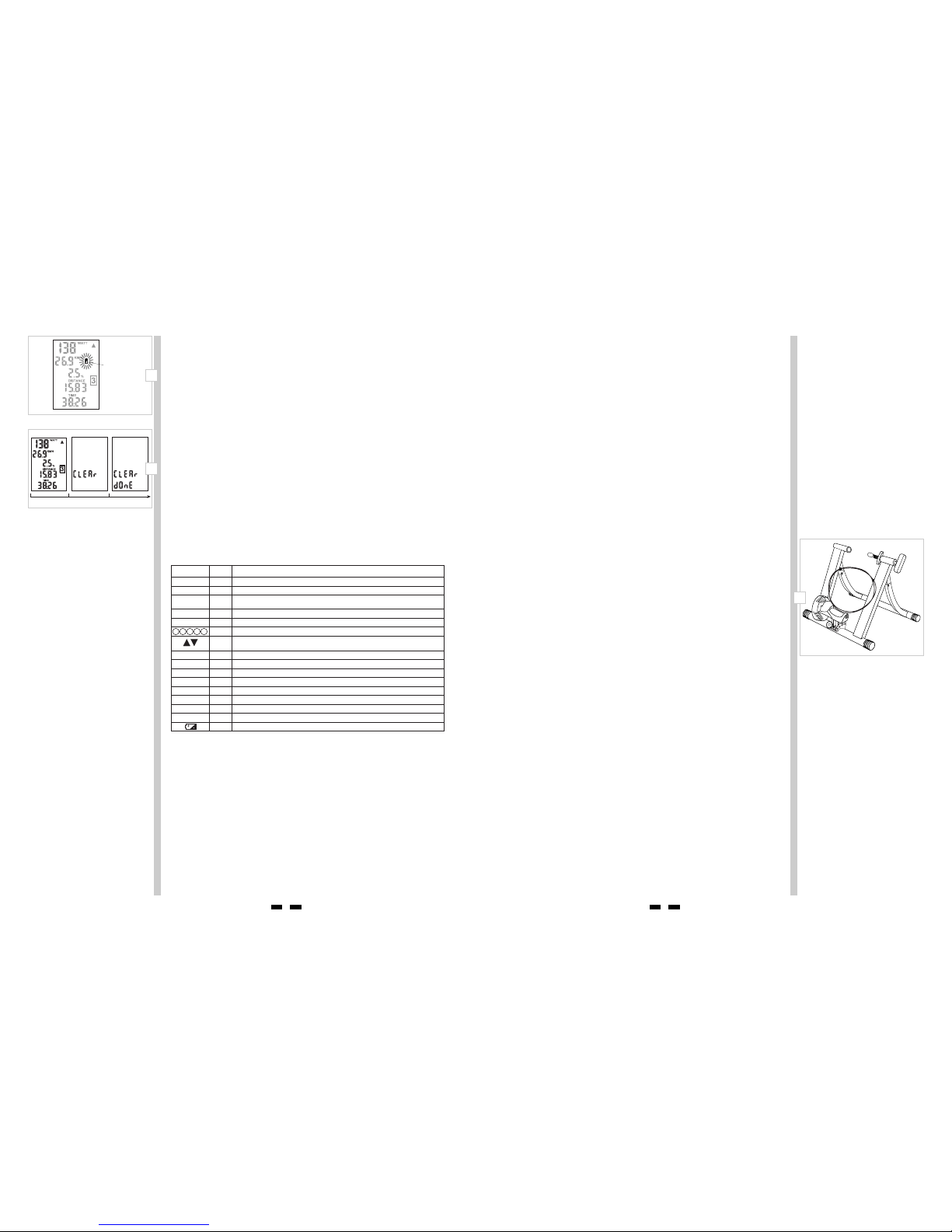
3. Loosen the locking ring (H) by rotating it until it contacts the axle support cup.
See Figure 3.
4. Spin the handle (G) counterclockwise to fully loosen the right side axle support
cup.
5. Loosen the knob bolt (C) by turning it counterclockwise so that the resistance
unit is as close to the floor as possible (to provide clearance for the rear wheel).
6. Lift the bicycle into position, so that the rear QR skewer is aligned with the right
and left axle support cups (I). See Figure 4.
7. Fit the QR skewer lever on the left side of the wheel into the left axle support
cup. Rotate the support cup as necessary, until the notch in the cup is aligned
with the QR skewer lever.
8. Tighten the right side axle support cup against the QR skewer nut on the right
side of the wheel by spinning the handle clockwise until it contacts the QR
skewer nut. Once contact is made, tighten the handle an additional 4-6 rotations.
9. Tighten the locking ring by rotating it until it firmly contacts the trainer base.
See Figure 3.
3
Read and follow all instructions concerning installation of the bicycle on the trainer.
Failure to securely attach the bicycle to the trainer could result in the bicycle
falling, causing injury to the rider or bystanders.
! WARNING
2A
2B
2C
F
B
C
A
G
H
I
J
E
O
1
D
Table of Contents
I. About Your Travel Trac™Mag Force System . . . . . . . . . . . . . . . . . . . . .2
II. Parts List . . . . . . . . . . . . . . . . . . . . . . . . . . . . . . . . . . . . . . . . . . . . . . . . .3
III. Assembly . . . . . . . . . . . . . . . . . . . . . . . . . . . . . . . . . . . . . . . . . . . . . . . . .3
IV. Bicycle Installation . . . . . . . . . . . . . . . . . . . . . . . . . . . . . . . . . . . . . . . . .3
V. Set-Up . . . . . . . . . . . . . . . . . . . . . . . . . . . . . . . . . . . . . . . . . . . . . . . . . . .4
VI. Using Your Travel Trac™Mag Force Trainer . . . . . . . . . . . . . . . . . . . . . .4
A. Screens . . . . . . . . . . . . . . . . . . . . . . . . . . . . . . . . . . . . . . . . . . . .5
B. Battery Life Indicator . . . . . . . . . . . . . . . . . . . . . . . . . . . . . . . . .6
C. Reset . . . . . . . . . . . . . . . . . . . . . . . . . . . . . . . . . . . . . . . . . . . . . .6
D. Auto Off . . . . . . . . . . . . . . . . . . . . . . . . . . . . . . . . . . . . . . . . . . .6
E. Summary List of Ride Data . . . . . . . . . . . . . . . . . . . . . . . . . . . .6
VII. Troubleshooting . . . . . . . . . . . . . . . . . . . . . . . . . . . . . . . . . . . . . . . . . . .6
VIII. Changing the Batteries . . . . . . . . . . . . . . . . . . . . . . . . . . . . . . . . . . . . . .7
IX. Bicycle Removal . . . . . . . . . . . . . . . . . . . . . . . . . . . . . . . . . . . . . . . . . . .7
X. Travel and Storage . . . . . . . . . . . . . . . . . . . . . . . . . . . . . . . . . . . . . . . . .7
XI. Specifications . . . . . . . . . . . . . . . . . . . . . . . . . . . . . . . . . . . . . . . . . . . . .7
Quick-start Instructions (for those who do not like to read instruction manuals)
While the Travel Trac™Mag Force unit is ready to use right out of the box, please
note that the slope and elevation gain information will only be accurate after you
have entered your weight in the Set-Up screen. See section V, “Setup”, for details.
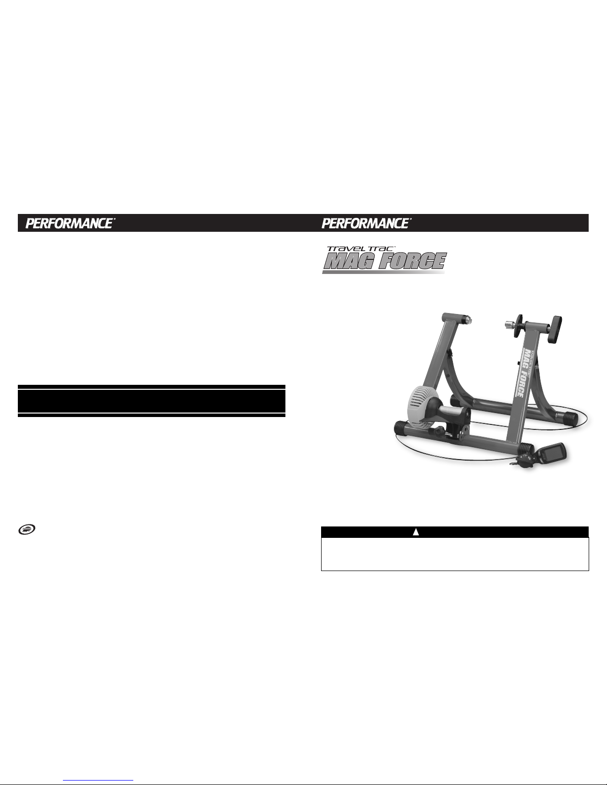
I. About Your Travel Trac™Mag Force System
The Travel Trac™Mag Force system provides a fun, effective workout using your
own bicycle in the comfort of your own home, and can easily be switched from
bike to bike or between riders. Customize your workout as desired, and get the
feedback you need to create a great training program!
Travel Trac™Trainer Base
The Travel Trac™Mag Force resistance unit is mounted to a trainer base constructed
of heavy-gauge powder-coated steel with rubber, shock-absorbing feet to provide a
stable platform for any level of training.
Adjustable Magnetic Resistance Unit
This is a modified version of our popular Mag+ resistance unit, equipped with a
handlebar-mounted shift lever and computer console. The adjustable magnetic
resistance unit provides a wide range of variable resistance, characterized by
smooth, quiet operation. An integrated sensor in the resistance unit sends data to
the computer console mounted on your handlebar.
Handlebar-Mounted Shift Lever
The handlebar shift lever allows on-the-fly selection of 5 resistance levels, which
simulate slope.
Computer Console
The computer console calculates and displays data provided by the resistance unit
sensor. The large LCD screen mounts directly to the handlebar, and presents the
data in an easy to read format.
Functions
The Travel Trac™Mag Force bicycle training system provides the following valuable
training feedback:
Speed: Current, Average, Maximum
Distance: Trip Distance, Total Distance (Odometer)
Time: Ride Time, Total Time
Power: Current, Average, Maximum
Slope (% Grade): Current, Average (Slope is simulated by the level of resistance.
Please note that at any given resistance level Slope will vary
according to rider weight.)
Elevation Gain: To tal Elevation Gain, based on Trip Distance and Slope
2