Motorline professional ZUMA Instruction Manual

v.
REV. /
ZUMAZUMA EN
USER / INSTALLER'S MANUAL

1B
4A
4B
5
6A
6B
7A
18
19
9A
7B
10
12A
11
12B
16A
9B
15
8
13
14
16B
17A
17B
1A 1B
ENEN
. SAFETY INSTRUCTIONS
00. CONTENT
INDEX ATENTION:
01. SAFETY INSTRUCTIONS
This product is certified in accordance with European
Community (EC) safety standards.
This product complies with Directive 2011/65/EU of the
European Parliament and of the Council, of 8 June 2011, on
the restriction of the use of certain hazardous substances in
electrical and electronic equipment.
(Applicable in countries with recycling systems).
This marking on the product or literature indicates that the
product and electronic accessories (eg. Charger, USB cable,
electronic material, controls, etc.) should not be disposed
of as other household waste at the end of its useful life. To
avoid possible harm to the environment or human health
resulting from the uncontrolled disposal of waste, separate
these items from other types of waste and recycle them
responsibly to promote the sustainable reuse of material
resources. Home users should contact the dealer where they
purchased this product or the National Environment Agency
for details on where and how they can take these items
for environmentally safe recycling. Business users should
contact their vendor and check the terms and conditions
of the purchase agreement. This product and its electronic
accessories should not be mixed with other commercial
waste.
This marking indicates that the product and electronic
accessories (eg. charger, USB cable, electronic material,
controls, etc.) are susceptible to electric shock by direct or
indirect contact with electricity. Be cautious when handling
theproductandobserveallsafetyproceduresinthismanual.
STOPS ADJUSTMENT
ADJUST THE SPRINGS
INSTALLATION MAP
CONNECTION SCHEME
INSTRUCTIONS FOR FINAL CONSUMERS / SPECIALIZED TECHNICIANS
SPRING POSITION
FOUNDATION
INSTALLATION OF SPRINGS (ZUMA / ZUMA )
INSTALLATION OF SPRINGS (ZUMA )
BOOM ASSEMBLY (ZUMA / ZUMA )
BOOM ASSEMBLY (ZUMA )
TEST SPRING ADJUSTMENT
AMOUNT OF SPRINGS
AUTOMATISM INSTALLATION
FIXING BOOM SUPPORTS
LIMIT SWITCHES ADJUSTMENT
POWER SUPPLY CABLE
TECHNICAL CHARACTERISTICS
INSTALLATION COMPONENTS
DIMENSIONS
REMOVE THE DOOR
MANUAL OPENING / CLOSING
. AUTOMATISM
. INSTALLATION
. CONNECTIONS
. TROUBLESHOOTING
ADJUSTMENT TABLES

2A EN
GENERAL WARNINGS
•This manual contains very important safety and usage information.
very important. Read all instructions carefully before beginning the
installation/usage procedures and keep this manual in a safe place
that it can be consulted whenever necessary.
•This product is intended for use only as described in this manual. Any
other enforcement or operation that is not mentioned is expressly
prohibited, as it may damage the product and put people at risk
causing serious injuries.
•Thismanual is intendedfirstlyforspecialized technicians, and does not
invalidate the user’s responsibility to read the “User Norms” section in
order to ensure the correct functioning of the product.
•The installation and repair of this product may be done by qualified
and specialized technicians, to assure every procedure are carried
out in accordance with applicable rules and norms. Nonprofessional
and inexperienced users are expressly prohibited of taking any action,
unless explicitly requested by specialized technicians to do so.
•Installations must be frequently inspected for unbalance and the
wear signals of the cables, springs, hinges, wheels, supports and other
mechanical assembly parts.
•Do not use the product if it is necessary repair or adjustment is
required.
•When performing maintenance, cleaning and replacement of parts,
the product must be disconnected from power supply. Also including
any operation that requires opening the product cover.
•The use, cleaning and maintenance of this product may be carried
out by any persons aged eight years old and over and persons whose
physical,sensorialormentalcapacitiesarelower,orbypersonswithout
any knowledge of the product, provided that these are supervision
and instructions given by persons with experienced in terms of usage
of the product in a safe manner and who understands the risks and
dangers involved.
•Children shouldn’t play with the product or opening devices to avoid
the motorized door or gate from being triggered involuntarily.
WARNINGS FOR TECHNICIANS
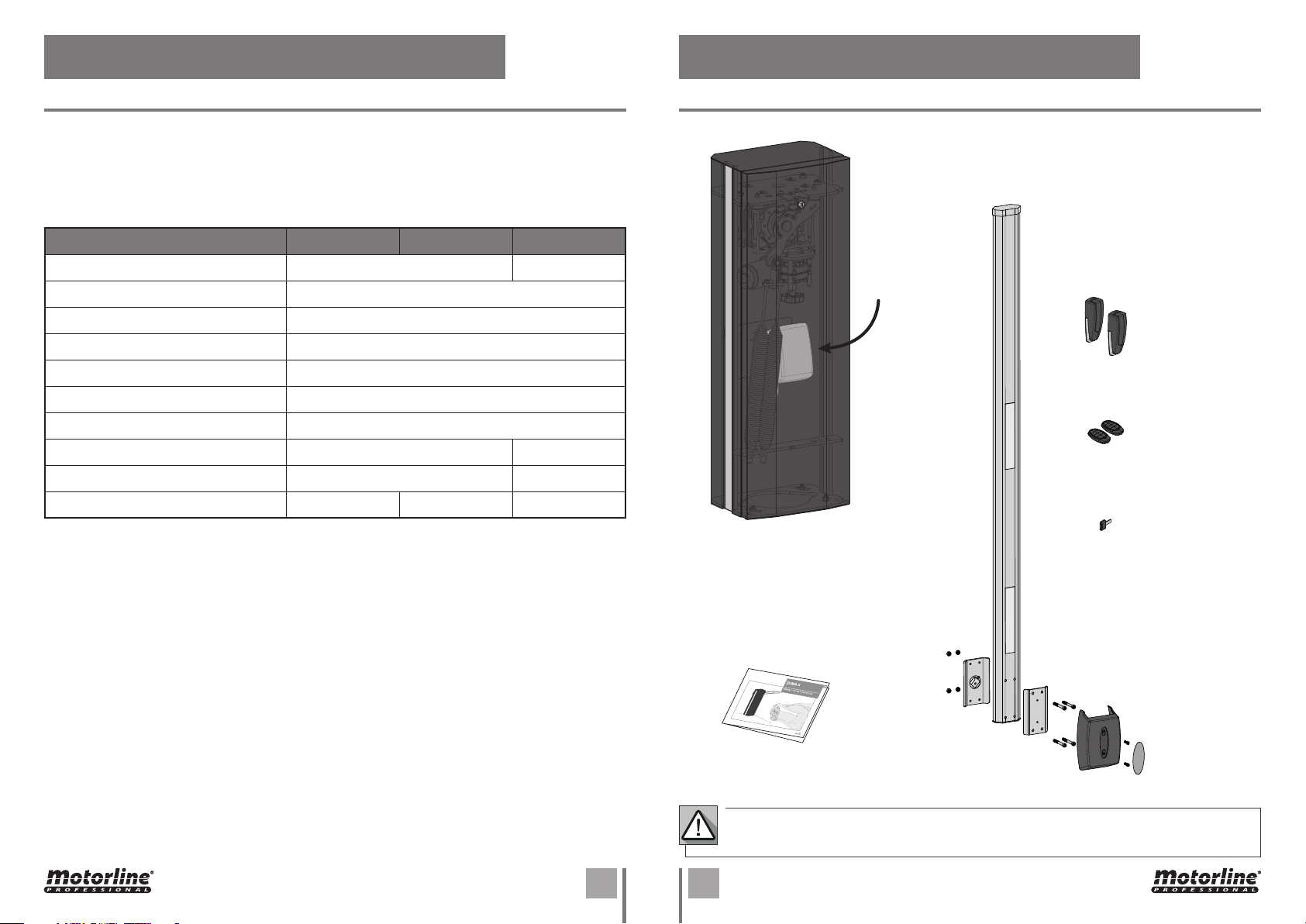
•Before beginning the installation procedures, make sure that you have
all the devices and materials necessary to complete the installation
of the product.
•You should note your Protection Index (IP) and operating temperature
to ensure that is suitable for the installation site.
•Provide the manual of the product to the user and let them know how
to handle it in an emergency.
•If the automatism is installed on a gate with a pedestrian door, a door
locking mechanism must be installed while the gate is in motion.
•Do not install the product “upside down” or supported by elements do
not support its weight. If necessary, add brackets at strategic points
to ensure the safety of the automatism.
•Do not install the product in explosive site.
•Safety devices must protect the possible crushing, cutting, transport
and danger areas of the motorized door or gate.
•Verify that the elements to be automated (gates, door, windows,
blinds, etc.) are in perfect function, aligned and level. Also verify if the
necessary mechanical stops are in the appropriate places.
•The centralmust be installed on asafe placeof anyfluid (rain, moisture,
etc.), dust and pests.
•You must route the various electrical cables through protective tubes,
to protect them against mechanical exertions, essentially on the
power supply cable. Please note that all the cables must enter the
central from the bottom.
•If the automatism is to be installed at a height of more than 2,5m from
the ground or other level of access, the minimum safety and health
requirements for the use of work equipment workers at the work of
Directive 2009/104/CE of European Parliament and of the Council of 16
01. SAFETY INSTRUCTIONS

3A EN
September 2009.
•Attach the permanent label for the manual release as close as possible
to the release mechanism.
•Disconnect means, such as a switch or circuit breaker on the electrical
panel, must be provided on the product’s fixed power supply leads in
accordance with the installation rules.
•If the product to be installed requires power supply of 230Vac or
110Vac, ensure that connection is to an electrical panel with ground
connection.
•The product is only powered by low voltage satefy with central (only
at 24V motors)
WARNINGS FOR USERS
•Keep this manual in a safe place to be consulted whenever necessary.
•If the product has contact with fluids without being prepared, it must
immediately disconnect from the power supply to avoid short circuits,
and consult a specialized technician.
•Ensure that technician has provided you the product manual and
informed you how to handle the product in an emergency.
•Ifthesystemrequiresanyrepairormodification,unlocktheautomatism,
turn off the power and do not use it until all safety conditions have
been met.
•In the event of tripping of circuits breakers of fuse failure, locate
the malfunction and solve it before resetting the circuit breaker or
replacing the fuse. If the malfunction is not repairable by consult this
manual, contact a technician.
•Keep the operation area of the motorized gate free while the gate in in
motion, and do not create strength to the gate movement.
•Do not perform any operation on mechanical elements or hinges if the
product is in motion.
RESPONSABILITY
•Supplier disclaims any liability if:
•Product failure or deformation result from improper installation
use or maintenance!
•Safety norms are not followed in the installation, use and
maintenance of the product.
•Instructions in this manual are not followed.
•Damaged is caused by unauthorized modifications
•In these cases, the warranty is voided.
01. SAFETY INSTRUCTIONS
SYMBOLS LEGEND:
• Important safety
notices
• Useful information
• Programming
information
• Potentiometer
information
• Connectors
information
• Buttons
information

4A 4B
ENEN
02. AUTOMATISM02. AUTOMATISM
Some of these accessories may be sold separately. Consult your distributor.
Automatism technical specifications:
ZUMA is an electromechanical barrier developed to control vehicle access to private, industrial or
commercial areas.
ZUMA 4 ZUMA 6 ZUMA 8
• Operating power 150W 200W
• Barrier Power supply 110/230Vac 50/60Hz
• Motor voltage 24Vdc
• Noise LpA <= 50dB (A)
• Operating temperature -25°C a 55°C
• Protection Level IP55
• Work Frequency 80%
• RPM 3 RPM 2,15 RPM
• Opening / closing time 6 seconds 8 seconds
• Number of springs 1 2 3
• MC60BR Control
board inside
•2 FALK Remote
controls
•Barrier door key
• MF30 photocells
• User manual
• Boom Mounting
Accessories
• Barrier
• Barrier boom
TECHNICAL CHARACTERISTICS INSTALLATION COMPONENTS

5
370mm
220mm 132mm
450mm
370mm 416mm
270mm 300mm
819mm
833mm
1102mm
1131mm
840mm
855mm
100mm
100mm
•
ZUMA / ZUMA
•
ZUMA
EN
02. AUTOMATISM
DIMENSIONS

2
3
4
1
2
6A 6B
ENEN
02. AUTOMATISM 02. AUTOMATISM
In case of an emergency or during the installation/adjustment phase of the barrier, it may be
necessary to move the boom manually. To manually open/close the barrier, follow the instructions
below:
MANUAL OPENING / CLOSING
1
2
3
4
Under no circumstances should you place
your hands on the motor movement axis and
springs when the automation is connected to
the power supply.
REMOVE THE DOOR
Remove the barrier door to access the interior (see
page A).
UNLOCK THE BARRIER
With the barrier locked, push the crank in, turn
to the left and release so that the crank lowers to the
unlocked position.
UP/DOWN BOOM
With the motor in the unlocked position, simply
turn the crank to raise or lower the boom.
BLOCK THE BARRIER
With the barrier unlocked, push the crank in, turn
to the right and release so that the crank lowers to
the locked position.
REMOVE THE DOOR
UNLOCK THE DOOR
Insert the key into the outer lock and turn it
to unlock the door.
This barrier allows free access to the interior, to facilitate the installation and maintenance process of
the product. To do this, you must remove the front door.
REMOVE THE DOOR
Carefully slide the door up to separate it from
the barrier body.
1
2
Slide the door in a movement parallel
to the barrier body so as not to cause
deformations/bends on the parts.

1
2
3
1
2
1
3
11
9
8
13
14
5
2
4
15
7
6
12
10
AB
7A 7B
ENEN
03. INSTALLATION 03. INSTALLATION
INSTALLATION MAP FOUNDATION
Make a hole 400mm (or greater) in depth
and with the following measurements:
ZUMA 4 | ZUMA 6: 370(A) x 470(B)mm
ZUMA 8: 400(A) x 550(B)mm
Fill with concrete and smooth the top.
Apply the barrier to the foundation, with
the fixing bolts in place, to ensure they are
securely secured (see page 8A).
• CREATE FOUNDATION
• EXISTING FOUNDATION
Position the barrier on the foundation to
mark the holes.
Make the markings in the center of the
holes as in the image below.
*If you already have a foundation created, proceed as follows:
1
Remove barrier and drill holes.
Position the barrier and secure it using the
indicated dowels and screws (not included
in the kit).
2
3
1
2
3
Use rigid and/or flexible tubs, suitable for the installation of electrical cables.
Always separate low voltage cables from 230Vac cables to avoid any interference.
The map shown is for a standard installation, however we do not provide all components (see
kit composition on page 4B). If you need other accessories please contact us.
Some of these components can be sold
separately. Consult your distributor.
1 • ZUMA
2 • Front door
3 • Boom
4 • Photocell support column
5 • Photocell
6 • Primary gearmotor
7 • Secondary gearmotor
8 • Motor 24V
9 • Manual movement crank
10 • Control board
11 • Transformer
12 • Spring(s)
13 • Spring support plate
14 • Fixing plate
15 • Fixed boom support

8
2
2
1
34
4
3
EN
03. INSTALLATION
AUTOMATISM INSTALLATION
This adjustment should only be made when the cement of the foundation is dry in order
to avoid displacement of the barrier.
CEMENT MUST BE FRESH IN
STEP 3
Assemble the nuts and bolts in the center of the
holes in the base of the barrier as shown in the
drawing.
With the cement still fresh, apply the barrier so
that the bolts and the nuts go into the cement
at least 65mm.
*If you are installing the engine on an existing
foundation, fix the barrier using screws and
dowels as shown on page 7B (not supplied in the
kit).
Check that the foundation is perfectly level
before applying the barrier.
Pass the electrical cables to connect the motor
to accessories and power. Leave cables with
a length that ensures an easy connection to
the control board (positioned at half the total
height).
1
3
2
4
Min. 65mm Min.
40mm
• ADJUST BARRIER POSITION
*Once fixed to the ground, the ZUMA is prepared to allow a position adjustment of a few
millimeters. Adjustment is made by rotating the barrier in relation to its center.
Give some slack to the tightening nuts of
the plate in order to be able to rotate the
barrier.
Rotate the barrier to the right or left to
place it at the desired point.
Re-tighten the nuts to secure the barrier in
the defined position.
1
2
3

9A 9B
ENEN
03. INSTALLATION 03. INSTALLATION
SPRING POSITION AMOUNT OF SPRINGS
If you order ZUMA without specifying the position of the boom, it will be mounted on the right
(DX).
If the boom is not in the desired position, follow the instructions on page 10 to reverse the
opening/closing direction.
ADJUSTMENT:
• 2xM8 on top (rod end plate)
• 1xM8 at the bottom (structure
plate)
FIXED SUPPORT:
• 2xM16 at the bottom (structure
plate)
• 1xM16 on top (rod end plate)
ADJUSTMENT:
• 2xM8 on top (rod end plate)
FIXED SUPPORT:
• 2xM16 at the bottom (structure
plate)
ADJUSTMENT:
• 1xM8 at the bottom (structure
plate)
FIXED SUPPORT:
• 1xM16 on top (rod end plate)
• Springs installed on the left side• Springs installed on the right side
• BOOM ON THE LEFT (SX) • ZUMA 8 (3 SPRINGS) • ZUMA 6 (2 SPRINGS)• BOOM ON THE RIGHT (DX) • ZUMA 4 (1 SPRING)

10
1
1
2A B C
3
6
4
6
5
5
EN
03. INSTALLATION
INSTALLATION OF SPRINGS (ZUMA 4 / ZUMA 6)
• MOVE SPRINGS
• REMOVE THE SPRINGS FROM THE LEVER
• CHANGE FROM 2 TO 1 SPRING
• REVERSE MOTOR CONNECTIONS
Loosen the nut from the screw on the rear of the
lever.
Remove the fixation plate, unscrewing the nuts that join
the springs and the rod end.
At the end of the operation, check the
wiring connections from the motor to
the control board (see page 18).
Remove the screw and nuts that fix the spring's rod
end to the lever.
Choose only one spring and reverse its position: M16 shaft
up and M8 shaft down.
Position the spring rod end on the other side of the lever
and insert the nuts and the spring fixing screw. Place the
nut from behind and tighten.
Thread the M16 shaft of the spring directly into the rod-end
lever.
Install the spring in the same way as in the previous steps,
but this time with the M8 shaft down, securing to the
structure.
Change the side of the control board so that it is installed
on the opposite side to the springs.
This facilitates access to electronics.
Attach the springs to the lower plate, through the nuts.
When fixing the rod end, place it in the appropriate
hole for the size of the boom you are going to use
(see table on page 15).
Before starting to remove the springs, make sure that:
• The spring side of the lever is all the way down;
• Springsarecompletelyoutofadjustment(no tension).
2
A
7
3
B
4
C
D
5
6
If the springs are on the wrong side for the intended boom direction (see diagram on page
9A), you must reverse the position of the springs on the rotation lever.
To do this, you will have to:
1 · Unscrew the springs from the two support points;
2 · Re-tighten them on the opposite side, respecting the adjustment table on page 15.
*If, due to the size of your boom, there is a need to remove a spring,
proceed as follows:
Unscrew the adjustement nuts (bottom) and remove
the spring bolts from the holes.
1

11
3
2
1
A
B
B
EN
03. INSTALLATION
BOOM ASSEMBLY (ZUMA 4 / ZUMA 6)
Fit the boom cover and secure it with two screws
Apply the sticker to hide the screws.
Fit the remaining pieces in the order shown in the image.
Fasten the parts to the rod fixing plate with screws and
bolts provided in the package.
A • Fit the boom support taking into account the
information presented in the board on the left.
B • Tighten the side screws to secure the support to the
shaft.
2
1
3
• CHECK BOOM SUPPORT POSITION
B • Refit the support on the shaft, this time in the vertical
position;
A • Loosen the screws on the boom support and disengage from
the shaft;
C • Tighten the two screws to secure.
If the springs are up (stretched), you can lower them
using the hand crank (see page 5B)
If this situation does not occur, the boom support must be rotated:
• Vertical plate
Before assembling the boom, check that:
• Springs are down (no tension)
• The boom support is on vertical position

1
1
2
3
6
6
5
5
3
2
1
1
A
B
B
12A 12B
ENEN
03. INSTALLATION
INSTALLATION OF SPRINGS (ZUMA 8) BOOM ASSEMBLY (ZUMA 8)
Follow the instructions indicated on page 10 and making the association with the numbers in the
drawing below, proceed with the installation of the springs in the ZUMA 8. Follow the instructions indicated on page 11 and making the association with the numbers in the
drawing below, proceed with the assembly of the boom in the ZUMA 8.
03. INSTALAÇÃO

13
1
2
3
4
56
78
50mm
EN
03. INSTALLATION
FIXING BOOM SUPPORTS
You must now establish the length of it so that you can then place the support, as shown in the
image below.
The boom must exceed the position of the support arm by 50mm.
After placing the boom with the desired length, secure it
with the two self-tapping screws on the fixed part of the
boom.
Once the length of the boom is established, define the location of
fixing the boom support to the ground.
If the height of the support arm is out of step with the height of the boom, you will need to adjust the
height of the arm. To do this, follow these steps:
Drill two holes at the installation site to secure the support with
screws and dowels.
Loosen the locking stud of the support arm with a hex wrench.
Frame the support holes in the screws already placed and
tighten with the nuts.
Raise or lower the arm to place the support at the height needed to support the barrier.
Attach the nuts' protective caps.
Tighten the locking stud of the support arm to lock it in the set position.
If the stud is not enough to lock the support in the desired position, you must use a self-tapping screw
in order to go through the two profiles to lock the height of the support.
• DEFINE EXTENDABLE BOOM LENGTH
• APPLICATION OF BOOM SUPPORT (FIXED)
• ADJUST SUPPORT (FIXED) HEIGHT
4
7
5
8
1
2
3
6

14
3
1
2
7
4 6
4 6
EN
03. INSTALLATION
ADJUST THE SPRINGS
Before adjusting the springs, manually place the boom in the vertical position so that the springs are in
the position of least tension (see page 5B).
Remove the locking nut from the threaded shaft
of each spring, and keep it until the adjustment
is complete.
On the threaded shaft of each
spring, there are two nuts:
Manually, pull the threaded shaft upwards to
keep the spring taut but without tension.
Keeping the spring in this stretched position,
tighten the adjust rod until it touches the plate.
This is the starting position to perform the
spring adjustment.
Hold the threaded shaft with a pliers so that
it does not rotate, and keep tightening the
adjustment female until each spring is stretched
the distance mentioned in the table on page 15.
After the spring(s) are stretched, deactivate the
manual mode and test the balance between the
springs and the boom, taking the test on page
16A.
If the boom does not stay balanced,
tighten or loosen the adjusting nut to
achieve the best possible balance.
After the adjustment of each spring is
complete, tighten the locking nut until it
touches the adjusting nut. This will lock
the adjustment position to ensure that
the springs do not misadjust.
1
2
3
4
5
6
7
Nut for adjusting
Nut for locking
START POSITION
20mm
55mm
ADJUSTMENT 75mm
ADJUSTMENT
MEASUREMENT
ADJUSTMENT
• ADJUSTMENT EXAMPLE
*In this example, a 5.5M BOOM WITH RUBBER AND SPAT is considered, which needs a 55mm
adjustment (see tables on page 15), where the M8 shaft starts 20mm above the support
plate (INICAL POSITION).

15
6000 5500 5000 4500 4000 3500 3000
6000 5500 5000 4500 4000 3500 3000
6000 5500 5000 4500 4000 3500 3000
6000 5500 5000 4500 4000 3500 3000 8000 7500 7000 6500
8000 7500 7000 6500
8000 7500 7000 6500
8000 7500 7000 6500
EN
03. INSTALLATION
ADJUSTMENT TABLES
SINGLE BOOM
Quantity 2 springs 1 spring 1 spring 1 spring 1 spring 1 spring 1 spring
Adjustment 10mm 65mm 55mm 40mm 5mm - -
Hole Hole 2 Hole 1 Hole 1 Hole 1 Hole 2 Hole 2 Hole 2
BOOM WITH RUBBER
Quantity 2 springs 2 springs 1 spring 1 spring 1 spring 1 spring 1 spring
Adjustment 30mm 15mm 70mm 45mm 20mm - -
Hole Hole 2 Hole 2 Hole 1 Hole 1 Hole 2 Hole 2 Hole 2
BOOM WITH SPAT
Quantity 2 springs 2 springs 2 springs 1 spring 1 spring 1 spring 1 spring
Adjustment 40mm 30mm 15mm 65mm 40mm 25mm 1mm
Hole Hole 2 Hole 2 Hole 2 Hole 1 Hole 2 Hole 2 Hole 2
BOOM WITH RUBBER AND SPAT
Quantity 2 springs 2 springs 2 springs 2 springs 1 spring 1 spring 1 spring
Adjustment 25mm 12mm 30mm 15mm 60mm 35mm 10mm
Hole Hole 1 Hole 1 Hole 2 Hole 2 Hole 2 Hole 2 Hole 2
SINGLE BOOM
Quantity 3 springs 2 springs
Adjustment 45mm 30mm 15mm 25mm
Hole Hole 2 Hole 2 Hole 2 Hole 2
BOOM WITH RUBBER
Quantity 3 springs 2 springs
Adjustment 30mm 45mm 30mm 15mm
Hole Hole 1 Hole 2 Hole 2 Hole 1
BOOM WITH SPAT
Quantity 3 springs 2 springs
Adjustment 35mm 45mm 30mm 20mm
Hole Hole 1 Hole 2 Hole 2 Hole 1
BOOM WITH RUBBER AND SPAT
Quantity 3 springs 2 springs
Adjustment 50mm 35mm 50mm 40mm
Hole Hole 1 Hole 1 Hole 2 Hole 1
• LEVER HOLES
Hole 2
Hole 1
Hole 1
Hole 2
• ZUMA 4 / ZUMA 6 BOOM • ZUMA 8 BOOM

FUSE
1
2
16A 16B
ENEN
03. INSTALLATION 03. INSTALLATION
TEST SPRING ADJUSTMENT
Manually place the boom in the phase 1 position. When you let
go of the boom, it should remain stabilized, or rising very slightly.
Place the barrier in phase 2, phase 3, phase 4 and phase 5 and
repeat the test from step 1 in each of the different phases.
With the adjustment, you should be able to reach a state in which
moving the barrier manually, it should remain stable in any
position you drop it.
· If the boom goes down when it is released, tighten each spring
1mm and test again.
· If the boom rises when you release it, loosen each spring 1mm
and test again.
1
2
The motor must remain unlocked to carry out the adjustment test.
PHASE 1
PHASE 5
PHASE 3
PHASE 2
PHASE 4
POWER SUPPLY CABLE
*The power wiring from the ground must be
connected directly to the fuse located at the
bottom of the barrier.
Pass the power cables coming from the ground to
the fuse.
The fuse is located in front of the transformer
fixing plate.
Connect the power cables to the fuse, which in
turn is connected to the electronic control unit.
Connect Ground Wire to the middle connector as in
the picture.
2
1
Ground wire (green and yellow)
Neutral wire (blue)N
N
N
P
P
P Phase wire

1
1
4
2
3
5
3
3
2
17A 17B
ENEN
03. INSTALLATION 03. INSTALLATION
STOPS ADJUSTMENT LIMIT SWITCHES ADJUSTMENT
The ZUMA rotation lever has limit switch micros that allow you to define the end of the opening and
closing operations.
The stops present on the barrier are visible in the image below.
• They consist of adjustment screws (one on each side of the barrier) fixed to the base as well as its
stops.
• Each screw has a locking nut.
Release the Locking Nut from the stop you
want to adjust. Place the boom in a horizontal
position.
Turn the stop on the side you want to adjust
until it touches the lever.
Tighten screws to lock plate in
position.
Place the boom in the desired position:
Horizontal Position - Closing
Vertical Position - Opening
Slightly loosen the screws on the
activation plate, and move it until you
hear the micro activation click.
Test boom movement and make final
adjustments.
Place the boom in the vertical
position, and repeat steps and for
the other activation plate.
Re-tighten the Locking Nuts to lock the stops
in that position.
11
3
3
22
4
4
5
Stop
Follow these steps to adjust the position of the
stops: Follow these steps to adjust the limit
switches:
Blocking Nut
Adjusting Screw
When the opening or closing micro switch is activated, check if the respective LED on the
control board goes out.
These micros must be set to be
activated the instant before the
lever touches the stop.
When the boom opens and closes, the lever must always touch the rubber stops on the
upper barrier plate.
Plate Screws
Activation
Plate
Limit switch
micros
• Place theboom in the horizontal position
and check if the control board LED goes
out when the plate activates the micro.
• Place the boom in a vertical position and
perform the same test.

18
BG R Y
V+
LK LO
V+ FCF0 LE
LS LBLA
ANT
LAMP MOT1
SP
LAMP MOT1
SP
24v
BATT
20V
VAC
1234
+ - COM NC/
NO
1 2
+ -
TX RX
EN
CONNECTION SCHEME ZUMA / ZUMA
04. CONNECTIONS
• MP105 Flashing light
(Opcional)
• ZUMA 4 / ZUMA 6 Barrier
• Transformer
230Vac/115Vac
120W Max.
• Fuse
230Vac: 2A
115Vac: 3A
Blue
Brown
CLOSE
OPENING
• Limit switches
• Security Band
(Optional)
• Photocells
Motor
MC60BR Control board
In case of inversion of the boom, exchange the blue wire with the brown one and the
connections of the limit switches micros.
• MC60 Control board
(Interior of the
barrier)

19
BG R Y
V+
LK LO
V+ FCF0 LE
LS LBLA
ANT
12V+
1 2 3
BI RI
4 5 6
GI RGI SEI
8 97
SEO
1 2
RGOROBO
2 3 4 51
GOV+
LAMP MOT1
SP
24v
BATT
20V
VAC
1234
+ - COM NC/
NO
1 2
+-
TX RX
EN
04. CONNECTIONS
CONNECTION SCHEME - THTSIG15LEDN MODULE (ZUMA 8)
Green
Blue
Brown
Red
• MC60 Control board (Interior of the barrier) • Module THTSIG15LEDN
• Security Band
(Optional)
• LED stripe
• Twilight
sensor
• ZUMA 8 Safe
• Photocells
• Power
supply
Green
Blue
Brown
Red
• Transformer
230Vac/115Vac
120W Max.
• Fuse
230Vac: 2A
115Vac: 3A
• MP105 Flashing light
(Opcional)
This manual suits for next models
3
Table of contents
Other Motorline professional Automatic Barrier manuals
Popular Automatic Barrier manuals by other brands

Aprimatic
Aprimatic PARK 30 PLUS Instructions for installation, use and maintenance

Roger Technology
Roger Technology ACS/BA/60 Instruction and warnings for the installer

Magnetic Autocontrol
Magnetic Autocontrol MPP-112 operating instructions

O&O
O&O NIGHT&DAY.6 Instructions for installation, use and maintenance

FAAC
FAAC B680H manual

SOMFY
SOMFY Home Motion LEVIXO 30 RTS installation instructions