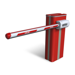
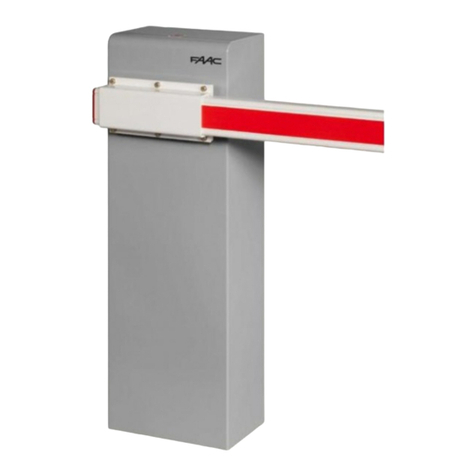
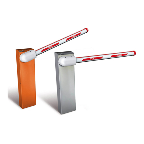
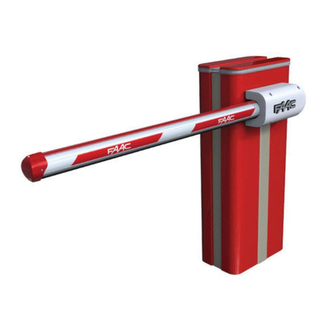
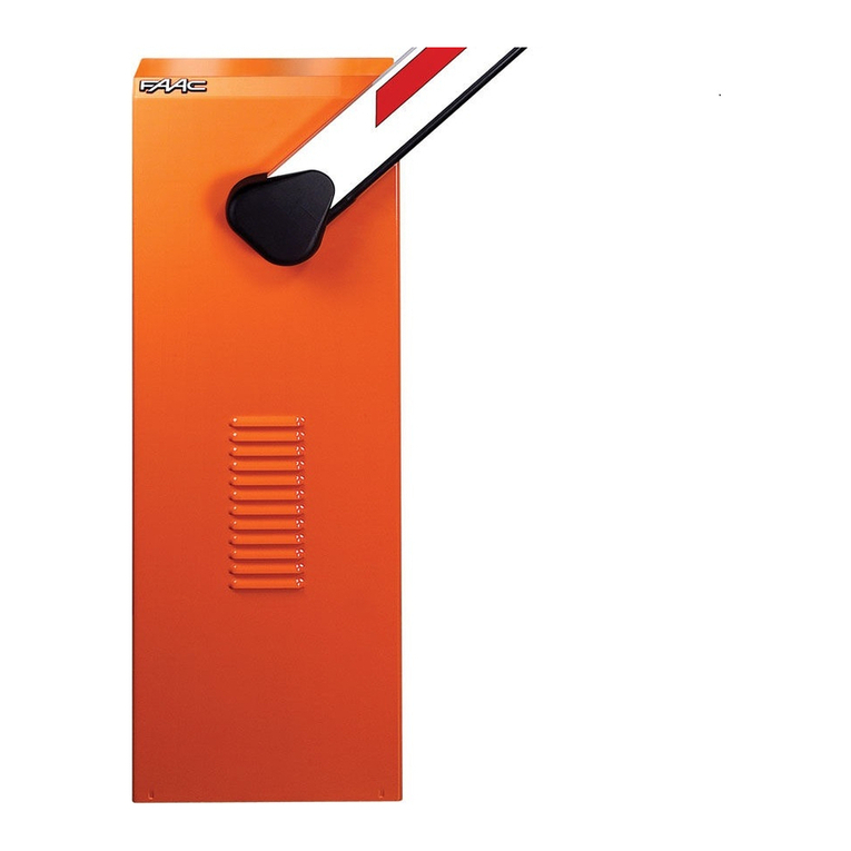
FAAC B 604 User manual

7
ENGLISH
CE DECLARATION OF CONFORMITY
Manufacturer: FAAC S.p.A.
Address: Via Benini, 1 40069 Zola Predosa Bologna ITALY
Declares that: Operator mod. B 604 24V with 230 Vac power supply
• is built to be incorporated in a machine or to be assembled with other machinery to create a machine under the provisions of
Directive 98/37/EC;
• conforms to the essential safety requirements of the other following EEC directives:conforms to the essential safety requirements of the other following EEC directives:
73/23/EEC and subsequent amendment 93/68/EEC.
89/336/EEC and subsequent amendment 92/31/EEC and 93/68/EEC
Furthermore, the manufacturer declares that the machinery must not be put into service until the machine into which it will be
incorporated or of which it will become a part has been identified and its conformity to the conditions of Directive 98/37/EC has
been declared.
Bologna, 30-06-2007
Managing Director
A. Bassi
Notes on reading the instruction
Read this installation manual to the full before you begin installing the product.
The symbol indicates notes that are important for the safety of persons and for the good condition of the automated system.
The symbol draws your attention to the notes on the characteristics and operation of the product.
INDEX
1. DESCRIPTION OF COMPONENTS page.8
2. TECHNICAL SPECIFICATIONS page.8
3. DIMENSIONS page.8
4. ELECTRIC PREPARATIONS (standard system) page.8
4. INSTALLING THE AUTOMATED SYSTEM page.9
4.1. PRELIMINARY CHECKS page.9
4.2. ON-COLUMN INSTALLATION page.9
4.3. ON-WALL INSTALLATION page.10
4.4. CLOSING DIRECTION page.11
4.5. SECURING THE ROD page.11
5. START-UP page.11
6. MANUAL OPERATION page.12
7. RESTORING NORMAL OPERATION MODE page.12
8. AVAILABLE ACCESSORIES page.12
9. MAINTENANCE page.12
10. REPAIRS page.12
10.1. REPLACEMENT OF FLASHING LAMP page.12

8
ENGLISH
B 604 AUTOMATED SYSTEM
The B 604 automated system is an electronic barrier designed for
vehicle accesses
The automated system mainly consists of three parts:
A motor body which integrates the non-reversing low voltage
motor, the control board, the flashing light, the balancing spring
and the release system.
The rod of which several types are available according to instal-
lation requirements.
The securing support, available for on-wall or on-column instal-
lation.
The built-in control unit was positioned to facilitate all the wiring,
programming and adjustment operations.
A handy manual release, protected by a personalised key, makes it
possible to move the rod manually in the event of a power cut.
Before you begin to install the barrier, read all the instructions
carefully. Incorrect installation or incorrect use of the au-
tomated system could be a source of danger to people.
The automated system was designed and built for vehicle
access only - do not use for any other purpose.
Anything not expressly specified in these instructions is not
permitted.
1. DESCRIPTION OF COMPONENTS
•
•
•
2. TECHNICAL SPECIFICATIONS
MODEL B 604
Power supply 230/115 Vac 50/60Hz
Motor power supply 24 Vdc
Absorbed power 80 W
Absorbed current 0.35 A
Max. torque. 130 Nm
Opening time 3 sec (1)
Max beam length 4 m
Max consecutive cycles 100
Operating ambient temperature
-20 ÷ +55°C
Motor body weight 20 Kg
Protection class IP 44
Dimensions See fig. 2
(1) The indicated opening time refers to a correct installation
without any slow downs
3. DIMENSIONS
4. ELECTRIC PREPARATIONS (standard system)
Fig.4 shows an installation with column support. The electrical ca-
bles to be prepared are the same as those for on-wall installation;
for the position of the cables, refer to paragraph 4.3.
To lay cables, use adequate rigid or flexible tubes.
Fig. 1Fig. 1
Pos. Description
aMotor body
bControl unit
cRelease device
dRod carrying pocket
eCovering housing
fFlashing light
gWall mounting kit (not supplied)
hColumn kit (not supplied)
Pos. Description
aMotor body
bControl unit
cRelease device
dRod carrying pocket
eCovering housing
fFlashing light
gWall mounting kit (not supplied)
hColumn kit (not supplied)
Fig. 2Fig. 2
Fig. 3Fig. 3

9
ENGLISH
Always separate connection cables of low voltage acces-
sories and control cables from power cables. Use separate
sheaths.
4. INSTALLING THE AUTOMATED SYSTEM
4.1. PRELIMINARY CHECKS
To ensure safety of users and an efficiently operating automatic
system, make sure the following conditions are observed:
When moving, the beam must not, on any account, meet any
obstacles or overhead power cables.
the characteristics of the ground (for on-column applications) or
of the wall (for on-wall applications) must guarantee stable and
safe fastening of the automated system.
make sure that an efficient earth socket for connection of the
operator is supplied.
check if the minimum manoeuvring spaces, as shown in Fig. 5,
are respected
If dimension “X”, indicated in Fig.5, is less than 500 mm, the
indicated zone MUST BE protected by a protection device
conforming to standard UNI EN 12978.
4.2. ON-COLUMN INSTALLATION
4.2.1. Walling the foundation plate
Assemble the foundation plate as shown in Fig.6.
Make a foundation plinth as shown in Fig. 7.
The dimensions of the plinth shown in the figure, refer to the
minimum dimensions enabling correct positioning of the
plate. They can vary according to the type of soil on which
the plate must be positioned.
•
•
•
•
1.
2.
Screw the four supplied tie-rods, Fig.7 ref.a, in the respective
holes, the ones with the welded nuts.
Wall the foundation plate as shown in Fig.7, supplying one or
more sheaths for routing electrical cables.
An arrow is marked on the foundation plate. This arrow must
point upward, be visible even after the plate has been wal-
led in, and must be oriented toward the release device.
Using a spirit level, check if the plate is perfectly level.
Wait for the cement to set.
4.2.2. installing the column
When the cement has set, the column and the automated system
can be installed, according to the following instructions:
Position the support tube,
(Fig. 8 ref.a), on the foun-
dation plate.
Insert the plastic housing,
(Fig.8 ref.b) and leave it to
rest on the ground.
The plastic housing can-
not be installed later.
Position the upper plate
(Fig.8 ref.c) routing the
connection cables through
the square pocket (Fig.8
ref.d) and allow them to
come out for a length of at
least 600 mm.
Tighten the 4 securing nuts.
The top plate, like the foundation plate, is marked with an
arrow. Both plates must be oriented in the same way.
4.2.3. positioning the motor body
When you have finished installing the column, position and secure
the motor body:
Unscrew the securing screws of the upper housing (Fig.9 ref.a)
and remove the housing (Fig.9 ref. b)
Unscrew the three screws (Fig.9 ref.c) securing the board cover
(Fig.9 ref. d)
Install the three supplied cable grippers in the respective holes
under the motor body (Fig.10 ref.a) respecting the orientation
shown in Fig. 10.
Insert the cables coming out of the column in the cable grippers
you have just installed, and route them out from the central
compartment for a length of about 20 cm.
Tighten the cable grippers.
1.
2.
1.
2.
1.
2.
1.
2.
1.
2.
3.
4.
5.
Fig. 4Fig. 4
Fig. 5Fig. 5
Fig. 6Fig. 6
Fig. 7Fig. 7
Fig. 8Fig. 8
Fig. 9Fig. 9 Fig. 10Fig. 10

10
ENGLISH
Position the cables inside the motor body and close the central
compartment.
Position the motor body above the column, inserting the guides
of the central support in the two rectangular pockets on the
top plate of the column.
Leave the excessive cables inside the column.
Re-open the central compartment and tighten the two screws
(Fig. 11 ref. a.
Tighten the two rear screws (Fig. 12 ref. a.
Position the lower housing (Fig. 13 ref. a) and secure it with the
four supplied screws
4.3. ON-WALL INSTALLATION
In on-wall applications, the electric cables can be embedded in
the wall, allowing them to come out of the pocket (Fig. 14 ref. a), or
they can be installed externally, using adequate tubes or sheaths.
To ascertain the position of the cables, refer to chapter 4.3.1.
4.3.1. positioning the Wall support
To correctly position the wall support bracket, follow the instruc-
tions below:
Define the position of the bracket, taking into account the
dimension of Fig. 14. We advise you to install the automated
system so that the rod is at a height of about one meter off
the ground.
Fix the motor support in the determined position, using four
expansion plugs with M10 screws, and respecting the orienta-
tion in Fig. 15.
When you carry out the fixing operations, use a spirit level to
check if the support is perfectly horizontal.
6.
7.
8.
9.
10.
11.
1.
2.
3.
4.3.2. positioning the motor body
When you have finished installing the motor support, position and
secure the motor body:
Unscrew the securing screws of the upper housing (Fig. 16 ref.
a) and remove the housing (Fig. 16 ref. b)
Unscrew the three screws (Fig. 16 ref. c) securing the board
cover (Fig. 16 ref. d)
Install the three supplied cable grippers in the respective holes
under the motor body (Fig. 17 ref. a) respecting the orientation
shown in Fig. 17.
Position the cables inside the motor body and close the central
compartment.
Position the motor body above the support, inserting the guides
of the central support in the two rectangular pockets on the
support.
Re-open the central compartment and tighten the other two
screws (Fig. 18 ref. a).
Secure the motor body with the two rear screws (Fig. 19 ref.
a).
Insert the power cables in
the cable grippers and make
them come out from the cen-
tral compartment for a length
of about 20 cm.
Tighten the cable grippers.
Install the lower housing, using
the four supplied screws, Fig.
20.
Three pre-perforated faci-
lities are available on the
lower housing for routing
any external tubes.
1.
2.
3.
4.
5.
6.
7.
8.
9.
10.
Fig. 11Fig. 11 Fig. 12Fig. 12
Fig. 13Fig. 13
Fig. 14Fig. 14 Fig. 15Fig. 15
Fig. 16Fig. 16 Fig. 17Fig. 17
Fig. 18Fig. 18 Fig. 19Fig. 19
Fig. 20Fig. 20

11
ENGLISH
4.4. CLOSING DIRECTION
The B 604 automated system is supplied designed for ri-
ghtward closing of the beam, looking at the automated
system from the release device side.
Procedure for modifying the closing direction of the beam:
Unscrew the two screw (Fig. 21 ref. a), which are on the top
part of the beam.
Remove the stop plate (Fig. 21 ref. b).
Re-position the plate you have just removed, and turn it by 180°
with respect to the original position (Fig. 22 ref. a)
Re-secure all parts with the two screws (Fig. 22 ref.b).
4.5. SECURING THE ROD
The pictures below refer to a leftward closing installation. For
a rightward closing installation, the pictures of the door
bearing rod and the release unit must be reversed.
The B 604 automated system can be coupled to three different
types of rod:
Single rod L=4 m.
Telescopic rod L=3.15 m.
Single rod L=3 m with lights or edge in rubber.
All three rods are fastened to the barrier in the same way;
just use the relevant pocket.
To secure the rod, follow the instructions below:
Assemble the rod-carrier plate (Fig.
23 ref. a) with the pocket for the
selected rod (Fig. 23 ref. b) only
using the two rear screws.
Tighten the two screws.
Fit the selected rod between the
pocket and the plate.
There is a hole at the end of the
rod. The hole must be oriented
in order to allow insertion of the
safety screw (Fig. 24 ref. a),
thus preventing the rod from
slipping down when in vertical
position.
Orient the rod correctly and fit the safety screw.
Complete securing the rod with the other two screws, Fig.25.
Position all these parts on the drive disk (Fig.26 ref. a) respecting
- for leftward closing - the orientation shown in the figure.
The rod must always be installed vertically, irrespective of
the closing direction.
1.
2.
3.
4.
•
•
•
1.
2.
3.
4.
5.
6.
Check if the rod is perfectly vertical and secure the four nuts.
5. START-UP
Wire the control unit according to your needs, following the
relevant instructions.
Connect the power cable to the
screw terminal inside the motor
body.
To connect the 230/115 Vac
power cable, respect the indi-
cations in Fig. 27
Turn the key to the OPERATION posi-
tion, see paragraph 7.
Power up the system and check
if all connected accessories are
operating correctly, addressing special attention to the safety
devices.
Perform the programming procedure following the instructions
for the control unit.
If necessary, correct the rod position, adjusting the securing nuts
of the rod-bearing plate.
When you have finished programming the control unit, and
controlled correct operation of the automated system, close
the central compartment with the three supplied screws, and
position the covering plugs as shown in Fig. 28.
Position the rear housing of the rod-bearing plate (Fig. 29 ref. a),
coupling it in the two free holes on the plate (Fig. 29 ref. b).
Re-position the top housing, Fig. 30.
Turn the key to the STOP position, see paragraph 6.
Position the housing that covers the release device, as shown in
Fig. 31, and secure it using the two supplied screws.
Turn the key back to the OPERATION position, see paragraph 7.
7.
•
•
•
•
•
•
•
•
•
•
•
•
Fig. 21Fig. 21
Fig. 23Fig. 23
Fig. 24Fig. 24
Fig. 25Fig. 25 Fig. 26Fig. 26
Fig. 28Fig. 28 Fig. 29Fig. 29
Fig. 30Fig. 30 Fig. 31Fig. 31
Fig. 27

12
ENGLISH
Position the rear plug of the release housing (Fig. 32 ref. a)
Open, on the front plug, the pre-perforated facility for the type of
installed rod, see Fig. 33 and fasten it to the release housing.
Explain, to the end-user, the correct use and operation of the
automated system.
Hand the “USER’S GUIDE” to the user and compile the enclosed
maintenance register.
6. MANUAL OPERATION
In the event of a power cut or malfunction of the automated
system, the beam can be moved manually as follows:
Insert the personalised key and take the beam to its “STOP”
position rotating it anti-clockwise until it stops, Fig. 34.
The key acts on a safety microswitch which positions the
control unit in STOP position, avoiding dangerous situations
during the release manoeuvre or during maintenance of
the automated system.
When the key is in STOP position, power to the automated
system is not cut off.
Open the release cover, Fig. 35.
Pull the release lever until it stops, (Fig. 36 ref. a)
Move the rod manually, Fig. 37.
7. RESTORING NORMAL OPERATION MODE
To prevent an involuntary pulse from putting the automated
system into operation, power down the system before re-
storing normal operation.
Lower the release lever.
Close the release cover.
Move the rod manually up to the point where manual move-
ment is no longer possible.
Take the key back to the “OPERATION” position, turning it
clockwise until it stops.
Remove the key and re-power up the system.
Following the manual manoeuvre, the first cycle could
occur without the programmed slow downs, run a couple
of cycles to check if the memory stored cycle is correctly
restored.
•
•
•
•
1.
1.
2.
3.
1.
2.
3.
4.
5.
8. AVAILABLE ACCESSORIES
The following accessories are available for the B 604 automated
system.
battery Kit
With the battery kit application, some manoeuvres can be carried
out in the event of a power cut.
The number of possible manoeuvres depends on the time
since power was cut, on the condition of the batteries, on
the number of accessories connected to the control unit,
on ambient temperature, and on the general conditions of
the automated system.
Installation procedure for the battery kit:
Cut power to the system.
Open the central compartment.
Position the batter kit on the left of the
transformer, see Fig.38.
Connect the battery kit cables to the
control unit, following the connection
lay-out shown in the control unit instruc-
tions.
Close the central compartment and restore
mains power.
balancing Kit
The length of the rods can be reduced with the balancing kit.
The table below shows the minimum lengths obtainable by using
the balancing kit:
TYPE OF ROD STANDARD L m min. L m
Telescopic rod 3.15 2.30
Fixed rod 4 2.80
Rod with lights 3 2.40
Rod with rubber edge 3 2.20
The rod lengths cannot be reduced beyond the value shown
in the table.
9. MAINTENANCE
To ensure correct long-term operation and a constant level of
safety, we advise you to generally control the system at least
every 6 months. In the “User’s Guide” booklet, there is a form for
recording jobs.
If the rod has to be removed for maintenance jobs, follow the
installation instructions in reverse order.
The rod can be removed only if it is in vertical position. Re-
moving the rod when in horizontal position could cause
dangerous situations.
10. REPAIRS
The User must not in any way attempt to repair or to take direct
action and must solely contact qualified FAAC personnel or
FAAC service centres.
10.1. REPLACEMENT OF FLASHING LAMP
Procedure for replacing the lamp of the integrated flashing light:
Make sure that the rod is in horizontal position.
Cut power to the system.
Remove the top housing, unscrewing the securing screws.
Replace the lamp (use lamp: E14 24V Max. 15W).
Re-position the top housing.
Power up the system.
1.
2.
3.
4.
1.
2.
3.
4.
5.
6.
Fig. 32Fig. 32 Fig. 33Fig. 33
Fig. 34Fig. 34 Fig. 35Fig. 35
Fig. 36Fig. 36 Fig. 37Fig. 37
Fig. 38Fig. 38
Other manuals for B 604
2
Table of contents
Other FAAC Automatic Barrier manuals
Popular Automatic Barrier manuals by other brands

CAME
CAME GARD PX Brushless installation manual

PRASTEL
PRASTEL KINFRA500 quick start guide

Roger Technology
Roger Technology ACS/BA/60 Instruction and warnings for the installer

CAME
CAME GARD series installation manual

ZKTeco
ZKTeco BG1045L-LED user manual

Tiso
Tiso Optimus 40 Installation and operation manual