Perlegear PGTVMC04 User manual

Mobile TV Cart Instruction Manual
Model: PGTVMC04
V4.0 (A)
English --------------------------------- 01-15
日本語 --------------------------------- 16-30
Thank you for choosing this Perlegear product! At Perlegear we strive to provide
you with the best quality products and services in the industry. Should you have any
issues, please don't hesitate to contact us at
Technical Support:
(US/CA)1-800-456-5231 Mon-Fri 8am - 8pm(CST)
Other Info:
[email protected](US/CA)

01
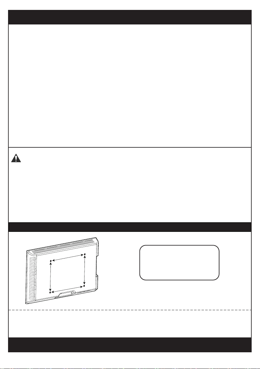
Minimum VESA pattern: 100mm/4 in (W)x100mm/4 in (H)
200 mm ≈ 7 7/8 in
400 mm ≈ 15 3/4 in
100 mm ≈ 4 in
300 mm ≈ 11 3/4 in
MAX: 400mm/16 in
MAX: 400mm/16 in
Check the VESA Pattern of Your TV before the Installation
If your TV VESA is greater than 400x400 mm/16x16 in or less than VESA
100x100 mm/4x4 in , this TV cart is NOT compatible.
If this TV cart is NOT compatible, please contact customer service at
[email protected] to find a compatible product.
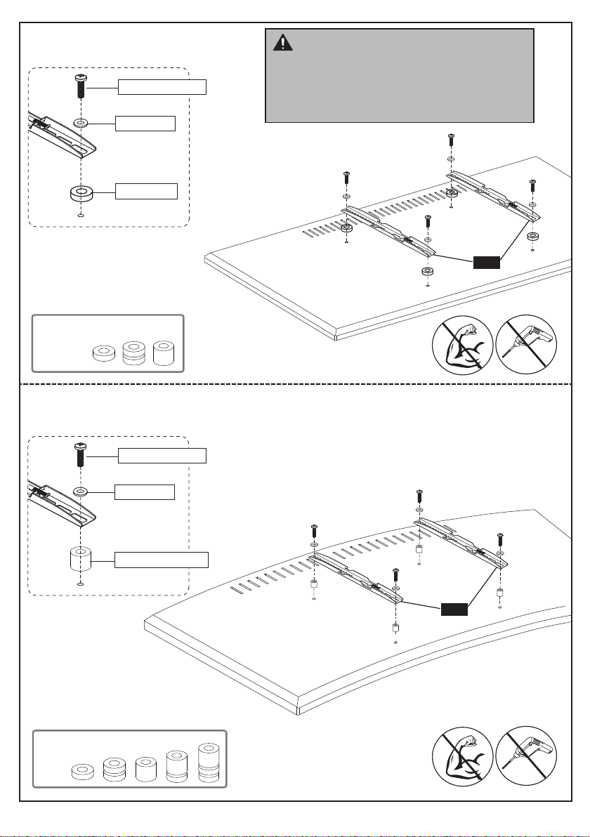
Important Safety Information
• Please read through these instructions completely before attempting
installation. If you do not understand the instructions or have any concerns
• Check package contents against Supplied Parts and Hardware List to
assure that all components were received undamaged. Do not use
damaged or defective parts. lf you require replacement parts, contact
• Not all parts and hardware included will be used.
• Do not use this product for any purpose or in any configuration not
explicitly specified in this instruction. We hereby disclaim any liability for
injury or damage arising from incorrect assembly or incorrect use of this
product.
● Serious or fatal crushing injuries can occur from tip over. To help prevent
tipping over:
● Never allow children to climb, stand, hang, or play on any part of TV or TV cart.
● Use tip over restraint or anchor to attach the TV cart to wall.
● Use of tip over restraints may only reduce, but not eliminate risk of tip over.
Tip Over Warning

02
03
07
09
06
05
04
A
B
C
02
01
15
13
08
10
14
C
D
11
E
12
C

03
(4pcs) TV2 (4pcs)
M6x15mm
Bolt
TV3 (4pcs) TV4 (4pcs)
M6x30mm
Bolt
TV5 (4pcs)
M8x50mm
Bolt
M8x25mm
Bolt
TV7 (4pcs) TV8 (4pcs)
M8 13mm
Spacer
TV9 (8pcs) TV10 (4pcs)
5mm
Spacer
20mm
Spacer
Hardware for Attaching TV Brackets to TV
A (8pcs)
M6x60mm
04 (1pc)
08 (2pcs)
14 (1pc)
06 (1pc)
H (1pc)
09 (1pc)
01 (2pcs) 02 (2pcs) 03 (4pcs)
C (12pcs)
M6x10mm
E (4pcs)D (4pcs) F (1pc) G (1pc)
15 (2pcs)
10 (1pc) 11 (2pcs)
13 (1pc)
Supplied Parts and Hardware
Supplied Parts
Hardware for Assembling the TV Cart
Phillips Screwdriver
Tools Needed (Not lncluded)
M6 M6 4mm 5mm
10mm
14mm
TV1
Tube Connector
Long Square
Tube
Short Square
Tube Caster
Lower Pole
with Holes Pole Cover
Upper pole
without holes
TV Plate TV Bracket
Shelf
Washer Nut
Bolt Small
Allen Key
Large
Allen Key Wrench
Washer
Tube Connector
Cover
05 (1pc)
Pole Connector
07 (1pc)
TV Plate Connector
& Pad
Shelf Support
Shelf Support
Connecting Plate
M4x15mm
Bolt
Bolt
B (4pcs)
M6
Socket Plate
12 (1pc)
TV6 (4pcs)
M6
Washer

04
Step 1
Step 2
x2 x2
x4 x1
Long Square
Tube
Short Square
Tube
01 02
03
M6x60mm
Bolt
M6
Socket Plate
Secure Casters [03] to the square tubes [01]
and [02] by using the provided wrench [H]
Turn this nut to adjust the height of caster [03]
Step1-1
Step1-2
Secure the Casters to the Square Tubes
Casters Wrench
x1 x8
x4 x1
04
04
Secure the square
tubes [01] and [02] to
the tube connector
[04] using bolts [A] and
socket plate [B]
A
G
Front
BACK
Tube Connector
Secure the Casters to the Square Tubes
H
01
02
03
03
35/64 in (14mm)
Wrench
13/64 in (5mm)
Large Allen Key
B
A
13/64 in (5mm)
Large Allen Key
B
01
02
G

05
Step 3 Secure the Poles [06] and [09] to the Base
x1
05
x1
x1
07
x2
Lower Pole
with Holes
Upper Pole
without Holes
x1
09
Pole Connector
C
1. Attach tube connector cover [05] to the tube connector [04].
2. Secure the lower pole [06] to the tube connector [04] using bolts [C].
3. Insert the pole cover [08] into the top of the pole [09].
4. Thread the pole connector [07] to the top of the lower pole [06]. Thread the
pole [09] to the pole connector [07].
x2
M6x10mm
Bolt
Tube Connector
Cover
x1
5/32 in (4mm)
Small Allen Key
F
08
06
Pole Cover
C
07
06
09
08
09
06
05
04
5/32 in (4mm)
Small Allen Key
Warm Tips:
It is recommended to wear a pair of gloves
to avoid hurting you hands while assembling.
F

06
Step 4 Secure Square Plate to Upper Pole [09]
x1 x1
x4 x1
TV Plate
13 14
D
4.1
C
D
4.2 Secure the TV plate [14] to TV plate connector [13] using bolts [C] and washers [D].
Slide the TV plate connector and pad
[13] over the top of the pole [09] and
secure the connector using Small Allen
Key [F].
TV Plate Connector
& Pad
M6
Washer
13
13
14
09
09
5/32 in (4mm)
Small Allen Key
5/32 in (4mm)
Small Allen Key
5/32 in (4mm)
Small Allen Key
F
x4
M6x10mm
Bolt
C
Note:Please make sure you have tightened
the bolt before hanging your TV/monitor.
F

07
Step 5
Secure the Brackets to the TV
Note: The bolts are shown in accordance with the actual size
M6 TV2 x4
M6 x 15mm
TV3 x4
M6 x 30mm
M4 TV1 x4
M4 x 15mm
M8
TV4x4
M8 x 25mm
TV5 x4
M8 x 50mm
X2
TV Bracket
15
Note: The washer and spacers are shown in accordance with the actual size
TV6x4
M6 Washer
TV7 x4
M8 Washer
TV Bolts

08
Only one bolt size fits your TV.
M6M4 M8
Bolt length:Verify adequate thread engagement with bolts or bolts/spacers combination.
We recommend thread engagement by at least 5 turns.
-Too short will not hold the TV.
-Too long will damage the TV.
Too Short Too Long Correct Correct
Select TV Bolts
CAUTION: Ensure the TV brackets
15 are EQUALLY CENTERED on your
TV and securely fastened in place.
15
UP
TV9 x8
5mm Spacer
TV10 x4
20mm Spacer
TV8 x4
Spacers
[if needed]
13mm Spacer

09
Option B (For Round Back TV)
Option A (For Flat Back TV)
(If needed)
TV1/TV2/TV4
TV8/TV9
TV6/TV7
15
15
10
TV1/TV3/TV5
TV8/TV9/TV10
TV6/TV7
10
Please note: The bolt hole locations
on your TV may vary in accordance of
the manufacturers design of the TV. We
are only illustrating possible locations
of the bolt holes.
Alternate Spacer Setups

Spacers may be necessary for 2 holes ONLY.
Option C (For TV with A “Bump”)
Option D
For cable interference or inset holes, use spacers TV7, TV8 and TV10 to create extra
space between the TV and TV brackets
(If needed)
TV1/TV2/TV4
TV6/TV7
TV8/TV9/TV10
TV1/TV3/TV5
TV1/TV3/TV5
TV6/TV7
TV6/TV7
10
15
15
(If needed)
TV8/TV9/TV10
10
(If needed)
TV8/TV9
Alternate Spacer Setups

11
Step 6 Hang TV to TV Plate [14]
6-1 Hang the TV with brackets to the TV plate
6-2 Push the bottom of the TV to TV plate
6-2
6-1
HEAVY! You may need
assistance with this step.

12
Step 7 Secure TV to TV Plate [14]
Tighten the safety bolt on the bottom of the TV brackets to secure TV to the
TV plate.
Safety bolt
(Not Included)
Note: If the TV cart is unstable on a
flat ground, you can adjust the
pre-assembled nut on the caster until
the TV cart is stable.
Unlock Lock
14

13
x2
x6
x1
C
11 13/16 in
(300mm)
E
C
Secure shelf supports [11] to the shelf [10]
using nuts [E]
8.1
8.3
8.2
Secure shelf [10] to the shelf support connecting
plate [12] using bolts [C]
10 12
10
11
12
06
5/32 in (4mm)
Small Allen Key
5/32 in (4mm)
Small Allen Key
Step 8 Secure the Shelf [10] to Pole [06]
E
x1
x1
10
12
x4
11
M6x10mm
Bolt
Shelf Shelf Support
M6 Nut
x1
Shelf Support
Connecting Plate
C
5/32 in (4mm)
Small Allen Key
F
Wrench
H
3/8 in (10mm)
Wrench
Secure shelf support connecting plate
[12] on the pole [06] using bolts [C]
according to your height need.
F
F

14
Step 9 Cables Management
Option A
Option B

15
Option C

テレビスタンド取扱説明書
モデル: PGTVMC04
この度、当社の製品をお買い上げ頂きまして誠にありがとうございます。お客様にご満
足いただける製品·サービスをご提供できるように日々努力し、商品の開発·改良、サ
ービスの向上などに力を注いでいます。また、この商品について、何かご問題、ご不明
な点がございましたら、ぜひ、ご遠慮なく下記までご連絡ください。24時間以内にお返
事を差し上げております。
メール: [email protected]

16
最小VESA規格: 100mmx100mm
最大:400mm
最大
:400mm
取り付ける前にテレビのVESA規格を確認
ご注意:お持ちのテレビVESA規格は100mmx100mm未満、400mmx400mmを超え
る場合は、当商品はお持ちのテレビに対応していません。
当商品はお持ちのテレビスタンドに不適合な場合は、アフターサービスに連絡して、
適合のテレビ壁かけ金具をおすすめです。連絡先:[email protected]
安全上のご注意:
• 組み立てる前に必ずこのマニュアルをよくお読みになり、正しくお使いください。取り付けや
取扱説明書に何かご不明な点がございましたら、販売者や専門知識のある業者の方にご依頼く
ださい。連絡先:[email protected]
• 組み立てる前に、すべての部品が揃っており、破損してないことを確認してください。
足りない部品又は破損している部品のある場合は、当社に連絡してください。
お問い合わせ先:[email protected]
• すべての部品を使用するわけではありません。
• 設置の際は取扱説明書で記載される以外の使用目的で使用しないでください。取り付け不備や
取り扱い不備による事故や損傷については、当社では一切の責任を負いません。
● 本製品に乗る、脚をかける、ぶら下がる、棚の上に乗る等の行為をすると転倒し怪我の原因
となることがあります。転倒防止のために下記のように注意してください。
● 製品の上に脚を掛けたり、腰を掛けたり、もたれたりしないでください。また、小さなお
子様がゆすったりして遊ばないように注意してください。
● 転倒ストッパーまたは、テレビと壁や柱などをつないで、転倒防止の処置を行ってくださ
い。
転倒防止の処置はテレビスタンドの転倒を減少するかもしれませんが、必ず転倒の障害を除く
訳ではありません。
転倒警告

17
03
07
09
06
05
04
A
B
C
02
01
15
13
08
10
14
C
D
11
E
12
C

18
(4本)TV2 (4本)
M6x15mm
ボルト
TV3 (4本) TV4 (4本)
M6x30mm
ボルト
TV5 (4本)
M8x50mm
ボルト
M8x25mm
ボルト
TV7 (4本) TV8 (4本)
M8 M6x13mm
スペーサー
TV9 (8本) TV10 (4本)
M8.5x5mm
スペーサー
M8.5x20mm
スペーサー
テレビにTVブラケットを取り付ける部品
A (8本)
M6x60mm
04 (1個)
08 (2個)
14 (1本)
06 (1本)
H (1本)
09 (1本)
01 (2本)02 (2本)03 (4個)
C (12本)
M6x10mm
E (4本)D (4本)F (1本)G (1本)
15 (2本)
10 (1個)11 (2本)
13 (1セット)
部品一覧
組み立て部品
テレビテレビカートをを取り付けるハードウェア類
ドライバー
必要な工具類(別売)
M6 M6 4mm 5mm
10mm
14mm
TV1
チューブコネクタ長方形チューブ 短方形チューブ キャスター
穴付き下部
ポール ポールカバー 穴なし上部ポール
方形プレート TV ブラケット
シェルフ
ワッシャー ナット
ボルト 小六角レンチ 大六角レンチ
レンチ
ワッシャー
チューブコネクタ
カバー
05 (1個)
ポールコネクタ
07 (1個)
方形プレートコネク
タ&ゴムパッド
シェルフサポート
シェルフサポートコ
ネクタプレート
M4x15mm
ボルト
ボルト
B (4本)
M6
ソケットプ
レート
12 (1個)
TV6 (4本)
M6
ワッシャー
Table of contents
Other Perlegear TV Mount manuals