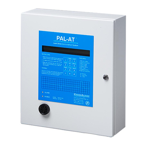
Permalert LiquidWatch Series User manual


Notice
The information contained in this manual, including but not limited to any product specifications, is subject to
change without notice.
PERMALERT ESP (PERMALERT) PROVIDES NO WARRANTY WITH REGARD TO THIS MANUAL OR ANY
OTHER INFORMATION CONTAINED HEREIN AND HEREBY EXPRESSLY DISCLAIMS ANY IMPLIED
WARRANTIES OF MERCHANTABILITY OR FITNESS FOR ANY PARTICULAR PURPOSE WITH REGARD TO
ANY OF THE FOREGOING. PERMALERT ASSUMES NO LIABILITY FOR ANY DAMAGES INCURRED
DIRECTLY OR INDIRECTLY FROM ANY TECHNICAL OR TYPOGRAPHICAL ERRORS OR OMISSIONS
CONTAINED HEREIN OR FOR DISCREPANCIES BETWEEN THE PRODUCT AND THE MANUAL. IN NO
EVENT SHALL PERMALERT BE LIABLE FOR ANY INCIDENTAL, CONSEQUENTIAL, SPECIAL, OR
EXEMPLARY DAMAGES, WHETHER BASED ON TORT, CONTACT OR OTHERWISE, ARISING OUT OF OR
IN CONNECTION WITH THIS MANUAL OR ANY OTHER INFORMATION CONTAINED HEREIN OR THE USE
THEREOF.
Caution --This manual may not be up-to-date.
Please check the PermAlert website, www.permalert.com, for the latest revision of this manual.
The manual is typically revised at least once a year. The revision date is on the back cover.

LiquidWatch Installation Manual
1
Table of Contents
1Introduction...............................................................................................3
1.1 General Description......................................................................................................... 3
1.2 Applications ..................................................................................................................... 3
1.3 Receiving and Handling Precautions............................................................................... 3
1.4 Material and Equipment Normally Supplied by PermAlert ............................................... 3
1.5 Material and Equipment Normally Supplied by Contractor............................................... 4
2LiquidWatch Installation...........................................................................5
2.1 Alarm Panel Installation................................................................................................... 5
2.2 Internal Wiring.................................................................................................................. 7
2.3 Control Relays ................................................................................................................. 7
2.4 RS-232 Port..................................................................................................................... 7
2.5 Intrinsically Safe - UL/CUL............................................................................................... 8
2.6 FCC ................................................................................................................................. 8
3Probe Installation......................................................................................9
3.1 UL/CUL LiquidWatch Requirements................................................................................ 9
3.2 Probe Configuration......................................................................................................... 9
3.3 Probe Installation........................................................................................................... 11
3.4 Surge Suppressor.......................................................................................................... 13
3.5 Typical Installations........................................................................................................ 14
3.6 PHLR Hydrocarbon Probe............................................................................................. 19
3.6.1 Cleaning Sensor Elements Procedure ................................................................ 19
3.6.2 Testing the PHLR................................................................................................ 20
3.6.3 Troubleshooting .................................................................................................. 20
3.7 Probe Tests ................................................................................................................... 21
3.7.1 PHL-LW - Tests................................................................................................... 21
3.7.2 PHL-LW - Reset.................................................................................................. 21
4Output Relay Module Installation........................................................... 23
4.1 Output Relay Module Wiring.......................................................................................... 23

LiquidWatch Installation Manual
2
5LiquidWatch Operation........................................................................... 25
5.1 General.......................................................................................................................... 25
5.1.1 Theory of Operation ............................................................................................ 25
5.1.2 Power Up............................................................................................................. 25
5.1.3 Initial Display.......................................................................................................25
5.1.4 Contrast Adjustment............................................................................................ 25
5.1.5 Clock Battery....................................................................................................... 25
5.1.6 Installation Instructions........................................................................................ 26
5.2 Operating LiquidWatch...................................................................................................26
5.3 Setup.............................................................................................................................. 26
5.4 Probe On/Off.................................................................................................................. 28
5.5 History............................................................................................................................ 28
5.6 Display Setup................................................................................................................. 29
5.7 Configuration.................................................................................................................. 29
5.7.1 Test Mode ...........................................................................................................30
5.7.2 Time and Date.....................................................................................................30
5.7.3 Number of Probes............................................................................................... 31
5.7.4 Number of Relays................................................................................................ 31
5.7.5 System I.D...........................................................................................................31
5.7.6 Baud Rate ........................................................................................................... 31
5.7.7 Phone Number....................................................................................................32
5.7.8 Version................................................................................................................ 32
6Monitoring ............................................................................................... 33
6.1 Monitor........................................................................................................................... 33
6.2 Normal Messages Displayed ......................................................................................... 33
6.3 Fault Messages Displayed............................................................................................. 33
6.4 Alarm Silence Feature.................................................................................................... 34
6.5 Output Relays ................................................................................................................ 34
Appendix......................................................................................................... 35
System Testing....................................................................................................................... 35
Communications Options........................................................................................................ 36
Troubleshooting...................................................................................................................... 37
Warranty ......................................................................................................... 39

LiquidWatch Installation Manual
3
1 Introduction
1.1 General Description
This LiquidWatch®Installation and Operation Manual is intended for use as a general guide for
LiquidWatch Leak Detection Systems. Users (installers) should independently evaluate the suitability of
this information and PermAlert’s products for their application and specific installation. If you received a
PermAlert product that is not described in this manual, contact PermAlert for the appropriate instructions.
1.2 Applications
The LiquidWatch system consists of an electronic microprocessor-based alarm panel that monitors
probes. The probes may be installed in many applications including: secondary contained piping, double
wall tanks, sumps, computer room subfloors, cleanroom subfloors or any area where liquids need to be
detected. There are two LiquidWatch models available:
Model LW64 monitors up to 64 probes in ordinary locations.
Model LW64-IS monitors up to 64 probes in Class I, Division 1, Groups C & D, hazardous
locations.
Each base system will monitor up to 8 probes and has a common alarm output relay. If additional
probes or output relays are required, the following modules are available:
Model RPM-8 is a remote probe module that can monitor up to 8 probes.
Model ORM-4 is an output relay module with 4, 10 A, 250 VAC rated relays.
Model ORP-16 is an output relay panel with 4, 10 A, 250 VAC rated relays, expandable to 16
relays.
1.3 Receiving and Handling Precautions
The following general precautions should be observed:
1. Read this manual carefully before beginning any work. Do not use substitute materials or short
cut recommended procedures. Understanding and following this guide is essential to avoid
installation problems.
2. Collect the needed quantities of all materials well in advance of scheduled work.
3. Check the packing list against received items. Report immediately any shortages or damaged
materials to the delivering carrier.
4. All probes must be tested immediately upon receipt following the probe test procedures contained in
this manual. Report immediately to PermAlert any probes that fail this quality control test.
5. System drawings, provided by the designer, should indicate the extent, general location and
arrangement of leak detection equipment and probes. The contractor (installer) should become
familiar with all details of the installation before proceeding.
6. A qualified electrician should perform electrical work.
1.4 Material and Equipment Normally Supplied by PermAlert
Each system may include the following items as quoted:
1. Leak detection alarm panel
2. Communication cable
3. Lead wire
4. Probe adapter assembly
5. Probes

1 Introduction
4
6. Watertight junction boxes conforming to NEMA 4X
Maximum No. of
Cable Junctions
in Enclosure
Enclosure
Dimensions
4
6” x 6” x 4”
6
8” x 6” x 4”
8
10” x 8” x 4”
7. Watertight cord grips
8. Shrink tubing for cable connectors
9. RTV adhesive/sealant for cable connectors
1.5 Material and Equipment Normally Supplied by Contractor
Each system may require the installing contractor to supply the following items:
1. Electrical conduit, junction boxes and wiring, as required.
2. Ohmmeter for testing.
3. Hot air gun for shrink tube application on connector assemblies.
NOTE:
All probe lead and communication cable should be run in conduit to protect the cable from physical
damage. In an area subject to strong electrical interference, grounded metal conduit is recommended.
Contact PermAlert for additional information.

LiquidWatch Installation Manual
5
2 LiquidWatch Installation
2.1 Alarm Panel Installation
1. The standard LiquidWatch alarm panel may be permanently mounted indoors or outdoors in an area
with an ambient temperature of not less that 0°F and not exceeding 120°F. The enclosure must not
be located in direct sunlight, to prevent excessive heat buildup.
2. The power conduit entrance should be located in the upper right corner of the enclosure (see Figures
1 and 2). Model LW64-IS must not have the power conduit in the lower portion of the
enclosure, where it will interfere with the partition or the intrinsically safe wiring
compartment. Inspect and clean the interior of the enclosure before continuing. Connect all
electrical conduits.
3. Wire the unit to an isolated (circuit breaker protected) 120 VAC, 50/60 Hz circuit. Earth ground
must be connected solidly to the ground screw, which is located in the upper right corner of the
LiquidWatch alarm panel back plate. Failure to connect earth ground can result in faulty alarm
panel operation. See Figures 1 and 2 for LiquidWatch alarm units wiring diagrams.
4. The LiquidWatch alarm panel is supplied with an internal probe board that can monitor up to 8
probes. An optional remote probe module, RPM-8, can monitor 8 probes. A total of 7 RPM-8 boards
can be monitored for a total system capacity of 64 probes. Each remote probe module is connected
in parallel to the internal probe board using a 15 conductor shielded cable.
5. Each probe is supplied with 20 feet of shielded probe lead cable and an integral probe adapter.
Additional probe lead cable is required if the probes are not located close enough to the alarm panel
or remote probe modules. It is recommended to run all lead cable in conduit for protection of the
cable.
6. The LW64-IS system has a partition covering the internal probe board. Remove the partition (cover)
over the probe board on the LiquidWatch panel by removing the 5 mounting screws.
7. Install the lead cables using the instructions in this manual. The cable must exit the enclosure under
the partition for LiquidWatch Model LW64-IS (see Figures 2 and 3).

2 LiquidWatch Installation
6
Figure 1
Component Layout for LiquidWatch Model LW64
Figure 2
Component Layout for LiquidWatch Model LW64-IS

LiquidWatch Installation Manual
7
Figure 3
Enclosure Dimensions
2.2 Internal Wiring
LiquidWatch is shipped with a 2 line x 20 characters LCD, a green LED (power), a red LED (alarm), and
a horn on the door of the panel. The wiring for the horn is a 2-wire cable connected to a connector on
the back of the LCD. The keypad is a 4 key membrane switch. The green LED is illuminated when the
panel is powered. The red LED is illuminated when any probe is in alarm.
There are ground wires that must be securely connected to the white backplate mounting screws.
In each case, the external tooth lock washer should be placed against the white painted
backplate and then the ring terminal placed on top of the lock washer (see Figures 1 and 2 for
Ver. B LiquidWatch Controller Board):
LiquidWatch model LW64-IS has 2 ground wires from the intrinsically safe barrier that are
factory-installed to the 2 mounting screws beneath the intrinsically safe partition. If the backplate
is removed and reinstalled, reconnect the ground wires.
The shield wires from all shielded probe leads and communication cables must be connected to
either of the mounting screws at the bottom of the backplate as shown. The shield wires should
be connected together in a ring terminal(s) (#10 stud).
2.3 Control Relays
When LiquidWatch detects a fault condition, it switches a SPDT common alarm output relay rated for
250 VAC, 10 A. This relay is located on the main controller board. LiquidWatch is shipped with the
relays configured to operate in a normally energized mode, so they de-energize in the alarm state
and are not reset until the alarm condition is cleared.
When LiquidWatch is in alarm, the silence key can be pressed to silence the horn. If an optional output
relay module(s) is installed, 4 relays per module are available. The relay(s) remains switched until the
fault is cleared or the active probe is taken off-line.
2.4 RS-232 Port
LiquidWatch is provided with an RS-232 communications port. Refer to Figures 1 or 2 for the location.
There is a 9-pin connector located on the controller board.

2 LiquidWatch Installation
8
2.5 Intrinsically Safe - UL/CUL
LiquidWatch LW64-IS is Listed by Underwriters Laboratories, Inc., for use in ordinary locations. LW64-IS
provides intrinsically safe output circuits for use in Class 1, Division 1, Groups C and D hazardous
locations when used with LiquidWatch sensor probes and installed in accordance with the instructions in
this manual. Refer to Section 3.1 for specific probe UL requirements. Also, refer to LiquidWatch control
drawing, Figure 4, for intrinsic safety requirements.
THE MAXIMUM OPERATING VOLTAGE ALLOWED IN THE LIQUIDWATCH PANEL IS 250 VAC. IN
ADDITION, THE VOLTAGE ON ANY WIRES TO THE CONTROL RELAYS MUST BE LIMITED TO 250
VAC.
The partition (cage) must be installed over the intrinsically safe barrier and internal probe board before
operating the system.
Figure 4
LiquidWatch Control Drawing
2.6 FCC
The user is cautioned that any changes or modifications, not expressly approved by the party
responsible for FCC compliance, could void the user’s authority to operate the equipment.
NOTE: This equipment has been tested and found to comply with the limits for a Class A digital device,
pursuant to Part 15 of the FCC Rules. These limits are designed to provide reasonable protection
against harmful interference when the equipment is operated in a commercial environment. This
equipment generates, uses and can radiate radio frequency energy and if not installed and used in
accordance with this instruction manual, may cause harmful interference to radio communications.
Operation of this equipment in a residential area is likely to cause harmful interference in which case the
user will be required to correct the interference at his own expense.

LiquidWatch Installation Manual
9
3 Probe Installation
3.1 UL/CUL LiquidWatch Requirements
The LiquidWatch model LW64-IS is listed by Underwriters Laboratories, Inc. and provides intrinsically
safe output circuits for use in Class 1, Division 1, Groups C and D hazardous locations when used with
probes listed below and installed in accordance with the instruction in this manual.
The probe configurations are:
1. PHL-LW solid-state hydrocarbon sensor and PWS-LW solid-state water or conductive liquid sensor.
2. All PermAlert supplied probes and float switches with an integral LW-PA probe adapter, which
operate as a simple dry contact switch closure.
3. A PermAlert LW-PA probe adapter connected to a customer supplied switch, if the switch operates
as a simple dry contact closure with no external power supplied to the switch. The switch may
operate as normally open or normally closed.
3.2 Probe Configuration
The LiquidWatch alarm panels are designed to monitor up to 64 probes. The 64 probes are organized in
8 banks of 8 probes. The standard alarm unit has probe bank 1 installed within the enclosure (see
Figures 1 and 2). This can monitor probes 1 –8, connected to terminal strip P1. If additional probes are
monitored, remote probe modules (Model RPM-8) are required. Each RPM-8 has a bank select jumper,
P3 that can be set to bank 2 through bank 8 and will monitor 8 probes as follows (see Figure 5):
Bank Probe Numbers
2 9 - 16
3 17 - 24
4 25 - 32
5 33 - 40
6 41 - 48
7 49 - 56
8 57 - 64
Labels are supplied to place on the circuit board next to the terminal strip P1 to renumber the probe
terminals.
The RPM-8’s are connected with a 15 conductor shielded communication cable. The standard
communication cable supplied by PermAlert has the following color code and is connected to terminal
strip P2, numbered 1 - 16 as follows:
Terminal Pin # Color Function
1 Black Probe #1
2 Not Used Bank #1 Select
3 White Probe #2
4 Red Bank #2 Select
5 Green Probe #3
6 Orange Bank #3 Select
7 Blue Probe #4
8 White/Black Bank #4 Select
9 Red/Black Probe #5
10 Green/Black Bank #5 Select
11 Orange/Black Probe #6
12 Blue/Black Bank #6 Select
13 Black/White Probe #7
14 Red/White Bank #7 Select
15 Green/White Probe #8
16 Blue/White Bank #8 Select

3 Probe Installation
10
Figure 5
Remote Probe Module
The communication cable runs from P2 on probe bank 1 card in the main enclosure to P2 on the first
RPM-8, then to P2 on the next RPM-8, etc. Normally each RPM-8 is set to a unique probe bank select
number. The maximum distance from a probe to the main alarm panel (including communication cable)
is 20,000 feet using probe wire and communication cable. Figure 6 is a typical field-wiring layout.
The communication cable can branch from one RPM-8 to 2 or 3 RPM-8’s in a star pattern. This may be
convenient if the probes are located in separate areas of a site. The maximum number of
communication cables that can be connected together at terminal strip P2 is 4.
When 2 or more wires are going into the same terminal, it is recommended that a wire crimp ferrule be
used to crimp the wires together. Then a single ferrule is inserted into each terminal pin. This will make
installation easier and reduce field-wiring errors. The following is a guide for crimping 2, 3, or 4 wires
together.
Number of wires Ferrule size (AWG) Crimp tool setting (mm)
2 16* or 14 1.0* or 1.5
3 14 1.5
4 14 1.5
* A #16 AWG ferrule is the largest size allowed connected to P2 on probe bank 1 on Model LW64-IS.
PermAlert recommends using Eclipse Model 300-016 Wire Ferrule Crimp Tool or equivalent, available
from PermAlert.

LiquidWatch Installation Manual
11
Figure 6
LiquidWatch Field Wiring Diagram
3.3 Probe Installation
1. Each PermAlert supplied probe is furnished with an integral probe adapter. Probe adapters are also
available to connect customer supplied probes to the LiquidWatch monitoring system. A standard 6”
x 6” x 4” junction box can house several probe adapters or several standard probe splices (see
Figures 7 and 8). (PermAlert can supply NEMA 4X junction boxes and cord grips.)
2. Mount a junction box or a remote probe module at a location close to the point being monitored.
PermAlert supplies probes with 20 feet of probe lead cable, but additional lead cable may be used if
necessary.
3. Figures 10 through 13 show typical probe installations. Install the probe and use electrical conduit
and/or watertight cord grips, as necessary, to prevent water entry where the probe lead penetrates
the monitored area. Cord grip part # 8057955 is for the probe lead cable.
4. Once the probe is installed, the probe lead should be routed to the junction box or the remote probe
module. Trim the excess length of the probe lead before splicing it. Splice the leads by using the
crimp connectors supplied with the probe or probe adapter. Make sure the shrink tubing on the
connector covers the insulation of the wires, so no bare copper wire is exposed. Heat the splice with
a heat gun to seal the adhesive-lined shrink tubing on the connector (see Figures 7 and 8).
5. The shields from each communication cable and all probe cables in a junction box must be
connected together at each RPM-8. The shields must be grounded in the alarm panel to one
of the 4 mounting screws for the backplate (see Section 2.2).

3 Probe Installation
12
Figure 7
Probe Adapter Installation
Figure 8
Probe Installation

LiquidWatch Installation Manual
13
3.4 Surge Suppressor
An optional Surge Suppressor (Model LWSA, part no. 8027572) is available for installations where
lightning strikes are prevalent in the vicinity of the LiquidWatch probes or probe wiring. The LWSA
includes a 10” x 8” NEMA 4X enclosure. The suppressor reduces the possibility of an induced voltage in
the cable, caused by a lightning strike, damaging the LiquidWatch panel.
Typically the enclosure is located close to the LiquidWatch Alarm Panel and is connected to it by an 18-
conductor cable (only 16 conductors are needed). The cable is installed from terminal strip P2 on the
Probe Bank 1 card in the main panel to terminal strip P3 in the LWSA. Probes 1-8 are connected to
terminal strip P1 in the LWSA instead of the original Probe Bank 1 card. A 15-conductor
communications cable is connected to terminal strip P2 if additional RPM-8s are installed.
The 12” green ground wire is soldered to the LWSA PCB and must be securely connected to earth
ground. The shield wires from all shielded probe leads and communication cables in the enclosure must
be connected to the earth ground connection.
Figure 9
Optional Surge Suppressor

3 Probe Installation
14
3.5 Typical Installations
Figures 10 through 14 show typical installations.
Contained Pipe Pressurized Contained Pipe
Double-Wall Tanks
Contained Area
Figure 10
Typical PHLR-LW and PHLR-P-LW Probe Installations

LiquidWatch Installation Manual
15
Figure 11
Typical PHL-LW and/or PWS-LW Probe Installation

3 Probe Installation
16
Figure 12
Typical PSTV-LW Tank Float Switch Installation

LiquidWatch Installation Manual
17
Figure 13
Typical PTHL-LW Float Switch Installation

3 Probe Installation
18
Figure 14
Typical PFS-LW Installation
This manual suits for next models
5
Table of contents
Other Permalert Measuring Instrument manuals
Popular Measuring Instrument manuals by other brands

CaddyTalk
CaddyTalk CUBE manual

Fema
Fema M60-C1 user manual

PP Systems
PP Systems WMA-5 Operation manual

Design Technology
Design Technology Tiny-Tach 2A operating instructions

Alpes Lasers
Alpes Lasers Cascade Laser Starter Kit instruction manual

Mobiletron
Mobiletron TX011 Installation and operating instructions

Shaw
Shaw Superdew 3 operating instructions

Seitron
Seitron BE COOL V1 SMART quick guide

Cincinnati
Cincinnati CL-900 Series Operation, safety and maintenance manual

Fisher Scientific
Fisher Scientific accumet AP 110 accumet AP 115accumet AP 125 instruction manual

Sylvac
Sylvac EVO Bluetooth quick start guide

jacarta
jacarta iMeter Master user manual