Perrot WT User manual

TDP058e.doc Rev. 29.09.2010 (v1.16) Page 1 / 33
Perrot REGNERBAU CALW GmbH Industriestraße 19-27 / D-75382 Althengstett / Germany
Phone: 0049-7051-162-0 / Fax : 0049-7051-162–133
E-mail: perrot@perrot.de / E-mail Konstruktion : technik@perrot.de
Operating Instructions
Wireless Transmitter
for Greenkeeper Win
PERROT
ZW01 99557

TDP058e.doc Rev. 29.09.2010 (v1.16) Page 2 / 33
Perrot REGNERBAU CALW GmbH Industriestraße 19-27 / D-75382 Althengstett / Germany
Phone: 0049-7051-162-0 / Fax : 0049-7051-162–133
E-mail: perrot@perrot.de / E-mail Konstruktion : technik@perrot.de
Contents
1SAFETY......................................................................................................................................................... 4
1.1 SYMBOLS OF HINTS GIVEN IN THESE OPERATING INSTRUCTIONS .............................................................. 4
1.2 DANGERS IF THE SAFETY INSTRUCTIONS ARE NOT OBSERVED.................................................................. 4
2DESCRIPTION............................................................................................................................................. 5
2.1 CONTROL SYSTEM COMPONENTS ............................................................................................................. 5
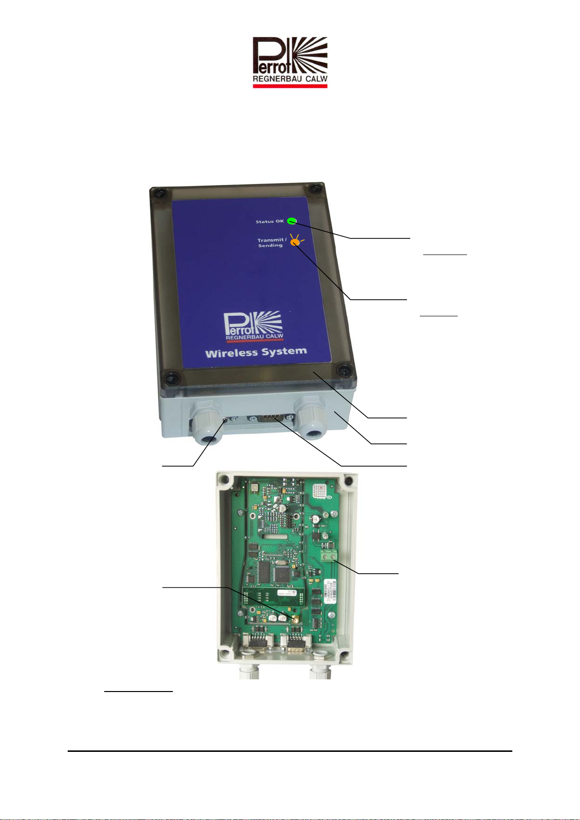
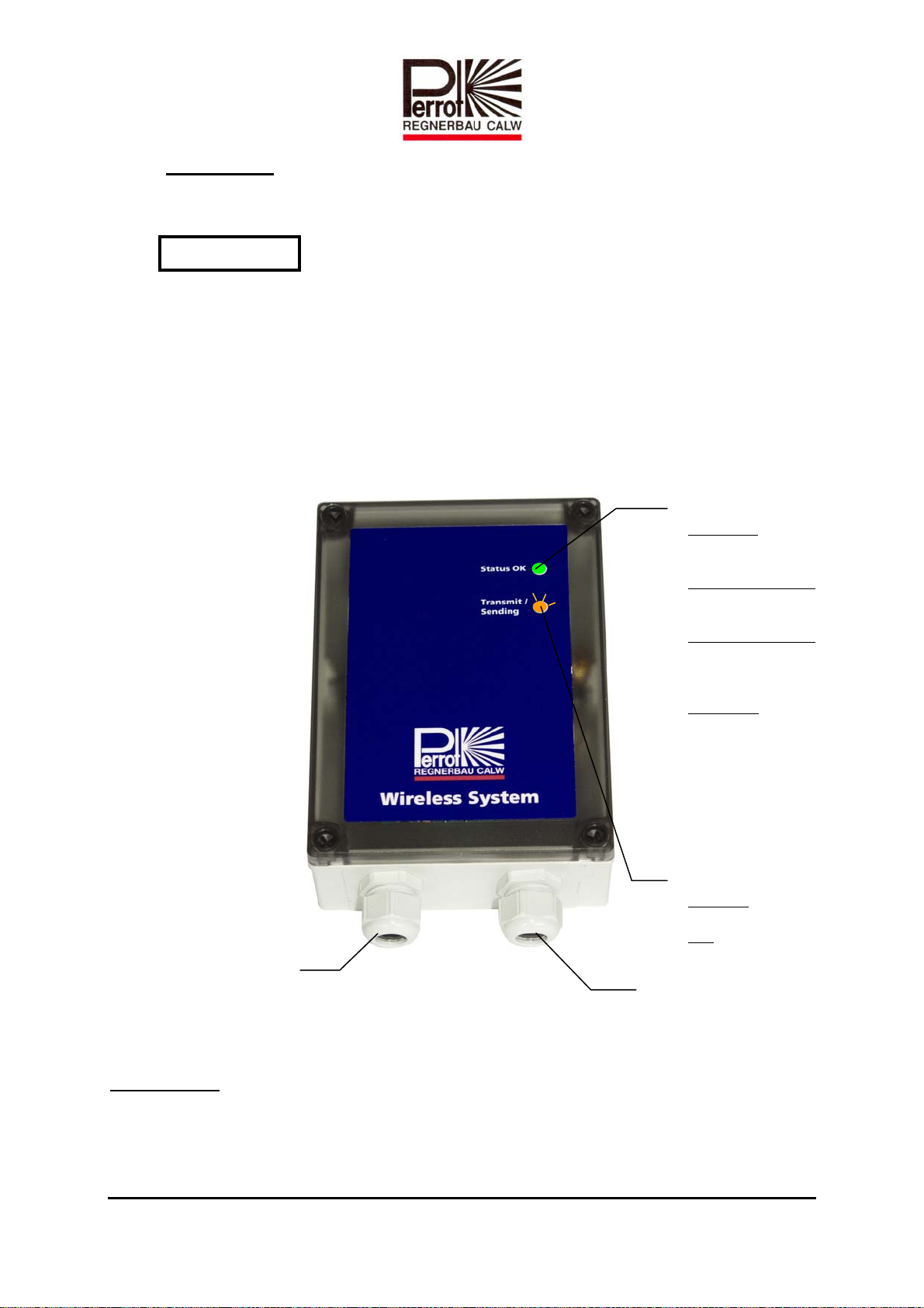
2.1.1 Wireless Base Unit WBU (ZK28 93 684)........................................................................................ 5
2.1.2 Wireless Transmitter WT (ZK28 93682) ......................................................................................... 6
2.1.3 Wireless Repeater Unit WRU (ZK28 93 683).................................................................................. 7
2.2 POWER SUPPLY ACCESSORIES .................................................................................................................. 8
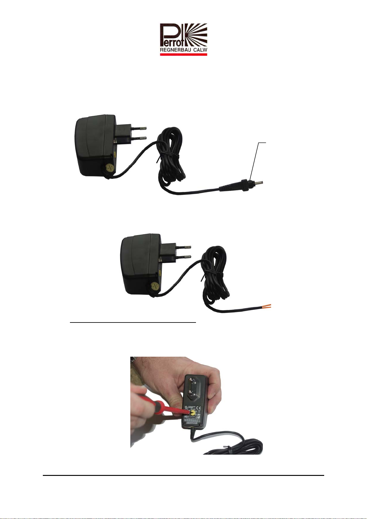
2.2.1 Power Supply Unit (ZK28 93 685).................................................................................................. 8
2.2.2 Decoder Line Adapter (ZK28 93 676)............................................................................................. 9
2.3 ANTENNA AND ANTENNA CONNECTION ACCESSORIES ............................................................................. 9
2.3.1 Antenna (ZK28 93 681)................................................................................................................... 9
2.3.2 Cable for Antenna (CBO2 50 063).................................................................................................. 9
2.4 DATA CABLE.......................................................................................................................................... 10
2.4.1 Interface Cable (ZK28 94 270) ..................................................................................................... 10
2.5 ACCESSORIES FOR SETTING UP THE ANTENNAS ...................................................................................... 10
2.5.1 Mounting Angle Set (ZK28 93 678).............................................................................................. 10
2.5.2 Wall Holder (CBB2 50 050).......................................................................................................... 10
2.5.3 Cantilever (CBB2 50 060)............................................................................................................. 10
2.5.4 Bottom Attachment (CBB2 50 058)............................................................................................... 11
2.5.5 Radio Mast (CTD1 50 057)........................................................................................................... 11
2.5.6 Pipe Connector (CBB2 50 044)..................................................................................................... 11
2.5.7 Skid (CTI1 50 042)........................................................................................................................ 11
2.5.8 Nylon Rope (CTO7 50 064)........................................................................................................... 11
2.5.9 Mast cap (CBB2 50 041)............................................................................................................... 11
2.5.10 Connecting Nut for Mast Cap (ZK28 93 679)............................................................................... 11
3INSTALLATION........................................................................................................................................ 12
3.1 INTEGRATION OF THE WBU INTO THE GREENKEEPER CONTROL SYSTEM .............................................. 12
3.2 INSTALLING THE ANTENNA .................................................................................................................... 13
3.3 INSTALLING THE BASE UNIT (WBU) ...................................................................................................... 16
3.4 USING THE WIRELESS TRANSMITTER (WT) FOR THE FIRST TIME ............................................................ 16
3.5 CHECKING WHETHER A REPEATER UNIT IS NEEDED................................................................................ 16
3.5.1 Determine area with wireless connection ..................................................................................... 16
3.5.2 Installing the wireless repeater unit (WRU).................................................................................. 17
4TRANSFERING DATA TO THE BASE UNIT....................................................................................... 19
4.1 TRANSFER SYSTEM DATA TO BASE UNIT................................................................................................. 19
4.2 TRANSFER VALVE DATA TO WIRELESS TRANSMITTER ............................................................................ 20
4.3 TRANSFER PROGRAMME DATA TO WIRELESS TRANSMITTER................................................................... 20
5THE WIRELESS TRANSMITTER MENU STRUCTURE................................................................... 21
5.1 START /STOP VALVES ............................................................................................................................ 21
5.2 START /STOP WATERING PROGRAMMES................................................................................................. 24
5.3 QUERY WATERING STATUS .................................................................................................................... 26
5.4 EMERGENCY STOP.................................................................................................................................. 27
5.5 SERVICE MENU....................................................................................................................................... 27
5.5.1 Update valve data ......................................................................................................................... 28
5.5.2 Update programme data ............................................................................................................... 29
5.5.3 Set WBU address........................................................................................................................... 29
5.5.4 Set language.................................................................................................................................. 30

TDP058e.doc Rev. 29.09.2010 (v1.16) Page 3 / 33
Perrot REGNERBAU CALW GmbH Industriestraße 19-27 / D-75382 Althengstett / Germany
Phone: 0049-7051-162-0 / Fax : 0049-7051-162–133
E-mail: perrot@perrot.de / E-mail Konstruktion : technik@perrot.de
5.5.5 Version.......................................................................................................................................... 30
5.5.6 Transceiver test............................................................................................................................. 31
5.5.7 Test results (for manufacturer only).............................................................................................. 32
6TROUBLESHOOTING ............................................................................................................................. 33

TDP058e.doc Rev. 29.09.2010 (v1.16) Page 4 / 33
Perrot REGNERBAU CALW GmbH Industriestraße 19-27 / D-75382 Althengstett / Germany
Phone: 0049-7051-162-0 / Fax : 0049-7051-162–133
E-mail: perrot@perrot.de / E-mail Konstruktion : technik@perrot.de
1Safety
These operation and safety instructions include basic remarks and hints for the assembly,
installation, operation, maintenance, inspection and repair. For this reason these instructions
must be read by the fitter, as well as by the customers authorised staff, prior to the installation
and commissioning.
Apart from the general safety instructions of this paragraph the special safety instructions
include in other paragraphs of these operating instructions have to be observed also.
1.1 Symbols of hints given in these operating instructions
The non-observance of the safety instructions mentioned in these operating instructions can
endanger persons, are
marked with the general danger symbol
especially.
Safety instructions which can endanger the sprinkler and it’s function, if not observed, are
specially marked and the word
has been inserted.
1.2 Dangers if the safety instructions are not observed
Non-observance of the safety instructions can endanger persons as well as the environment
and the machine. Non-observance of the safety instructions can result in a loss of all claims
for indemnity.
ATTENTION

TDP058e.doc Rev. 29.09.2010 (v1.16) Page 5 / 33
Perrot REGNERBAU CALW GmbH Industriestraße 19-27 / D-75382 Althengstett / Germany
Phone: 0049-7051-162-0 / Fax : 0049-7051-162–133
E-mail: perrot@perrot.de / E-mail Konstruktion : technik@perrot.de
2Description
2.1 Control system components
2.1.1 Wireless Base Unit WBU (ZK28 93 684)
Radio receiver for the wireless transmitter and interface for PERROT Greenkeeper.
Without mounting parts like antenna, cable, etc.
Power supply:
Charging voltage: 9VDC
Charge current: < 45mA stand-by
< 700mA with 1.3mm data transfer
Green LED
On solidly:
Status OK
Power connected and
on
Yellow LED
Flashing:
Whenever data is being sent
or received.
Casing
Casing cover
RS232 connection for VCURS232 connection for PC
Male connector
for antenna
Terminal for power supply

TDP058e.doc Rev. 29.09.2010 (v1.16) Page 6 / 33
Perrot REGNERBAU CALW GmbH Industriestraße 19-27 / D-75382 Althengstett / Germany
Phone: 0049-7051-162-0 / Fax : 0049-7051-162–133
E-mail: perrot@perrot.de / E-mail Konstruktion : technik@perrot.de
2.1.2 Wireless Transmitter WT (ZK28 93682)
License free, wireless hand set for the communication with the central control unit via
radio. Primarily used for activating irrigation programs and valve stations.
Technical data:
Specified batteries:
3 x NiMH 1.2V 1500mAh, rechargeable
Charge current:
ªVoltage: 9VDC (8.5 – 10VDC)
ªCharge current: < 45mA stand-by
< 400mA when charging
ªPlug: DC ∅3.8mm; centre pin 1.3mm
Back key
(ESC)
Key with no function
(placeholder for
update functions)
Cursor key
Display
Cursor key
Confirmation
key (OK)
Battery
compartment
in the back
Charger socket
ATTENTION

TDP058e.doc Rev. 29.09.2010 (v1.16) Page 7 / 33
Perrot REGNERBAU CALW GmbH Industriestraße 19-27 / D-75382 Althengstett / Germany
Phone: 0049-7051-162-0 / Fax : 0049-7051-162–133
E-mail: perrot@perrot.de / E-mail Konstruktion : technik@perrot.de
Environment:
ªOperating temperature: 0 – 55°C
ªWaterproofing: IP54 (splash-proof)
ªBatteries must be put into the unit before the charger is connected.
ªWhen inserting batteries pay attention to the pole markings inside the battery
compartment.
ªAfter putting in new batteries charging time is min. 8 hours.
2.1.3 Wireless Repeater Unit WRU (ZK28 93 683)
Repeater unit necessary in case of insufficient radio reception of the base unit.
With one or more repeater units the coverage can be extended.
Power can be supplied to the WRU via a power supply unit (see 2.2.1) or decoder line adapter
(2.2.2), as preferred.
Power supply:
Charging voltage: 12VDC (8.5 – 15VDC)
Charge current: < 45mA
< 700mA during data transfer
Green LED
On solidly:
Status OK; connected with
WBU (base unit) OK
On long – Off short:
Status OK; connected to
another WRU (repeater unit)
Off long – On short:
Status OK, but not
connected to a WRU or
WBU
Off solidly:
No power supply or a
hardware problem
(After power is supplied
both LEDs glow until the
repeater unit (WRU) has
established a connection to
another WRU or to the base
unit.)
Inlet for antenna cable Cable inlet for power supply
Yellow LED
Flashing:
Data transfer in progress
Off:
No data transfer in progress
ATTENTION

TDP058e.doc Rev. 29.09.2010 (v1.16) Page 8 / 33
Perrot REGNERBAU CALW GmbH Industriestraße 19-27 / D-75382 Althengstett / Germany
Phone: 0049-7051-162-0 / Fax : 0049-7051-162–133
E-mail: perrot@perrot.de / E-mail Konstruktion : technik@perrot.de
2.2 Power supply accessories
2.2.1 Power Supply Unit (ZK28 93 685)
Power supply unit for charging the wireless transmitter and for power supply of base
and repeater unit. Automatic input voltage 100 – 240 V as well as switchable output
voltage.
If the power supply unit is to be used for supplying power to the WBU or WRU, you
need to cut off the connector plug and strip the insulation off of the ends of the cable.
You then clamp the wires in the terminal strip of the WRU or WBU.
Charging voltage / power supply settings:
WBU: 9VDC
Transmitter: 9VDC
WRU: 12VDC
The power supply unit is
fitted at the factory with a
connector plug for the
transmitter

TDP058e.doc Rev. 29.09.2010 (v1.16) Page 9 / 33
Perrot REGNERBAU CALW GmbH Industriestraße 19-27 / D-75382 Althengstett / Germany
Phone: 0049-7051-162-0 / Fax : 0049-7051-162–133
E-mail: perrot@perrot.de / E-mail Konstruktion : technik@perrot.de
2.2.2 Decoder Line Adapter (ZK28 93 676)
Power can be produced by the decoder line adapter from the decoder cable if no power
supply is available at the repeater unit.
Verdrahtungsschema:
TotheWRU’s Attachedtodecoderline
power supply
Earth:
Attached to skid (see 2.5.7)
hammered into the ground.
Earthing is essential to provide protection from overvoltage!
Input voltage: 18VAC – 48VAC (as available on the decoder line)
Input current: < 60 mA in stand-by mode
< 350 mA max. load
Output voltage: 12VDC
Output current: < 100 mA
Operating temperature: - 20°C – 60°C
Waterproofing: IP68 (watertight)
2.3 Antenna and antenna connection accessories
2.3.1 Antenna (ZK28 93 681)
Saltwater-proof antenna with 7,15 dBi amplification for a frequency range of 868
MHz. Antenna is used for the base and the repeater unit
2.3.2 Cable for Antenna (CBO2 50 063)
Cable to connect the base repeater unit with the antenna. Desired length is assembled
with necessary plugs on customer request.
ATTENTION

TDP058e.doc Rev. 29.09.2010 (v1.16) Page 10 / 33
Perrot REGNERBAU CALW GmbH Industriestraße 19-27 / D-75382 Althengstett / Germany
Phone: 0049-7051-162-0 / Fax : 0049-7051-162–133
E-mail: perrot@perrot.de / E-mail Konstruktion : technik@perrot.de
When planning the installation of the WBU or WRU, you should ensure that the
antenna cable is kept as short as possible. This minimises any losses and improves
reception strength.
2.4 Data cable
2.4.1 Interface Cable (ZK28 94 270)
Interface cable to connect the base unit with the PC.
The length must not exceed 10 metres.
2.5 Accessories for setting up the antennas
2.5.1 Mounting Angle Set (ZK28 93 678)
Mounting angle for simple fixation of the antenna on walls.
2.5.2 Wall Holder (CBB2 50 050)
Rugged wall holder necessary for the fixation of cantilever for the radio mast.
2.5.3 Cantilever (CBB2 50 060)
Cantilever with mounting clamps for antenna mast consistent with wall holder.
Individually customizable length.

TDP058e.doc Rev. 29.09.2010 (v1.16) Page 11 / 33
Perrot REGNERBAU CALW GmbH Industriestraße 19-27 / D-75382 Althengstett / Germany
Phone: 0049-7051-162-0 / Fax : 0049-7051-162–133
E-mail: perrot@perrot.de / E-mail Konstruktion : technik@perrot.de
2.5.4 Bottom Attachment (CBB2 50 058)
For the assembly of free-standing antennas. Bottom attachment is stabilized by a flush
to floor installation and the load of concrete slabs.
2.5.5 Radio Mast (CTD1 50 057)
Pipe with 50 mm diameter and 3m length as radio mast applicable with wall holder
and bottom attachment.
2.5.6 Pipe Connector (CBB2 50 044)
Pipe connector for the installation of additional radio masts.
2.5.7 Skid (CTI1 50 042)
Skid to fix the nylon rope if radio mast has to be anchored for stabilization.
2.5.8 Nylon Rope (CTO7 50 064)
27,5m nylon rope in 4 mm to anchor free-standing radio masts.
2.5.9 Mast cap (CBB2 50 041)
Mast cap necessary for the fixation of the antenna on the radio mast.
2.5.10 Connecting Nut for Mast Cap (ZK28 93 679)
For clamping antenna on the mast cap.

TDP058e.doc Rev. 29.09.2010 (v1.16) Page 12 / 33
Perrot REGNERBAU CALW GmbH Industriestraße 19-27 / D-75382 Althengstett / Germany
Phone: 0049-7051-162-0 / Fax : 0049-7051-162–133
E-mail: perrot@perrot.de / E-mail Konstruktion : technik@perrot.de
3Installation
3.1 Integration of the WBU into the Greenkeeper control system
Installation and wiring diagram
(For a description of the components, see chapter 2)
In selecting the installation site and cable routes the following criteria should be considered:
The antenna should be installed in such a way that there is the best possible line of
sight to the area from which the transmitter is due to be operated.
The cable path to the WBU should be as short as possible. The antenna cable should
certainly not be longer than 20 metres (see also 2.3.2).
WBU base
unit
VCU for
Greenkeeper
control system
PC with
Greenkeeper
control system
Antenna
Cable interface
Antenna cable
Wireless
transmitter
Power supply
unit

TDP058e.doc Rev. 29.09.2010 (v1.16) Page 13 / 33
Perrot REGNERBAU CALW GmbH Industriestraße 19-27 / D-75382 Althengstett / Germany
Phone: 0049-7051-162-0 / Fax : 0049-7051-162–133
E-mail: perrot@perrot.de / E-mail Konstruktion : technik@perrot.de
3.2 Installing the antenna
After deciding on the antenna installation site, it makes sense to install the antenna first.
The antenna must be fixed in place firmly and securely. Whether the antenna is be fixed to a
wall or on the ground, Regnerbau Calw GmbH can provide the requisite accessories (see 2.5).
Three possible installation variants are described below.
Variant 1
Installing the antenna using the mounting angle set (see 2.5.1) included in the standard
package:
Fix mounting angle to a wall
Push white protective cap onto the bottom end of the antenna and then guide the
antenna, complete with protective cap, through the mounting angle
Using the counter nut and retaining ring, screw the antenna (see 2.3.1) with protective
cap to the mounting angle
Connect the antenna cable (see 2.3.2)
Lay the antenna cable inside a protective tube all the way to the base unit (2.1.1) or
repeater unit (2.1.3). Maximum cable run: 20 metres.
Using silicon, additionally seal off the connections to stop any water getting in
Installation of earthing:
Connect the mounting angle to the skid (see 2.5.7), which has to be hammered into the
ground, by a copper cable with a min. Size of 16mm². As option it’s possible, to
connect to the grounding system to the grounding of the building.
All of the parts, except the antenna cable, are included in the mounting angle set.
Earthing is essential to provide protection from overvoltage!
Antenna
White protective cap
Retaining ring
Counternut
Antenna cable
Mounting angle
Earth:
Attached to skid (see 2.5.7)
hammered into the ground.
ATTENTION

TDP058e.doc Rev. 29.09.2010 (v1.16) Page 14 / 33
Perrot REGNERBAU CALW GmbH Industriestraße 19-27 / D-75382 Althengstett / Germany
Phone: 0049-7051-162-0 / Fax : 0049-7051-162–133
E-mail: perrot@perrot.de / E-mail Konstruktion : technik@perrot.de
Variant 2
Installing the antenna using wall holder and cantilever:
Secure wall holder (see 2.5.2) to the wall
As appropriate to the projection of the roof, fit cantilever (2.5.3) to the wall holder
Push mast cap (2.5.9) onto the antenna mast (2.5.5) and clamp tight using the 3 screws
Thread the antenna cable (2.3.2) through the antenna mast and connect it to the antenna
Push O-ring onto antenna (2.3.1)
Push antenna into mast cap and screw together using slide union nut (2.5.10)
Using the fastening clips, screw the pre-assembled antenna mast firmly to the
cantilever
Lay the antenna cable inside a protective tube all the way to the base or repeater unit
(max. cable run: 20 metres)
Establish grounding system according item 3.2 – variant 1
Wall holders (2x)
Antenna cable
Cantilevers (2x)
Antenna mast
Mast cap
Slide union nu
t
Antenna

TDP058e.doc Rev. 29.09.2010 (v1.16) Page 15 / 33
Perrot REGNERBAU CALW GmbH Industriestraße 19-27 / D-75382 Althengstett / Germany
Phone: 0049-7051-162-0 / Fax : 0049-7051-162–133
E-mail: perrot@perrot.de / E-mail Konstruktion : technik@perrot.de
Variant 3
Installing a free-standing antenna: zinc spray
Prepare base slab for the bottom attachment. The base slab can consist of a concrete
slab or of compacted gravel with wet mix aggregate
Set up bottom attachment vertically on base slab and weigh down with washed
concrete slabs.
Connect both antenna masts (2.5.5) to the pipe connector (2.5.6)
Push mast cap (2.5.9) onto the antenna mast and clamp tight using the 3 screws
Thread the antenna cable (2.3.2) through the antenna mast and connect it to the antenna
(2.3.1)
Put O-ring on antenna
Push antenna into mast cap (2.5.9) and screw together using slide union nut (2.5.10)
Cut the nylon rope (2.5.8) into three parts of equal length
Tie the three nylon lines tightly to the mast cap
Erect antenna mast and secure to the bottom attachment (2.5.4)
Decide on position for the 3 skids (2.5.7) and hammer into the ground
Connect nylon lines to the skids, align the antenna mast and anchor using the nylon
lines
Lay the antenna cable inside a protective tube all the way to the base or repeater unit
(2.1.3). Max. cable run: 20 metres.
Establish grounding system according item 3.2 – variant 1
Antenna
Antenna cable
Slide union nut
Mast cap
Nylon rope
Pipe connector
Bottom attachment
Skid
Decoder line adapter
Washed concrete slabs

TDP058e.doc Rev. 29.09.2010 (v1.16) Page 16 / 33
Perrot REGNERBAU CALW GmbH Industriestraße 19-27 / D-75382 Althengstett / Germany
Phone: 0049-7051-162-0 / Fax : 0049-7051-162–133
E-mail: perrot@perrot.de / E-mail Konstruktion : technik@perrot.de
3.3 Installing the base unit (WBU)
Unscrew and take off the WBU’s casing cover
Fix WBU to the wall, following the instructions listed at 3.1
Draw antenna cable through the left cable connector screw fastener and screw onto the
antenna socket
On the power supply unit, pinch off plug connector at the cable and strip off insulation
Draw cable through the right cable connector screw fastener and firmly screw the
stripped cable ends in the power connection terminal. (Polarity as selected)
Set voltage at power supply unit to 9V
Screw base unit casing cover back on
Connect RS232 interface cable with VCU and PC as per sketch (see 3.1)
Establish power supply
3.4 Using the wireless transmitter (WT) for the first time
Open battery compartment cover
Insert battery
Close cover
Select appropriate plug for the charger from the set and connect to the power supply
unit
The charger must be set to 9V
Plug in charger Connect wireless transmitter to charger.
The display should now show ‘Charger Connect’.
3.5 Checking whether a repeater unit is needed
3.5.1 Determine area with wireless connection
After the WBU has been installed and the WT is ready for use, you can test out the
area with wireless coverage.
ªNote:
Depending on terrain / location, you can assume a range of c. 800-1500
metres. However, if the reach is not adequate, you can double it using the
wireless repeater unit (WRU)
ATTENTION

TDP058e.doc Rev. 29.09.2010 (v1.16) Page 17 / 33
Perrot REGNERBAU CALW GmbH Industriestraße 19-27 / D-75382 Althengstett / Germany
Phone: 0049-7051-162-0 / Fax : 0049-7051-162–133
E-mail: perrot@perrot.de / E-mail Konstruktion : technik@perrot.de
Reach is determined by going to the ‘Transceiver Test’ menu (see 5.5.5) on the WT
and pacing out the desired area.
If the WT is moved quickly, e.g. in a moving vehicle, the wireless
connection may get interrupted.
With a good connection the test will show hardly any errors.
An error ratio of <5% can be tolerated. If the error ratio starts to rise, you are outside
of coverage range. If you want to cover this area with the wireless connection, a
repeater unit must therefore be installed.
In selecting a suitable site for the repeater unit (WRU), you must bear in mind the
following:
ªThe WRU must be set up within the area where the wireless connection to the
base unit is still stable.
ªA building for fixing the antenna makes setting up the unit easier
ªA 220V power supply or decoder cable must be available (220V supply is
preferable).
3.5.2 Installing the wireless repeater unit (WRU)
ªAt selected site set up antenna as per suggestions at 3.2
ªUnscrew and take off the repeater unit’s casing cover.
ªFix repeater unit to the wall.
ªDraw antenna cable through the left cable connector screw fastener and screw
onto the antenna socket
ªIMPORTANT: Antenna cable must not be longer than 20 metres.
ªOn the power supply unit, pinch off plug connector at the cable and strip off
insulation
ªDraw cable through the right cable connector screw fastener and screw the
stripped cable ends tightly into the power connection terminal.
ªSet voltage at power supply unit to 12V
ªScrew repeater unit casing cover back on
ªEstablish power supply
Set-up suggestion for 230V power supply
Antenna
Antenna cable
Repeater unit
Power supply unit
ATTENTION

TDP058e.doc Rev. 29.09.2010 (v1.16) Page 18 / 33
Perrot REGNERBAU CALW GmbH Industriestraße 19-27 / D-75382 Althengstett / Germany
Phone: 0049-7051-162-0 / Fax : 0049-7051-162–133
E-mail: perrot@perrot.de / E-mail Konstruktion : technik@perrot.de
Set-up suggestion for power supply using a decoder line adapter (DLA)
ªAt selected site set up antenna as per suggestions at 3.2
ªUnscrew and take off the repeater unit’s casing cover.
ªFix repeater unit to the wall.
ªDraw antenna cable through the left cable connector screw fastener and screw
onto the antenna socket
ªIMPORTANT: Antenna cable must not be longer than 20 metres.
ªConnect DLA as per wiring diagram at 2.2.2 to WRU and decoder cable
Whenever wiring work is being done the decoder cable must
disconnected from the power supply.
Cables must be connected using watertight connectors.
Antenna
Antenna cable
Valve box
Repeater unit
Earth rod
as per 2.5.7
DLA
Cable NYY
2x2.5mm ²
Decoder cable
ATTENTION
ATTENTION

TDP058e.doc Rev. 29.09.2010 (v1.16) Page 19 / 33
Perrot REGNERBAU CALW GmbH Industriestraße 19-27 / D-75382 Althengstett / Germany
Phone: 0049-7051-162-0 / Fax : 0049-7051-162–133
E-mail: perrot@perrot.de / E-mail Konstruktion : technik@perrot.de
For optimum overvoltage protection the green - yellow cable from
the DLA must be earthed using the earth rod.
ªScrew shut WRU’s casing cover
ªSwitch power supply back on
ªCheck WRU is working properly as described at 2.1.3
4Transfering data to the base unit
4.1 Transfer system data to base unit
Before the WT can be used, the system data and associated decoder numbers have to be
transferred to the base unit.
This is generally done during installation and it is therefore usually not necessary to transfer
the data again.
However, if any valve names have changed, been deleted or added, then the data does
need to be transferred again.
Data transfer to base unit
For this to be done the base unit has to be connected to the PC and VCU.
Start the Greenkeeper software and enter the password for Level 3.
Click the menu [Service / Transmitter download].
Click Start downloading
The data is then transferred to the base unit.
When the transfer has been successfully completed, click OK.
ATTENTION

TDP058e.doc Rev. 29.09.2010 (v1.16) Page 20 / 33
Perrot REGNERBAU CALW GmbH Industriestraße 19-27 / D-75382 Althengstett / Germany
Phone: 0049-7051-162-0 / Fax : 0049-7051-162–133
E-mail: perrot@perrot.de / E-mail Konstruktion : technik@perrot.de
Greenkeeper Win version 2.03c or later is required. The wireless
transmitter does not work with older versions.
Even if the wireless transmitter is installed, the wired transmitter can still be
used. For data transfer, however, the VCU must be connected back directly
to the PC, i.e. the base unit in between has to be unplugged.
If any programme data changes, the system data must be reloaded onto the base unit.
4.2 Transfer valve data to wireless transmitter
After the system data has been transferred to the WBU, the next step requires the data from
the WBU to be loaded onto the WT. This is done as described at 5.5.1.
The valve numbers are listed alphabetically or by decoder number. This
enables you to define the sequence in the WT when issuing valve names
(Note: G01 not G1).
4.3 Transfer programme data to wireless transmitter
As the WT can also be used to start watering programmes, the programme data must also be
transferred from the WBU to the WT. This is done in a separate step, which is described at
5.5.2.
The transfer of programme data to the WT only has to be done again if any
watering programmes on the VCU are added or deleted. To do so, repeat 4.1
and 4.3.
ATTENTION
ATTENTION
NOTE
ATTENTION
This manual suits for next models
1
Table of contents
Popular Transmitter manuals by other brands

MGC
MGC UDACT-300A Installation and operation manual supplement

Precision Electronics
Precision Electronics DW200C manual

M-system
M-system 10TS instruction manual

Genie
Genie WTX-4BH-26 quick start guide

Sony
Sony AIR-PC10T Operating Instructions (AIR-PC10T) operating instructions

Hall Research Technologies
Hall Research Technologies UVA-WP manual