manuals.online logo
Brands
  1. Home
  2. •
  3. Brands
  4. •
  5. Perry Electric
  6. •
  7. Thermostat
  8. •
  9. Perry Electric Recess Series User manual

Perry Electric Recess Series User manual

5
10
10
15
15
20
20
25
25
30
30
h 1,5 m
Night reduction control on board (1TITE and 1TITE304/MC 305/MC)
remote control ( 302/MC)1TITE
Night reduction temperature (referred to the set): - 4°C (all models excluding 1TITE305/MC)
- 9 °C ( 305/MC)1TITE
Temperature set lock (all models): mechanical with “range disc” (supplied)
Luminous signals (all models): LED showing charge inserted/disengaged
RECESS SERIES ELECTRONIC
THERMOSTATS MODULE - H 45 mm
Models with differential ON/OFF intervention and luminous charge inserted signal
DIMENSIONS
INSTALLATION EXAMPLES
Install the thermostat at a height of 1,5 m ÷ 1,7 m from the floor, far from heat sources, air vents,
doors or windows and anything else that could affect its operation.
N.B.: the examples contained in this documentation are in principle.
SAFETY PRECAUTIONS
SIGNALS AND CONTROLS (according to model)
PERRY ELECTRIC Srl
Via Milanese, 11
22070 VENIANO (CO)
ITALY www.perry.it
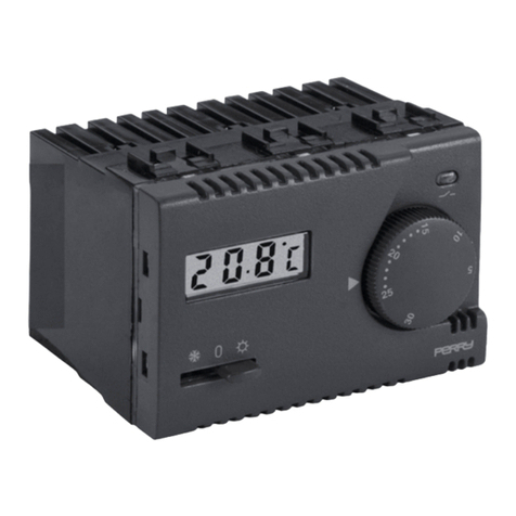
1TITE302/MC - Electronic thermostat with On-Off-Antifreeze control and input for night reduction
1TITE304/MC - Electronic thermostat for night reduction control on board
1TITE305/MC - Electronic thermostat with remote thermostat for floor heating;
night reduction control on board
5
1010
15
15
20
20
25
25
30
30
5
10
15
15
20
20
25
25
30
30
5
10
10
15
15
20
20
25
25
30
30
Reference index for temperature setting
Selector for controlling work mode, according to model:
1TITE302/MC - I
1TITE304/MC -
1TITE305/MC -
Load status signal LED:
alight = load inserted
5 °C ÷ 30 °C TE30 /MC1TI 2
"1TITE304/MC
(Alight - OFF - Antifreeze)
--0(Winter - OFF - Nighttime economy)
--0
0 °C ÷ 60 °C TE305/MC1TI
Knob with temperature scale:
Ins allation
and user
in tructions
t
s
Read this manual carefully before using the
product as it provides important guidelines
regarding safety, installation and use.
The manual must be preserved with care for
future reference.
PERFORMANCE DATA (according to model)
TECHNICAL DATA
Supply voltage: 230 V~ 50 ÷ 60 Hz
Type of action, disconnect and device: 1 / B / Electronic
Type of output relay with changeover contact NO / COM / NC:
voltage free - 8(2)A / 250 V~
Output connection (load): 2 or 3 conductors
Wire section at terminals: min. mm0,75 2- max. 2,5 mm2
Insulation type: Class II
Protection degree: IP 30
Pollution:
Temperature adjustment range
):
(excluding 1TITE305/MC from+5°Cto+30°C
Thermal gradient: max 1K/15 min.
Differential operation: T=0,7°C
Precision of reading ± 1 °C
Operating temperature limits: 0 °C ÷ + 50 °C
Reference standard for CE mark: LVD EN60730-2-9 EMC EN60730-2-9
normal
ERP Energy classification: ErP: Class I; 1% Reg. EU 811/2013
The recycling of materials will help to conserve natural resources. For more detailed
information about recycling of this product, please contact your local city office, your house
hold waste disposal service or the shop where you purchased the product.
By ensuring this product is disposed of correctly, you will help prevent potential negative
consequence for the environment and human health, which could otherwise be caused by
inappropriate waste handing of this product.
Instead, it shall be handed over to the applicable collection point for the recycling of
electrical and electronic equipment, such as for example:
DISPOSAL OF OLD ELECTRICAL & ELECTRONIC EQUIPMENT
- local collection points (waste collection centre, local recycling center, etc...).
This symbol on the product or its packaging to indicates that this product shall not be
treated as household waste.
- sales points, in case you buy a new and similar product
Temperature adjustment range
):
(only 1TITE305/MC from 0°Cto+60°C
External probe (only 1TITE305/MC): probe with 4 m of cable (supplied)
Antifreeze temperature (only 1TITE302/MC): +5 °C fix
COMPATIBILITY TO THE MOST COMMON RESIDENTIAL SERIES PLATES
IMPORTANT: for the assembly procedure of the thermostat with the chosen
residential plate, follow instructions contained in the specific compatibility
sheet contained in the package.
Examples of installation in heating systems
with a thermostat that controls:
A) Wall mounted boiler
B) Burner
C) Circulation pump or Motorized solenoid valve
D) Area solenoid valve
AB
C
DD
C
Attention: before starting any operations on the device, disconnect the 230V~ mains power supply
This appliance must be intended only for the use for which it was built. Any other use must be considered improper and dangerous.
Important: the installation and electrical connection of the devices and appliances must be implemented by person with electrotechnical expertise only and in conformity with current laws and
regulations. he manufacturer declines any liability for the use of products subject to special environmental and/or installation standards.T
The thermostat is not intended for use by persons (including children) with reduced physical, sensory or mental capabilities, or by those with a lack of experience and knowledge of the instructions,
unless they are supervised or have received the necessary instructions concerning use of the device by a person responsible for their safety.
Children should be supervised to ensure that they do not play with the device.
()limitable
()limitable
PE - DETIPE013 02/18
PE - DETIPE014EN 02/20
English
2 - WORKING FLUID MAXIMUM TEMPERATURE OF THE ENVIRONMENT LIMITATION
It is possible to preset from 16 °C to 24 °C, with 2 °C step, the maximum temperature value (excluding 1TITE305/MC).
It is possible to preset from 25 °C to 45 °C, with 5 °C step, the maximum temperature value (1TITE305/MC).
NB: the thermostat is supplied with the "range disc" preinstalled with pin in the neutral hole (no temperature limitation).
16 °C (25 °C)
18 °C (30 °C)
20 °C (35 °C)
22 °C (40 °C)
24 °C (45 °C)
Neutral hole
Holes for temperature set point limitation
Temperature limit setting or its subsequent modification
a) Rotate the knob anti-clockwise and pull it out.
b) Take out the “temperature range” disc and reinsert it by locating the maximum desired temperature
hole over the pin placed on thermostat .
(fig. 1)
c) Reinsert the and verify at the end of the anti-clockwise limit corresponding to 5°Cknob
N.B.:the values in parenthesis
refer to TE305/MC1TI
INSTALLATION INSTRUCTIONS
Holes
Pin
Rdange isc
Range disc seat range
Fig. 1
Knob
Index
AB C
FG
1-INSTALLATION EXAMPLE
Apply the chosen front Make the electrical connections Insert the thermostat
into the frame until it is blocked
Apply the two ledges to the frame Apply the chosen plate
Right ledge
Front
Plate
Thermostat body
E
Insert the knob
Correct knob
position
D
Set temperature lock
(only if desired)
Range disc
(if required based on the plate type)
(4 lateral blocking teeth)
Attention to the position of the
insertion pins of the ledges
Fasten the chosen frame
from the type 503 recess box
COMPATIBILITY TO THE MOST COMMON RESIDENTIAL SERIES PLATES
IMPORTANT: for the assembly procedure of the thermostat with the
chosen residential plate, also follow instructions contained in the
specific compatibility sheet contained in the package.
IMPORTANT! Left ledge
(0°C for 1TITE305/MC) with index, if different, re-insert the rotated by 180°.knob
Make sure to remove the 230V mains supply before proceeding with the installation
2
ELECTRICAL CONNECTIONS for 1TITE302/MC
Thermostat with inputs for controlling night temperature reduction, external (example )time switch
Switch mains supply off
Connect the power supply wires to the terminals n° (Line) n° (Neutr ).45and al
Connect the wires of the device to be controlled to the terminals: n° = com1mon
n°2=open
normally
n°3=normally closed
ELECTRICAL CONNECTIONS for 1TITE305/MC
Thermostat with external temperature probe for measuring the temperature of circulating liquid
in floor heating systems.
Switch mains supply off
Connect the power supply wires to the terminals n° (Line) n° (Neutr ).45and al
Connect the wires coming from the probe to the terminals: n° and n° (the probe is not polarised)67
For heavy inductive loads (pumps and solenoid valves) it is advisable to connect an RC filter in parallel with the load.
Fig. 3
- Example of connection to boiler and clock for night reduction control
time switch
230 V~
1TITE302/MC
Heater
Supply voltage (230V~)
Inputs for
night reduction control
230 V~
1TITE302/MC
Time switch with NO
contact, common to
all thermostats
1TITE302/MC
Fig. 6 - Example of connection to motorised valve and external probe
Supply voltage (230V~)
230 V~
1TITE305/MC
External probe
30 mm
4m
Ø 4.8 mm
ABS capsule
Fig. 7
PROBE INSTALLATION
•Insert the electric wire of the probe into a gaiter (e.g. rigid or corrugated pliable conduit)
according to the type of installation.
•
ATTEN :TION the connections to the
probe are network potential
Inputs for external probe
Multiple installations
Comfort
Open
Comfort
Conta tcOpen
Reduction
Closed
hours 0622hours
Fig. 2
Remote selection of "Comfort" or "Reduction" temperature
If you want to use remote control of “Comfort" or "Reduction" temperature,
connect the exterior contact to the terminals n° and n° of the thermostat67 (fig. 3 e fig. 4).
Fig. 4
ClosesN
Opens
Motorized
valve
Fig. 5 -Example of connection to motorised valve
Supply voltage (230V~)
230 V~
Motorized
valve
Closes
N
Opens
ELECTRICAL CONNECTIONS for 1TITE304/MC
Thermostat with on board night reduction control (-4°C from the set temperature group)
Switch mains supply off
Connect the power supply wires to the terminals n° (Line) n° (Neutr ).45and al
1TITE304/MC
N.B.: normally residential power supply used the unified colours "brown” for
the phase, "blue" for neutral (line return).
Terminal n° : connect the Neutral of network (return)5
Terminal n° : connect the Line of network (230 V~)4
1) Supply voltage (230V~)
For all thermostats
Besides all that has been mentioned above, in multiple installations (for
example offices, schools, houses, etc.) operated only by one clock for the
centralized night reduction, it is necessary to follow carefully the indications
below (fig. 4).
All terminals n° : connect in parallel with output of the time switch.71
All terminals n° : connect in parallel with output of the time switch.62
2) Connections for night reduction control
On board night reduction control (- 9°C from the set temperature group of the circulating liquid)
ATTEN ION:Tthe connections to the external reduction selection contacts are network potential.
Example
2°C0
16 °C
Fasten the sensor capsule at the measuring point.
Important: the sensor and its cable must not be accessible
to the user once installation has been completed.
3 - ()ELECTRICAL CONNECTIONS according to model
The manufacturer reserves the right to introduce any technical and/or constructive changes deemed necessary, with no prior notice.
For heavy inductive loads (pumps and solenoid valves) it is advisable to connect an RC filter in parallel with the load.
“Comfort” Temperature = external contact open
“Reduction” Temperature = external contact closed
Selecting “Reduction” temperature determines
a decrease of 4 °C with respect to the set
temperature value.
=opennormally
=normally closed
Connect the wires of the device to be controlled to the terminals: n° = com1mon
n° 2
n° 3
For heavy inductive loads (pumps and solenoid valves) it is advisable to connect an RC filter in parallel with the load.
=opennormally
=normally closed
Connect the wires of the device to be controlled to the terminals: n° = com1mon
n°2
n°3
Set temperature
3
Via Milanese, 11 - 22070 Veniano (Co) - Italy
Perry Electric S.r.l.
www.perry.it

This manual suits for next models

3

Other Perry Electric Thermostat manuals

Perry Electric TE540 User manual

Perry Electric

Perry Electric TE540 User manual

Perry Electric TE542 User manual

Perry Electric

Perry Electric TE542 User manual

Perry Electric V002 Series Guide

Perry Electric

Perry Electric V002 Series Guide

Perry Electric 1TX CR028WIFI Guide

Perry Electric

Perry Electric 1TX CR028WIFI Guide

Perry Electric TE541 User manual

Perry Electric

Perry Electric TE541 User manual

Perry Electric MODULE Series User manual

Perry Electric

Perry Electric MODULE Series User manual

Perry Electric RECESS Series User manual

Perry Electric

Perry Electric RECESS Series User manual

Popular Thermostat manuals by other brands

Ecobee 3 smarter wi-fi thermostat user manual

Ecobee

Ecobee 3 smarter wi-fi thermostat user manual

Ferroli TC PLUS Installation and use manual

Ferroli

Ferroli TC PLUS Installation and use manual

PR1 T715 operating instructions

PR1

PR1 T715 operating instructions

ICM Controls SC 5811 manual 

ICM Controls

ICM Controls SC 5811 manual 

ClimateMaster ATP32U03 user manual

ClimateMaster

ClimateMaster ATP32U03 user manual

Evco EC 3-181 operating instructions

Evco

Evco EC 3-181 operating instructions

Sygonix TOUCH TX5 operating instructions

Sygonix

Sygonix TOUCH TX5 operating instructions

Tekmar 508 User brochure

Tekmar

Tekmar 508 User brochure

Computherm Q7 operating instructions

Computherm

Computherm Q7 operating instructions

Polypipe UFH8ZMP user manual

Polypipe

Polypipe UFH8ZMP user manual

Wiser EER56000 Installer's guide

Wiser

Wiser EER56000 Installer's guide

Theben RAM 722 operating instructions

Theben

Theben RAM 722 operating instructions

TOTALINE TST-EGND06413SCS00 manual

TOTALINE

TOTALINE TST-EGND06413SCS00 manual

Everwell LP260 installation instructions

Everwell

Everwell LP260 installation instructions

Aprilaire 8555 owner's manual

Aprilaire

Aprilaire 8555 owner's manual

Carel UltraCella Assembly and installation

Carel

Carel UltraCella Assembly and installation

AURATON S03 RTH user manual

AURATON

AURATON S03 RTH user manual

Ascon tecnologic PM343 user manual

Ascon tecnologic

Ascon tecnologic PM343 user manual

manuals.online logo
manuals.online logoBrands
  • About & Mission
  • Contact us
  • Privacy Policy
  • Terms and Conditions

Copyright 2025 Manuals.Online. All Rights Reserved.