Perry 1TPTE501B Guide

PE - DETENN500 07/18
TERMOSTATI ELETTRONICI
INSTALLAZIONE DA PARETE O DA SEMINCASSO
SURFACE-MOUNTED OR SEMI FLUSH-MOUNTED
ELECTRONIC THERMOSTATS
THERMOSTATS ÉLECTRONIQUES POUR
MONTAGE EN SAILLIE OU SEMI-ENCASTRÉ
TERMOSTATOS ELECTRÓNICOS
DE PARED O SEMIEMPOTRADO
ELEKTRONISCHER THERMOSTAT FÜR WANDMONTAGE
ODER EINGELASSENE INSTALLATION

2
FR - Français
GB - English
ES - Espanòl
DONNÉES TECHNIQUES - NORMES D’INSTALLATION
MODE D’EMPLOI
DATOS TÉCNICOS - NORMAS DE INSTALACIÓN
INSTRUCCIONES PARA EL USUARIO
Page 17
Seite 24
Página 31
IT - Italiano
DATI TECNICI - ISTRUZIONI PER L’INSTALLAZIONE
MODO D’IMPIEGO
EN - English
TECHNICAL DATA - INSTALLATION GUIDELINES
USER INSTRUCTIONS
DE - Deutsch
TECHNISCHE DATEN - NORMEN FÜR DIE INSTALLATION
BEDIENUNGSANLEITUNG
Page 10
Pagina 3

3
DATI TECNICI
Tensione di alimentazione:
Tipo azione, disconnessione, apparecchio:
Tipo di uscita:
Collegamento utenza (carico):
Ingressi per comando remoto di “Riduzione”:
Sezione max dei fili ai morsetti:
Tipo di isolamento:
Grado di protezione:
Grado di inquinamento:
Limiti della temperatura di funzionamento:
Limiti della temperatura di stoccaggio:
Scala di regolazione temperatura:
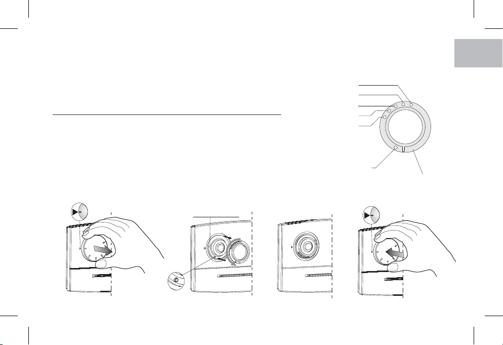
Limite di temperatura max impostabile:
Riduzione della temperatura:
Precisione di lettura della temperatura:
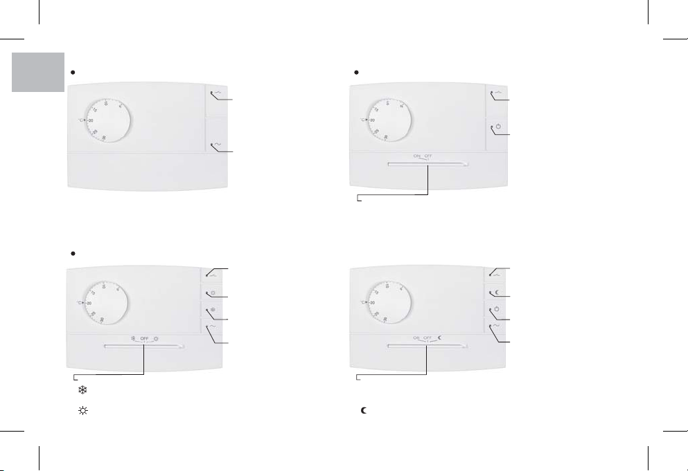
Tipo di funzionamento:
Funzionamento differenziale:
Gradiente termico:
Classificazione energetica ERP
Normative di riferimento per marcatura CE:
230 V~ 50 ÷ 60 Hz
1/ B / Elettronico
a relè con contatto in scambio NA / COM / NC
libero da potenziale - max 8(2) A / 250 V~
2 o 3 conduttori
per contatto libero da potenziale (mod. predisposti)
alimentazione = 2,5 mm2
contatto relè = 2,5 mm2
riduzione remota = 1,5 mm (mod. predisposti)
2
classe II
I30P
normale
0 °C ÷ +50 °C
-10 °C ÷ +65 °C
+5 °C ÷ +30 °C
16,18, 20, 22, 24 °C (impostabile con disco range)
- 4 °C dal set di temperatura impostato
± 1 °C
ON/OFF con differenziale
t = 0,4 °C (fisso)D
1 °K/15 min
ErP: Class I; 1% Reg. EU 811/2013
LVD EN60730-2-9 EMC EN60730-2-9
IT
Si raccomanda di leggere attentamente le presenti istruzioni di installazione ed uso e conservarle per future consultazioni.
Il costruttore si riserva la facoltà di introdurre tutte le modifiche tecniche e costruttive che riterrà necessarie senza obbligo
di preavviso.
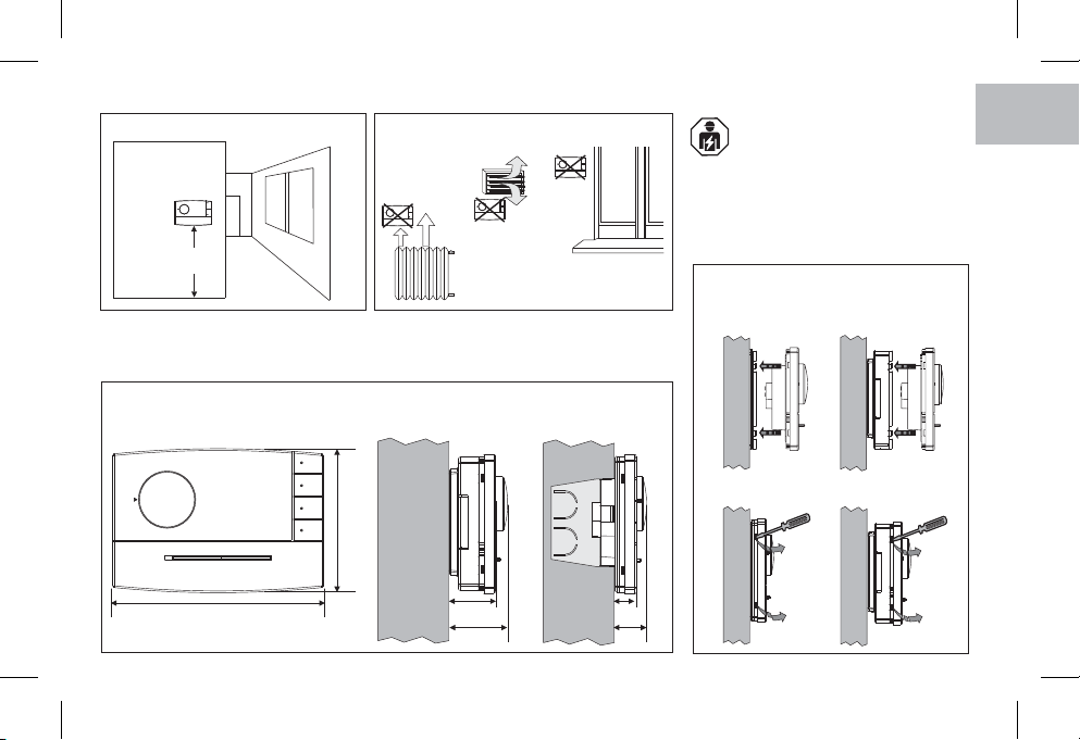
AVVERTENZE PER LA SICUREZZA
Assicurarsi di aver tolto l’alimentazione di rete 230V prima di procedere all’installazione o alla manutenzione.

4
G
B
IT
LED rosso stato del relè
(acceso = utenza attivata)
Ingresso per comando remoto di riduzione della temperatura
Modello con:
Commutatore:
INVERNO =funzionamento riscaldamento
OFF = termoregolazione disattivata
ESTATE =funzionamento raffrescamento
Commutatore:
ON= termoregolazione attivata
OFF = termoregolazione disattivata
= termoregolazione in riduzione (funzionamento -4 °C dal set di temperatura impostato)
LED verde alimentazione
(acceso = presenza di rete)
Ingresso per comando remoto di riduzione della temperatura
Modello con:
LED rosso stato del relè
(acceso = utenza attivata)
LED rosso termostato in funzione
(acceso = termoregolazione attivata)
Commutatore:
ON= termoregolazione attivata
OFF = termoregolazione disattivata
Ingresso per comando remoto di riduzione della temperatura
Modello con:
LED rosso stato del relè
(acceso = utenza attivata)
LED rosso funzione ESTATE
(acceso = raffrescamento)
LED verde alimentazione
(acceso = presenza di rete)
LED rosso funzione INVERNO
(acceso = riscaldamento)
Modello con:
LED rosso stato del relè
(acceso = utenza attivata)
LED verde alimentazione
(acceso = presenza di rete)
LED rosso termostato in funzione
(acceso = termoregolazione attivata)
LED rosso termoregolazione in
riduzione

5
ESEMPI DI INSTALLAZIONE
Installare preferibilmente il termostato a quota 1,50 ÷ 1,70 m dal pavimento; lontano da
sorgenti di calore, prese d'aria, porte o finestre e da quanto possa influenzarne il
funzionamento.
DIMENSIONI DI INGOMBRO
120
82
27,5
33,5
12,5
18,5
Fissaggio e rimozione del
termostato
modello a parete modello a semincasso
h 1,5 m
OK!
Importante: l'installazione ed il collegamento
elettrico del dispositivo devono essere
eseguiti solo da elettricista qualificato ed in
conformità alle norme e leggi vigenti. Il costruttore
non si assume alcuna responsabilità per quanto
concerne l’impiego di prodotti che debbano seguire
particolari norme di ambiente e/o installazione.
IT

6
INSTALLAZIONE DEL TERMOSTATO
Modelli per installazione a SEMINCASSO
Supporto per installazione a semincasso del termostato
Modelli per installazione a PARETE
Base per installazione a parete del termostato
Per assicurare un corretto
montaggio del termostato al
supporto o alla base a parete,
gli stessi non devono
presentare incurvature dovute
all’eccessivo serraggio delle
viti di fissaggio nella scatola
tonda o rettangolare incassata
a muro.
A Fori di fissaggio del supporto:-
su scatola ad incasso tonda o rettangolare
B Passaggio fili da:-
Scatola ad incasso tonda o rettangolare,
tubo corrugato (per modello a parete)
C Fori di fissaggio della base:-
a parete, su scatola ad incasso tonda o rettangolare
D Dentini di fissaggio termostato-
E Passaggi per fili da canalina a parete (asportare diaframma)-
(per fissare direttamente la base a muro utilizzare appositi
tasselli non forniti)
D
D
B
A
A
A
A
E
B
D
CE
D
E
C
G
B
IT

7
disattivare la tensione di rete
Collegare l’alimentazione di rete 230V~ ai morsetti:
n° =1Linea
n° =2Neutro
Collegare i fili del dispositivo da comandare ai morsetti:
n° = contatto normalmente aperto3
n° = comune4
n° = contatto normalmente chiuso5
Importante: con forti carichi induttivi (pompe ed elettrovalvole)
si consiglia di collegare un filtro RC in parallelo al carico.
Collegamenti per la selezione remota della temperatura
"Riduzione" solo su modelli predisposti
Qualora si desideri utilizzare la selezione remota della
temperatura “Comfort" o "Riduzione", provvedere al
collegamento del contatto esterno (privo di potenziale) ai
morsetti: n° e n° del termostato.67
COLLEGAMENTI ELETTRICI
1
2
3
4
5
6789
230 V ~
N
L
Ingresso riduzione
(modelli predisposti)
OkOk
ResetReset
ProgProg
YYMMChCh
DayDay
1234567
SEC
ON
1234567
SEC
ON
esempio
Interruttore orario
1
2
3
4
5
6789
230 V ~
N
L
OkOk
ResetReset
ProgProg
YYMMChCh
DayDay
1234567
SEC
ON
1234567
SEC
ON
esempio
Interruttore orario
Elettrovalvola motorizzata
N
Apre
Chiude
Caldaia
Ingresso riduzione
(modelli predisposti)
IT

8
Interruttore orario
1
2
3
4
5
6789
OkOk
ResetReset
ProgProg
YYMMChCh
DayDay
1234567
SEC
ON
1234567
SEC
ON
1
2
3
4
5
6789
TERMOSTATO
TERMOSTATO
230 V ~
N
L
Principio di funzionamento del comando a bordo o remoto di riduzione della temperatura(per modelli predisposti)
La selezione della temperatura di “Riduzione”
determina una riduzione di 4 °C, rispetto al
valore di set impostato della temperatura.
Temperatura “ ”Comfort Contatto remoto aperto
Temperatura “ ”Riduzione Contatto remoto chiuso
Contatto
T set (Comfort) = 20 °C
24 °C
Temperatura
ambiente
16 °C
Aperto
Riduzione
Chiuso
Aperto
h 22:00 h 6:00
Esempio
Installazioni multiple
Nelle installazioni multiple (vedi uffici, scuole, abitazioni,
ecc.) comandate per la riduzione notturna centralizzata
da un solo interruttore orario, è necessario attenersi
scrupolosamente alle seguenti indicazioni (figura a lato).
Per tutti i termostati
Alimentazione (230V~)
Tutti i morsetti n° : collegare la Linea1
Tutti i morsetti n° : collegare il Neutro2
Collegamenti per comando riduzione notturna
Tutti i morsetti n° : collegare in parallelo con uscita6M1
del comando remoto (interruttore orario).
Tutti i morsetti n° : collegare in parallelo con uscita7M2
del comando remoto (interruttore orario).
Nota per l’installatore: nell’esecuzione dei collegamenti elettrici, nel caso di installazione a parete senza scatola incasso, prestare particolare attenzione
affinché il cablaggio sia ben disposto e non interferisca con la corretta chiusura del termostato.
Temperatura “ ”Comfort Commutatore in posizione ON
Temperatura “ ”Riduzione Commutatore in posizione
M1
M2
G
B
IT

9
LIMITAZIONE TEMPERATURA MASSIMA DELL’AMBIENTE
Foro neutro
16 °C
18 °C
20 °C
22 °C
24 °C
Fori per limitazione set di temperatura
(± 0,5 °C)
Disco range
E' possibile prefissare da 16 °C a 24 °C, con step di 2 °C, il massimo valore di temperatura
impostabile.
N.B.: il termostato viene fornito con il "disco range" preinstallato con il perno nel foro
neutro (nessuna limitazione di temperatura).
Impostazione del limite di temperatura o sua successiva modifica
a) Ruotare la manopola in corrispondenza dei (30 °C per modelli in funzionamento5°C
Estate) ed estrarla.
b-c) Estrarre il "disco range", quindi reinserirlo facendo corrispondere il foro relativo alla
temperatura massima desiderata con il perno situato sul termostato.
d) Reinserire la manopola avendo cura di inserirla nella medesima posizione che aveva in
precedenza; posizione dei (30 °C per modelli in funzionamento Estate) in
5°C
corrispondenza dell’indice presente sul frontale del termostato.
5
5
a) b) c) d)
Perno
Sede disco range
IT

G
B
EN
10
DATI TECNICIDATI TECNICI
TECHNICAL DATA
Supply voltage:
Type of action, disconnect and device:
Type of output:
Output connection (load):
Inputs for “Reduction” control, remote:
Maximum wire section at terminals:
Insulation type:
Protection degree:
Pollution:
Operating temperature limits:
Storage temperature limits:
Temperature adjustment range:
Settable max. temperature limit:
Reduction temperature:
Precision of reading of the temperature:
Operation:
Differential operation:
Thermal gradient:
ERP Energy classification:
Reference standard for CE mark:
230 V~ 50 ÷ 60 Hz
1/ B / Electronic
relay with changeover contact NO / COM / NC
voltage free - max 8(2)A / 250 V~
2 or 3 conductors
for voltage free contact (models where provided for)
supply voltage = 2,5 mm2
relay contact = 2,5 mm2
reduction remote = 1,5 mm2(models where provided for)
Class II
I30P
Normal
0 °C ÷ +50 °C
-10 °C ÷ +65 °C
+5 °C ÷ +30 °C
16,18, 20, 22, 24 °C (settable with range disc)
- 4 °C from temperature setpoint
± 1 °C
ON/OFF with differential
Dt = 0,4 °C (fixed)
1 °K/15 min
ErP: Class I; 1% Reg. EU 811/2013
LVD EN60730-2-9 EMC EN60730-2-9
SAFETY PRECAUTIONS
Before starting any operations on the device, disconnect the 230V~ mains power supply
Read this manual carefully before using the product as it provides important guidelines regarding safety, installation and use.
The manual must be preserved with care for future reference. The manufacturer reserves the right to introduce any technical
and/or constructive changes deemed necessary, with no prior notice.

EN
Relay status red LED
(alight = load ON)
Input for remote control temperature reduction
Model with:
Switch
WINTER=heating operation
OFF = thermoregolation OFF
SUMMER=cooling operation
Switch:
ON= thermoregolation ON
OFF = thermoregolation OFF
= thermoregolation in reduction (operation -4°C from the set temperature)
Supply voltage green LED
(alight = power ON)
Input for remote control temperature reduction
Model with:
Relay status red LED
(alight = load ON)
Thermostat On red LED
(alight = thermoregulation ON)
Switch:
ON= thermoregolation ON
OFF = thermoregolation OFF
Input for remote control temperature reduction
Model with:
Relay status red LED
(alight = load ON)
Summer operation red LED
(alight = cooling)
Supply voltage green LED
(alight = power ON)
Winter operation red LED
(alight = heating)
Model with:
Relay status red LED
(alight = load ON)
Supply voltage green LED
(alight = power ON)
11
Thermoregolation reduction red LED
Thermostat On red LED
(alight = thermoregulation ON)

INSTALLATION EXAMPLES
Fixing and removing the
thermostat
12
Install the thermostat at a height of 1,5 m ÷ 1,7 m from the floor, far from heat sources, air
vents, doors or windows and anything else that could affect its operation.
DIMENSIONS
120
82
27,5
33,5
12,5
18,5
model
surface mounting
model
semi flush mounting
h 1,5 m
OK!
Important: t lhe installation and electrica
connections of devices and appliances must
be implemented by person with
electrotechnical expertise only and in conformity
with current laws and regulations. The manufacturer
declines any liability in connection with the use of
products subject to special environmental and/or
installation standards.
G
B
EN

13
THERMOSTAT INSTALLATION
Models for SEMI FLUSH mounting
Support for thermostat semi flush mounting
To ensure correct fitting of the
thermostat to the support or
surface-mounted base, make
sure the latter are not distorted
by overtightening of the fixing
screws in the round or
rectangular flush-mounted
box.
(to fix the base directly to the wall, use special plugs
not supplied)
A - Holes for fixing the support:
to round or rectangular flush-mounted box
B - Passage of wires from:
Round or rectangular flush-mounted box,
corrugated tube (for surface-mounted model)
C - Holes for fixing the base:
to wall, to round or rectangular flush-mounted box
D - Thermostat fixing teeth
E - Passages for wires from wall raceway (remove diaphragm)
D
D
B
A
A
A
A
Base for thermostat surface mounting
Models for SURFACE mounting
E
B
D
CE
D
E
CEN

14
Switch mains supply off
Connect 230V ~ power supply to the terminals:
n° =1Line
n° =2Neutral
Connect the controlled device to the terminals:
n° = normally open contact3
n° = common4
n° = normally closed contact5
IMPORTANT: for heavy inductive loads (pumps and solenoid
valves) it is advisable to connect an RC filter in parallel with the
load.
Connections for the temperature "Reduction" remote
control (models where provided for)
If you want to use remote control of or“Comfort" "Reduction"
temperature, connect the exterior contact (potential-free) to the
terminals: n° and n° of the thermostat.67
ELECTRICAL CONNECTIONS
1
2
3
4
5
67 89
230 V ~
N
L
Reduction input
(models where
provided for)
OkOk
ResetReset
ProgProg
YYMMChCh
DayDay
1234567
SEC
ON
1234567
SEC
ON
example
time switch
1
2
3
4
5
67 89
230 V ~
N
L
OkOk
ResetReset
ProgProg
YYMMChCh
DayDay
1234567
SEC
ON
1234567
SEC
ON
example
time switch
Motorized valve
N
Open
Close
Heater
Reduction input
(models where
provided for)
G
B
EN

15
Time switch
1
2
3
4
5
6789
1
2
3
4
5
6789
THERMOSTAT
THERMOSTAT
230 V ~
N
L
Working principle of the onboard or remote temperature reduction control(models where provided for)
Selecting “Reduction” (Economy)
temperature determines a decrease of 4 °C
with respect to the set temperature value.
Open remote c conta t
Closed remote contact
Conta tc
T set (Comfort) = 20 °C
24 °C
Ambient
temperature
16 °C
Open
R du ionect
Closed
Open
“ ” TemperaturComfort e
“ ” TemperaturR du ionect e
h 22:00 h 6:00
Example
Multiple installations
Besides all that has been mentioned above, in multiple
installations (for example offices, schools, houses,
etc.) operated only by one clock for the centralized
night reduction, it is necessary to follow carefully the
indications below.
For all thermostats
Supply voltage (230V~)
All terminals n° : connect the Line1
All terminals n° : connect the Neutral2
Connections for night reduction control
All terminals n°. : connect in parallel with output6M1
of the remote control (time switch)
All terminals n°. : connect in parallel with output7M2
of the remote control (time switch)
Note for the contractor: make the electrical connections taking particular care in the event of surface mounting without box that the
wires are correctly arranged and do not hinder a proper fit between the body and the base.
Switch in position ON
Switch in position
“ ” TemperaturComfort e
“ ” TemperaturR du ionect e
OkOk
ResetReset
ProgProg
YYMMChCh
DayDay
1234567
SEC
ON
1234567
SEC
ON
M1
M2
EN

16
LIMITATION OF THE MAXIMUM ROOM TEMPERATURE
Neutral hole
16 °C
18 °C
20 °C
22 °C
24 °C
Holes for temperature setpoint limitation
(± 0,5 °C)
Range disc
It is possible to preset from 16 °C to 24 °C, with 2 °C step, the maximum temperature value.
NB: the thermostat is supplied with the "range disc" preinstalled with pin in the neutral hole
(no temperature limitation).
Temperature limit setting or its subsequent modification
a) Turn the knob to the (30 °C for models in Summer mode) mark; then remove the5°C
knob.
b-c) Take out the “temperature range” disc and reinsert it by locating the maximum
desired temperature hole over the pin placed on thermostat.
d) Replace the knob, making certain it is positioned as before: (30 °C for models in
5°C
Summer mode) position coinciding with the index on the front of the case.
5
5
a) b) c) d)
Pin
Range disc seat
G
B
EN

DONNÉES TECHNIQUES
Tension d’alimentation:
Type d’action, déconnexion et appareil:
Type de sortie:
Connexion asservissement (charge):
Entrées pour commande “Réduction”, à distance:
Section maximum des fils aux bornes:
Type d’isolation:
Degré de protection:
Pollution:
Limites de la température de fonctionnement:
Limites de la température de stockage:
Echelle de réglage de la température:
Limite de température maxi programmable:
Réduction de la température:
Précision de lecture de la température:
Fonctionnement:
Fonctionnement différentiel:
Gradient thermique:
Classement énergétique ERP:
Normatives de référence pour le label CE:
230 V~ 50 ÷ 60 Hz
1/ B / Electronique
A relais avec contact d’échange NO / COM / NF
libre de potentiel - max 8(2)A / 250 V~
2 ou 3 conducteurs
pour contact libre de potentiel (modèles pré-équipés)
alimentation = 2,5 mm2
contact relais = 2,5 mm2
réduction à distance = 1,5 mm (modèles pré-équipés)
2
Classe II
I30P
Normale
0 °C ÷ +50 °C
-10 °C ÷ +65 °C
+5 °C ÷ +30 °C
16,18, 20, 22, 24 °C (réglable à l'aide du disque gamme de température)
- 4 °C de la plage de température programmée
± 1 °C
ON/OFF avec différentiel
t = 0,4 °C (fixe)D
1 °K/15 min
ErP: Class I; 1% Reg. EU 811/2013
LVD EN60730-2-9 EMC EN60730-2-9 17
Il est recommandé de lire avec attention les présentes instructions d'installation et d'utilisation et de les conserver pour de
futures consultations. Le fabricant se réserve la faculté d'apporter toutes les modifications techniques et de construction qu'il
jugera nécessaires sans obligation de préavis.
MESURES DE SÉCURITÉ
Avant d'effectuer tout travail sur le dispositif, couper l'alimentation du réseau 230V~.
FR

18
Rouge (DEL) état du relais
(allumée = charge activée)
Entrée pour commande à distance de la réduction de la température
Modèle avec:
Commutateur:
HIVER =fonctionnement réchauffement
OFF = réglage thermique désactivé
ETÉ =fonctionnement réfroidissement
Commutateur:
ON= réglage thermique activé
OFF = réglage thermique désactivé
= réglage thermique en réduction (-4°C référé à la température programmée)
Vert (DEL) alimentation
(allumée = présence du réseau)
Entrée pour commande à distance de la réduction de la température
Modèle avec:
Rouge (DEL) état du relais
(allumée = charge activée)
Rouge (DEL) thermostat en service
(allumée = réglage thermique activé)
Commutateur:
ON= réglage thermique activé
OFF = réglage thermique désactivé
Entrée pour commande à distance de la réduction de la température
Modèle avec:
Rouge (DEL) état du relais
(allumée = charge activée)
Rouge (DEL) fonctionnement ETÉ
(allumée = réfroidissement)
Vert (DEL) alimentation
(allumée = présence du réseau)
Rouge (DEL) fonctionnement HIVER
(Allumée = réchauffement)
Modèle avec:
Rouge (DEL) état du relais
(allumée = charge activée)
Vert (DEL) alimentation
(allumée = présence du réseau)
Rouge (DEL) thermostat en service
(allumée = réglage thermique activé)
Rouge (DEL) réglage thermique
en réduction
G
B
FR

19
EXEMPLES D’INSTALLATION
Fixation et démontage du
thermostat
Si possible, installer le thermostat à 1,50 ÷ 1,70 m du sol et à bonne distance des sources
de chaleur, des prises d’air, des portes ou des fenêtres et de tout ce qui peut agir sur le
fonctionnement.
DIMENSIONS DU THERMOSTAT
120
82
27,5
33,5
12,5
18,5
modèl en saillie modèl semi-encastré
h 1,5 m
OK!
Important: 'installation et le branchementl
électrique des dispositifs et appareils
doivent être effectués par un électricien
qualifié et conformément aux normes et aux lois
en vigueur. Le constructeur n'assume aucune
responsabilité en ce qui concerne l'utilisation des
produits qui doivent suivre des normes
particulières concernant l'environnement et/ou
l'installation.
FR

INSTALLATION DU THERMOSTAT
A Trous de fixation de la plaque:-
sur boîte à encastrer ronde ou rectangulaire
B Passage des fils de:-
boîte à encastrer ronde ou rectangulaire,
gaine (pour mod. à montage mural)
C Trous de fixation de la base:-
en saillie ou sur boîte à encastrer ronde ou rectangulaire
D Dents de fixation du thermostat-
E Passages pour fils sous gaine en saillie (enlever le diaphragme)-
20
Modèles pour montage SEMI-ENCASTRÉ
Plaque pour montage semi-encastré du thermostat
Modèles pour montage EN SAILLIE
Pour un montage correct du
thermostat sur la plaque ou la
base murale, celles-ci ne
doivent pas être courbées à
cause d'un serrage excessif
des vis de fixation à la boîte
ronde ou rectangulaire
encastrée dans le mur.
(pour fixer directement la base au mur, utiliser des chevilles
appropriées non fournies)
D
D
B
A
A
A
A
Base pour montage en saillie du thermostat
E
B
D
CE
D
E
C
G
B
FR
Table of contents
Languages:
Other Perry Thermostat manuals