Perry 1TPTE400-B User manual

With LCD display and battery power supply - 3 V
Avec afficheur LCD et alimentation par batteries-3V
Mit LCD-display und Batteriebetrieb-3V
Con display LCD e alimentazione a pile - 3 V
Con pantalla LCD y alimentación por pilas - 3V
WALL MOUNTING ELECTRONIC DIGITAL THERMOSTAT
THERMOSTAT ELECTRONIQUE DIGITAL POUR MONTAGE EN SAILLIE
ELEKTRONISCHER DIGITAL RAUMTHERMOSTAT WANDMONTAGE
TERMOSTATO ELETTRONICO DIGITALE DA PARETE
TERMOSTATO ELECTRONICO DIGITAL DE PARED
lm - DETPNN003 04/03
Model with ON - Reduction - OFF switch
Modèle avec commutateur ON - Réduction - OFF
Modell mit Umschalter ON - Nachtbetrieb - OFF
Modello con commutatore ON - Riduzione - OFF
Modelo con conmutador ON - Reducción - OFF
Model with Winter - OFF - Summer switch
Modèle avec commutateur Hiver - OFF - Eté
Modell mit umschalter Winter - OFF - Sommer
Modello con commutatore Inverno - OFF - Estate
Modelo con conmutador Invierno - OFF - Verano

I - Italiano
D - Deutsch
F - Français
GB - English
E - Espanòl
2
DATI TECNICI - ISTRUZIONI PER L’INSTALLAZIONE
MODO D’IMPIEGO
TECHNICAL DATA - INSTALLATION GUIDELINES
USER INSTRUCTIONS
DONNÉES TECHNIQUES - NORMES D’INSTALLATION
MODE D’EMPLOI
TECHNISCHE DATEN - NORMEN FÜR DIE INSTALLATION
BEDIENUNGSANLEITUNG
DATOS TÉCNICOS - NORMAS DE INSTALACIÓN
INSTRUCCIONES PARA EL USUARIO
Page 3
Page 9
Seite 15
Pagina 21
Página 27

Supply voltage:
Output connection (load):
W
Pollution:
Temperature adjustment range:
Temperature display range:
Reduction temperature:
Precision of reading of the temperature:
Ambient temperature indicator resolution:
Differential operation:
Battery life:
Time remaining from battery low indication:
Thermal gradient:
(directives 73/23/CEE - 89/336/CEE).
Type of action, disconnect and device:
Type of output:
ire section at terminals:
Insulation type:
Protection degree:
Operating temperature limits:
Storage temperature limits:
Reference standard for CE mark:
N° 2 alkaline batteries 1,5V each type AAA (LR03)
1/ B / Electronic
Relay with changeover contact NO / COM / NC
voltage free - max 8(2)A / 250 V
2 or 3 conductors
min. 0,75 mm ÷ max. 1,5 mm
Class II
Normal
0 °C ÷ +50 °C
-10 °C ÷ +65 °C
+5 °C ÷ +30 °C
-5 °C ÷ +39 °C
-4 °C from the set temperature (only for predisposed model)
± 0,5 °C
0,1 °C
t selectable: = 0,3 °C - 0,5 °C - 0,7 °C - 0,9 °C
1 °K/15 min
1 year min.
About 1 month
LVD EN60730-2-9
EMC EN60730-2-9
~
22
IP30
D
1 - TECHNICAL DATA
3
G
B
ENGLISH

-
-
Room temperature display
Temperature setting display
Temperature setting knob
Load status LED (brief flashes = load ON)
Battery low LED (brief flashes = battery low)
2 - SIGNALS AND CONTROLS
Temperature display
The display normally shows the detected room tempe-
rature.
When setting the temperature with the knob, the display
shows the set temperature; a few seconds after the end
of the operation the room temperature is shown again.
In mode the set
temperature shown is the reduced temperature
“Reduction” (only predisposed model)
(-4 °C
from the )
set temperature . OFF
ON
25
5
15
20
30
10
4
G
B
-5.0 °c 39.0 °cor
= “room temperature outside
display range”
Blinking signals
= “probe fault” (relay deactivated)
---
Operation mode switch (according to model)
Model with reduction temperature
Thermoregulation
OFF
Thermoregulation
ON
Operation with temperature
(-4 °C from the set temperature)
reduction
Model with Winter/Summer operation
Thermoregulation
OFF
Summer operation
(
Cooling)
Winter operation
(Heating)
OFF
OFF
ON

5
80
18
120
!
!
+
OFF
ON
+
OFF
ON
+
OFF
ON
h 1,5 m
OK!
+
OFF
ON
Dimensions
3 - INSTALLATION GUIDELINES
Installation of thermostat: independent - fixed
!
!
Wall mounting.
Install the thermostat at a height of 1,5 m ÷ 1,7 m from
the floor, far from heat sources, air vents, doors or win-
dows and anything else that could affect its operation.
Important: installation and electrical connections of devi-
ces and appliances must be carried out by skilled people
and in compliance with current regulations.
The manufacturer declines any liability in connection with
the use of products subject to special environmental
and/or installation standards.
G
B

6
4 - FIXING BASE TO THE WALL
A
B
C
D
- for round box (diam. 60mm) with claws
- for round or square box (with screws)
- for 3 spaces rectangular box (with screws)
- knockouts allowing entry of wires (flexible only)
N. B.: To ensure the thermostat is fitted correctly to the wall-mounted base, care must be taken to ensure that the base is not
distorted by screwing the back box too tightly to the wall.
!
!
Isolate the controlled appliance from the electrical power supply.
Fix with screws the base of the thermostat to the back box (or to the
wall), using the pairs of holes provided.
5 - ELECTRICAL CONNECTIONS
Note for the contractor
Make the electrical connections taking particular care in the event
of surface mounting without box that the wires are correctly arran-
ged and do not hinder a proper fit between the body and the base.
!
!
Turn off the electrical power to the wiring.
Connect the controlled device to the terminals:
n° - common
n° - normally open contact
n° - normally closed contact
1
2
3
G
B
32
1
Burner
321
230V~
L
N
NOpenClose
Motorized valve
Examples of electrical connections
CNC NO
CNC NO

7
7 - FIXING THE THERMOSTAT TO BASE
Fit the body to the base as shown in fig. A.
Exert light pressure until you hear the click of the attachment
hooks.
To remove the insert a smal screwdriver as a lever in
the position corresponding to the attachment hooks (fig. B).
thermostat
6 - TEMPERATURE DIFFERENTIAL VALUE SETTING - t
The thermostat operates in differential
modes (ON-OFF) with a modifiable
differential value (factory-set to 0,5 °C).
position the
dip-switches, located on the back of the
thermostat, for the required differential
value.
Changing the differential:
8 - INSERTING OR REPLACING BATTERIES
!Open the cover of the battery compartment.
Replace the dead batteries with two 1,5 V
type , paying
attention to their polarity.
Close the cover.
!
!
AAA (LR03) alkaline batteries
Attachment hooks
fig. A fig. B
G
B
ON
12
ON
12
ON
12
ON
12
Dt = 0,3 °C Dt = 0,5 °C Dt = 0,7 °C Dt = 0,9 °C
25
5
15
20
30
10
OFF
ON
25
5
15
20
30
10
OFF
ON

8
24°22° 20° 18° 16°
Neutral
9 - LIMITATION OF THE MAXIMUM ROOM TEMPERATURE
The maximum adjustable value of the temperature setting can be limited as
follows:
!
!
!
!
turn the knob to the 5 °C mark; then remove the knob (fig. A)
replace the knob, making certain it is positioned as before: 5 °C position coinciding
with the index on the front of the case (fig. D).
extract the JUMPER from its housing (fig. B)
Insert the JUMPER in the holes corresponding to the desired temperature (fig. C)
fig. B
fig. A
fig. C fig. D
G
B
5
5
++ + +
25
5
15
20
30
10
25
5
15
20
30
10
25
5
15
20
30
10
25
5
15
20
30
10

Tension d’alimentation:
Connexion asservissement (charge):
Section des fils aux bornes
Type d’isolation
Degré de protection
Pollution:
Echelle de réglage de la température:
Echelle de visualisation de la température:
Réduction de la température:
Précision de lecture de la température:
Risolution indicateur de la température ambiante:
Fonctionnement différentiel:
Gradient thermique
Autonomie de fonctionnement:
Autonomie de la signalisation de batterie
déchargée:
(directives 73/23/CEE - 89/336/CEE).
Type d’action, déconnexion et appareil:
Type de sortie:
:
:
:
Limites de la température de fonctionnement:
Limites de la température de stockage:
Normatives de référence pour le label CE:
N° 2 piles alcalines 1,5V mini stylo type AAA (LR03)
1/ B / Electronique
A relais avec contact d’échange NO / COM / NF
libre de potentiel - max 8(2)A / 250 V
2 ou 3 conducteurs
min. 0,75 mm ÷ max. 1,5 mm
Classe II
Normale
0 °C ÷ +50 °C
-10 °C ÷ +65 °C
+5 °C ÷ +30 °C
-5 °C ÷ +39 °C
-4 °C de la temperature programmée
± 0,5 °C
0,1 °C
t sélectionnable: = 0,3 °C - 0,5 °C - 0,7 °C - 0,9 °C
1 °K/15 min
1 année minimum
Environ 1 mois
LVD EN60730-2-9
EMC EN60730-2-9
~
22
IP30
(seul modèle prédisposé)
D
1 - DONNÉES TECHNIQUES
FRANÇAIS
F
9

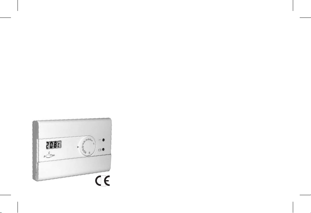
Manette de réglage de la température
LED état de la charge (clignotements courts = charge activée)
LED batterie déchargée (clignotements courts = batterie déchargée)
F
10
2 - COMMANDES ET SIGNALISATIONS
- Visualisation température ambiante
- Visualisation température en cours de paramétrage
Visualisation de la température
L’afficheur visualise normalement la température am-
biante mesurée. Lors du paramétrage de la température
à l’aide de la manette, l’afficheur visualise la température
en cours de paramétrage; quelques secondes après la
fin de l’opération, la température ambiante s’affiche de
nouveau. En modalité de fonctionnement
la température en cours de
paramétrage visualisée est la température réduite (
“Réduction”
(seul modèle prédisposé)
-4 °C
référé à la température programmée). OFF
ON
25
5
15
20
30
10
Signalisations clignotants
-5.0 °c 39.0 °cou
= “température ambiante hors
champ d’affichage”
= “sonde en panne” (relais inhibé)
---
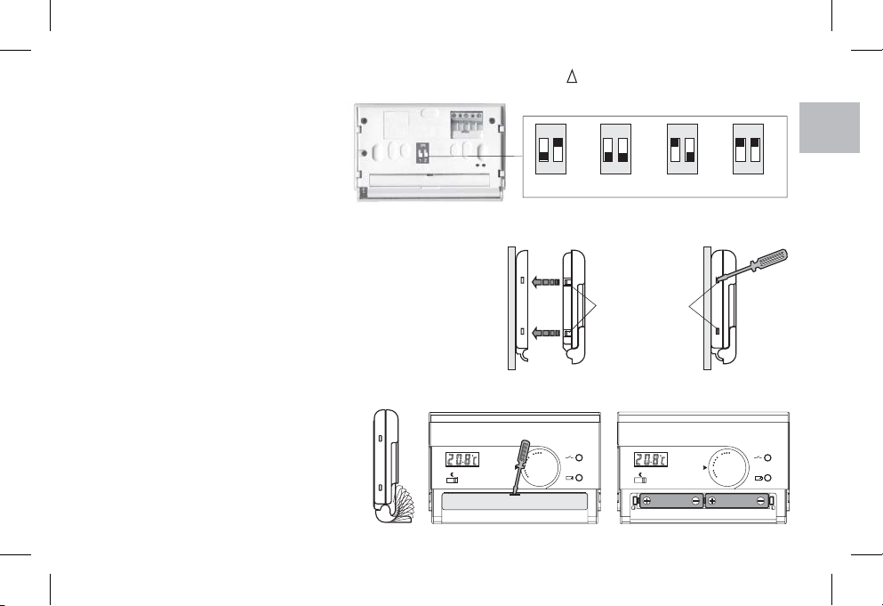
Commutateur du mode de fonctionnement (selon le modèle)
Modèle avec température de réduction
Réglage thermique
activé
Réglage thermique
désactivé
Fonctionnement avec température de
(-4 °C référé à la température programmée)
réduction
Modèle avec fonctionnement Hiver/Eté
Réglage thermique
désactivé
Fonctionnement Eté
(
Réfroidissement)
Fonctionnement Hiver
(Réchauffement)
OFF
OFF
ON

11
Dimensions
3 - NORMES D’INSTALLATION
Installation du thermostat: indépendant - fixe
!
!
En saillie.
Installer le thermostat à 1,5 m ÷ 1,7 m. du sol, loin de
sources de chaleur, de prises d’air, de portes ou de
fenêtres et de tout ce qui peut agir sur le fonctionnement.
Important: l’installation et le branchement èlectrique des
dispositifs et appareils doivent être effectués par du per-
sonnel qualifié et conformément aux normes et aux régle-
mentations en vigueur.
Le constructeur décline toute responsabilité en ce qui con-
cerne l’utilisation de produits devant respecter des nor-
mes particulières quant au milieu ambiant et/ou à
l’installation.
F
80
18
120
!
!
+
OFF
ON
+
OFF
ON
+
OFF
ON
h 1,5 m
OK!
+
OFF
ON

4 - FIXATION DE LA BASE AU MUR
A
B
C
D
- pour boîte ronde (diam. 60 mm) à griffes
-
-
- zones amovibles pour l’entrée des fils (uniquement flexibles)
pour boîte ronde ou carrée (à vis)
pour boîte rectangulaire à 3 postes (à vis)
N. B.: Pour un montage correct du thermostat à la base murale, celle-ci ne doit pas présenter de courbures dues au
serrage excessif des vis de fixation dans la boîte encastrée dans le mur.
!
!
Mettre le dispositif à commander hors tension.
Fixer à vis la base du thermostat à la boîte à encastrer (ou au mur) en
utilisant les paires de trous prévues à cet effet.
5 - BRANCHEMENTS ELECTRIQUES
Note pour l’installateur
Exécuter les branchements électriques en prêtant une attention par-
ticulière en cas de montage en saillie sans boîte à encastrer, en fai-
sant en sorte que le câblage soit bien posé et qu’il ne gêne pas la
bonne fermeture du corps. Chaudière
230V~
L
N
NOuvert
Fermé
Vanne motorisée
32
1
321
CNF NO
CNF NO
Exemples de branchements électriques
!
!
Désactiver la tension du réseau.
Brancher le dispositif à commander aux bornes:
n° - commun
n° - contact normalement ouvert
n° - contact normalement fermé
1
2
3
12
F

Dents de fixage
13
7 - FIXATION DU THERMOSTAT A LA BASE
Appliquer le thermostat à la base comme indiqué en fig. A.
Exercer une légère pression jusqu’à entendre le
déclenchement des dents de fixation.
Pour enlever le , on doit faire pression avec un petit
tournevis où se trouvent les dents de fixage (fig. B).
thermostat
Le thermostat fonctionne en mode diffé-
rentiel (ON-OFF) avec une valeur du dif-
férentiel modifiable (fixèe en usine à 0,5 °C).
positionner
les commutateurs multiples (dip-switch) à
l’arrière du thermostat, pour la valeur
suohaitée.
Modification du différentiel:
8 - INSERTION ET REMPLACEMENT DES PILES D’ALIMENTATION
6 - IMPOSTATION DU VALEUR DU DIFFERENTIEL DE TEMPÉRATURE -t
!Ouvrir le couvercle de logement des piles.
Substituer les piles usées avec deux
de 1,5 V type en
faisant attention à la polarité.
Fermer le couvercle.
!
!
piles
alcalines AAA (LR03)
fig. A fig. B
F
ON
12
ON
12
ON
12
ON
12
Dt = 0,3 °C Dt = 0,5 °C Dt = 0,7 °C Dt = 0,9 °C
25
5
15
20
30
10
OFF
ON
25
5
15
20
30
10
OFF
ON

9 - LIMITATION DE LA TEMPÉRATURE AMBIANTE MAXIMALE
5
5
++ + +
fig. B fig. C
fig. A
fig. D
25
5
15
20
30
10
25
5
15
20
30
10
25
5
15
20
30
10
25
5
15
20
30
10
14
24°22° 20° 18° 16°
Neutral
Il est possible de limiter la valeur maximum de température en agissant comme
suit:
!
!
!
!
mettre la manette au niveau de 5 °C; sortir la manette (fig. A)
remettre la manette en place en veilant à l’introduire dans la même position que celle
d’avant: position des 5 °C au niveau de l’indice présent sur la façade du dispositif
(fig. D).
extraire le CAVALIER de son logement (fig. B)
insérer le CAVALIER dans les trous correspondants à la température voulue (fig. C)
F

Versorgungsspannung:
Ausgang
Anschluss des Verbrauchers (Last):
Temperaturregelungsskala:
Temperaturvisualisierungsskala
Nachtbetrieb Temperatur (Reduktionstemperatur):
Präzision der Temperaturlektüre:
Auflösung der anzeige Raumtemperatur:
Differentielle Funktionsweise:
Temperaturgradient:
Betriebsdauer:
Betriebsdauer nach Signal “Entladene Batterie”
73/23/CEE - 89/336/CEE).
Antrieb, Trennen der Verbindung und Gerät:
:
:Kabelquerschnitt für Klemmen
Isolierung:
Schutzart:
Verschmutzungsgrad:
Betriebstemperatur:
Lagerungstemperatur:
Referenznormen für CE - Zeichen:
(Richtlinien
N. 2 Batterien Alkali-Stabbatterien Mod. AAA (LR03) 1,5 V
1/ B / Elektronisches Gerät
NO/COM/NC
und potentialfrei 8(2)A / 250 V
2 oder 3 Leiter
min. 0,75 mm ÷ max. 1,5 mm
Klasse II
Normal
0 °C ÷ +50 °C
-10 °C ÷ +65 °C
+5 °C ÷ +30 °C
-5 °C ÷ +39 °C
-4 °C von eingegebener Temperatur dazu bestimmtes Modell)
± 0,5 °C
0,1 °C
t wählbar: = 0,3 °C - 0,5 °C - 0,7 °C - 0,9 °C
1 °K/15 min
1 Jahre min.
Ca. 1 Monat
LVD EN60730-2-9
EMC EN60730-2-9
~
22
IP30
(
D
Relais mit unipolarem Weichenkontakt
1 - TECHNISCHE DATEN
DEUTSCH
15
D

16
D
- Anzeige der Raumtemperatur
- Anzeige der eingestellten Temperatur
Drehknopf für Temperatureinstellung
LED Ladezustand (LED blitzt = Ladefunktion aktiviert)
LED Batterie entladen Batterie entladen(LED blitzt = )
2 - LEISTUNGSMERKMALE
Anzeige der Temperatur
Normalerweise zeigt das Display die gemessene Raum-
temperatur an. Während der Temperatureinstellung mit
dem Reglerknopf zeigt das Display die eingestellte Tem-
peratur an; einige Sekunden nach dem Reguliervorgang
wird wieder die Raumtemperatur angezeigt. Beim
wird die herabgesetzte
Temperatur angezeigt
Nacht-
betrieb (dazu bestimmtes Modell)
(-4 °C von eingegebener
Temperatur). OFF
ON
25
5
15
20
30
10
Blinckende Anzeigen
-5.0 °c 39.0 °coder
= “Raumtemperatur außer
Anzeigebereich”
= “Sonde defekt” (Relais deaktiviert)
---
Umschalter des Funktionsmodus (je nach Modell)
Modell mit Nachtbetrieb
Temperaturregelung
aktiviert
Temperaturregelung
deaktiviert Temperaturregelung
deaktiviert
(-4 °C )
von eingegebener Temperatur
Nachtbetrieb
Modell mit Winter-/Sommer-Betrieb
Winter-Betrieb
(Heizen)
Sommer-Betrieb
(Kühlen)
OFF
OFF
ON

17
Abmessungen
3 - NORMEN FÜR DIE INSTALLATION
Installation der Geräts: unabhängig - fest
!
!
Schiene.
Bringen Sie den Thermostat möglichst in einer Höhe von
1,5 m ÷ 1,7 m, entfernt von Wärmequellen,
Luftzufuhrgittern, Fenestern und Türen und weiteren den
Betrieb des Gerätes beeinträchtigenden Gegenständen
bzw. Umständen an.
Wichtig: Die Installation und der elektrische Anschluß der
Geräte muß durch qualifiziertes Fachpersonal und im Einklang
mit den geltenden Normen und gesetzlichen Bestimmungen
ausgeführt werden.
Der Hersteller übernimmt keine Verantwortung für die
Verwendung von Produkten, für deren Einsatz bestimmte
Umgebungsbedingungen oder Installationsrichtlinien erfüllt
sein müssen.
D
80
18
120
!
!
+
OFF
ON
+
OFF
ON
+
OFF
ON
h 1,5 m
OK!
+
OFF
ON

18
4 - BEFESTIGUNG DER GRUNDPLATTE
A
B
C
D
- für rundes Gehäuse (Durchmesser 60 mm)
-
-
- Herausnehmbare Teile, die das Anklemmen der (ausschließlich
biegsamen) Kabel ermöglichen.
für rundes oder rechteckiges Gehäuse mit Schrauben
für rechteckiges Gehäuse (3 Plätze)mit Schrauben
Kessel Motorisiertes Ventil
230V~
L
N
NÖffnet
Schließt
32
1
321
Beispiel für elektrische Anschlüsse
Hinweis für den Installateur:
Führen Sie die elektrischen Anschlüsse aus wobei Sie im Fall einer
Wandmontage ohne Gehäuse besonders auf den Verlauf der Kabel
achten sollen, damit diese die Schließung des Gerätekörpers nicht
beeinträchtigen.
!
!
Trennen Sie die zu steuernde Vorrichtung vom Stromnetz ab.
Befestigen Sie mit Schrauben die Grundplatte des Thermostats am Gehäuse
(oder an der Wand) mittels der entsprechenden vorgegebenen Bohrungslöcher.
Hinweis: Zur Gewährleistung einer einwandfreien Montage des Thermostats an der Grundplatte darf diese nicht
gebogen sein, deshalb die Befestigungsschrauben am in der Wand eingebauten Unterputzgehäuse nicht zu stark
festziehen.
5 - ELEKTRISCHE ANSCHLÜSSE
!
!
n° - gemeinsam
n° - Kontakt Ruhestellung offen
n° - Kontakt Ruhestellung geschlossen
1
2
3
Trennen Sie das Stromnetz ab.
Das zu steuernde Gerät mit den Klemmen:
D

Befestigungs
Klauen
19
7 - BEFESTIGUNG DES GERÄTS AN DER GRUNDPLATTE
Befestigen Sie das Thermostat an der Grundplatte, siehe hierzu
Abb. A.
Einen leichten Druck bis zur Klauenblockierung ausüben.
Der Thermostat funktioniert in Differential-
betrieb (ON-OFF) mit dem vorgegebenen
Dfferentialwert 0,5 °C. Der Differentialwert
kann verändert werden.
die auf
der Rückseite des Thermostat Körpers
gelegenen DIP-Schalter gemäß dem
gewünschten Differenzialwert einstellen.
Änderung des Differentialwerts:
8 - EINSETZEN UND AUSWECHSELN DER BATTERIEN
6 - EINSTELLUNG DES DIFFERENTIALWERTES - t
Abb. A Abb. B
Um der Abdeckung wegzunehmen, sich auf die Klauen
mit einen kleinen Schraubeinzieher stützen (Abb. B).
!Nehmen Sie den Deckel des Batteriefachs ab.
Ersetzen Sie die verbrauchten Batterien durch
zwei , Kleinfühler, 1,5 V -
Mod AAA (LR03) Achten Sie dabei auf die
richtige Polarität.
Setzen Sie den Deckel wieder auf.
!
!
Säurealkalikette
D
ON
12
ON
12
ON
12
ON
12
Dt = 0,3 °C Dt = 0,5 °C Dt = 0,7 °C Dt = 0,9 °C
25
5
15
20
30
10
OFF
ON
25
5
15
20
30
10
OFF
ON

9 - BEGRENZUNG DER MAXIMALEN RAUMTEMPERATUR
20
5
5
++ + +
25
5
15
20
30
10
25
5
15
20
30
10
25
5
15
20
30
10
25
5
15
20
30
10
24°22° 20° 18° 16°
Neutralen
Der für die Temperatureinstellung wählbare Höchstwert kann wie folgt eingestellt
werden:
!
!
!
!
Stellen Sie den Drehknopf auf 5 °C. Dann nehmen Sie den Drehknopf ab. (Abb. A)
Bringen Sie den Drehknopf wieder an. Achten Sie dabei darauf, dass dieser wieder in
der gleichen Position wie zuvor eingesetzt wird (Stellung 5 °C auf der Skala am Gerät)
.
den ÜBERBRÜCKUNGSDRAHT herausnehmen (Abb. B)
den ÜBERBRÜCKUNGSDRAHT in die der gewünschten Temperatur entsprechenden
Löcher einsetzen (Abb. C)
(Abb. D)
Abb. BAbb. A Abb. C
Abb. D
D
Table of contents
Languages:
Other Perry Thermostat manuals