Instruction manual for use and maintenance
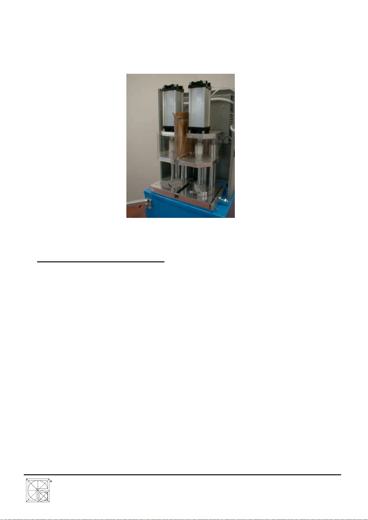
for WM1L/S WM1L/S-M WM1L/E Single
head machines
File: 1927.doc -25/01/02 11:55
2
TABLE OF CONTENTS
TABLE OF CONTENTS .......................................................................................................... 2
1. INTRODUCTION................................................................................................................. 3
2. GENERAL PRECAUTIONS................................................................................................. 3
3. CHARACTERISTICS........................................................................................................... 5
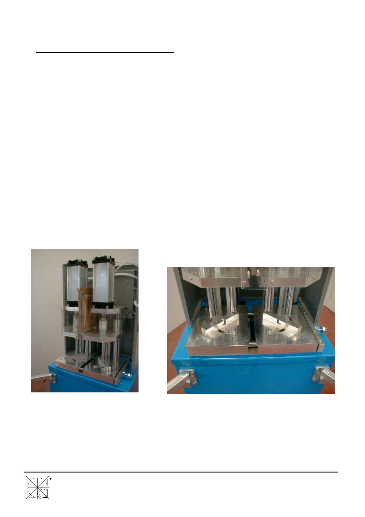
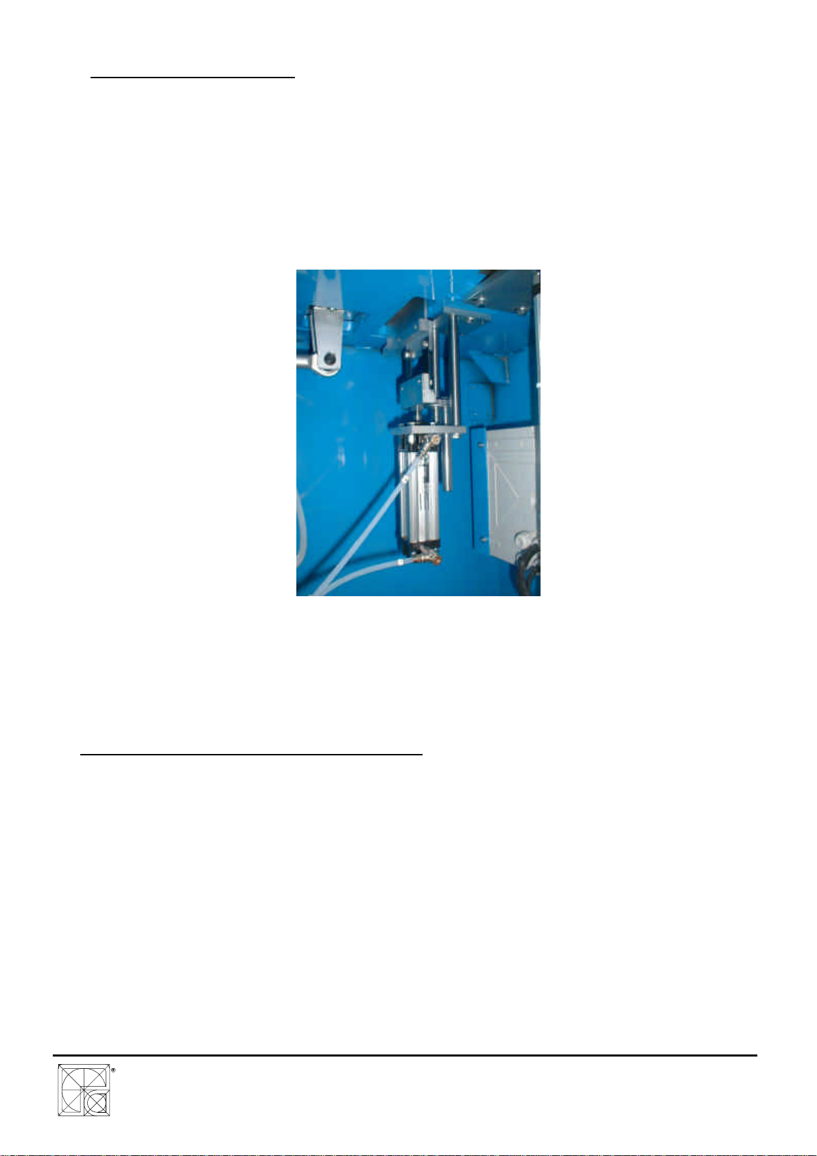
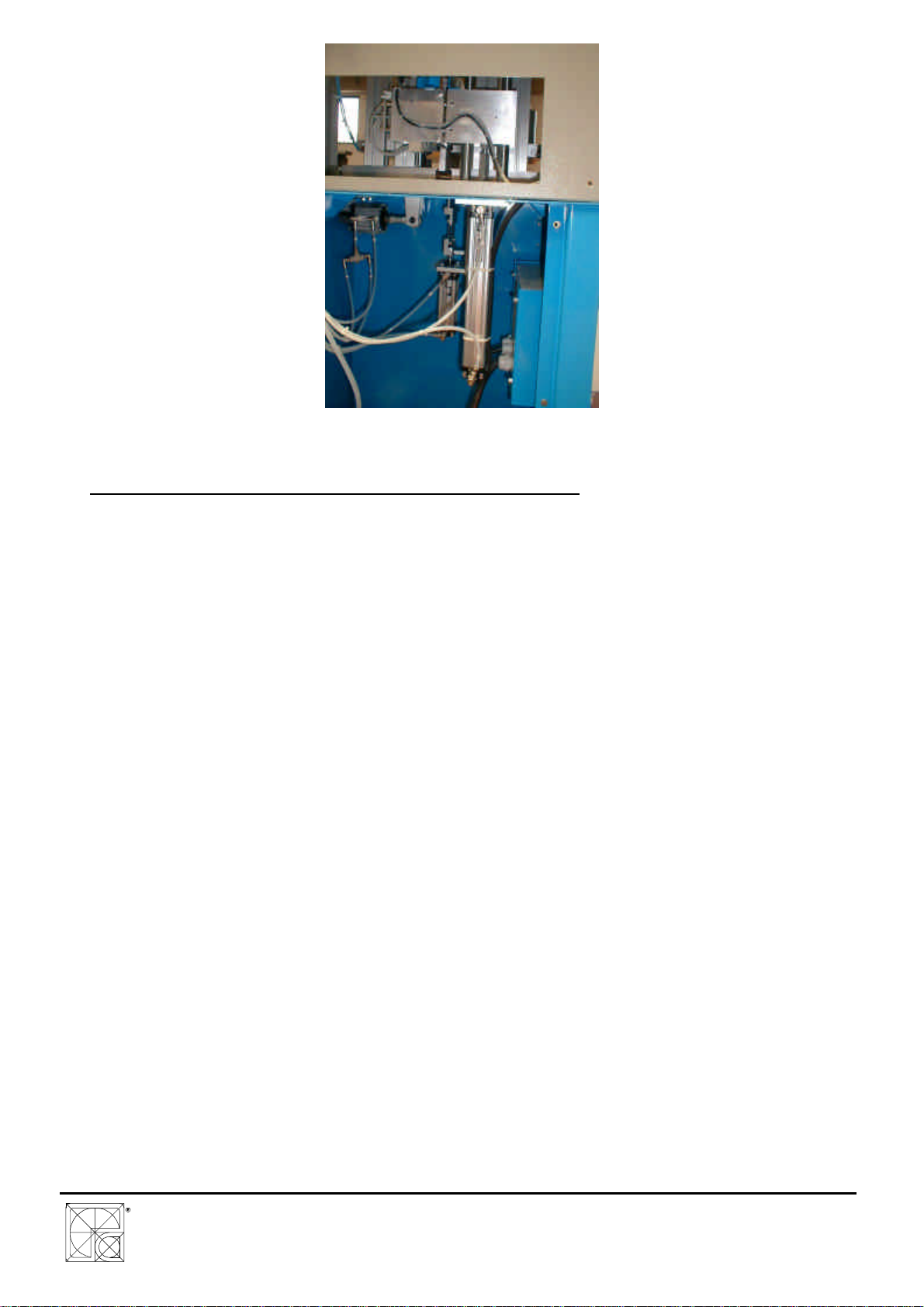
3.1 Description of the machine..................................................................................... 5
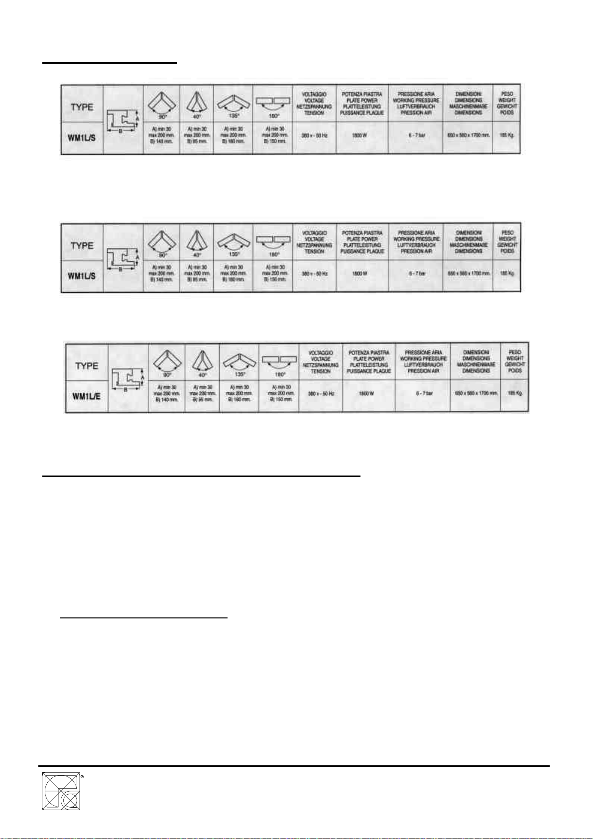
3.2 Technical features.................................................................................................. 9
3.3 Directly functioning components during welding .................................................... 9
3.3.1 Heating plate for fusion............................................................................ 9
3.3.2 Welding seal limitation blades ................................................................. 10
3.4 Use limits................................................................................................................ 12
3.4 Standard kits........................................................................................................... 12
3.5 Optional/Spare parts............................................................................................... 13
3.6 Conformity with safety standards............................................................................ 13
4. COMMISSIONING............................................................................................................... 14
4.1 Transport ................................................................................................................ 14
4.2 Positioning.............................................................................................................. 14
4.3 Safety zones and dimensions................................................................................. 15
4.4 Setting up for work.................................................................................................. 15
4.5 Compressed air circuit hook-up.............................................................................. 18
4.6 Connection of the electric equipment.....................................................................18
5. USE..................................................................................................................................... 19
5.1 Checks before use.................................................................................................. 19
5.2 Description of controls............................................................................................ 19
5.3 Operating cycle....................................................................................................... 22
5.4 Emergency device..................................................................................................25
5.5 Functionality of sensors.......................................................................................... 25
5.5.1 Inductive sensor........................................................................................ 25
5.5.2 Reed sensors............................................................................................ 26
5.5.3 Thermocouples ......................................................................................... 26
5.5.4 Welding at anlges different from 90°......................................................... 26
5.6 Precautions to ensure safety during use................................................................27
6. ADJUSTMENT OF WORKING PARAMETERS..................................................................28
6.1 Temperature of the heating plate ...........................................................................28
6.2 Temperature of welding seal limitaton blades (if installed)..................................... 29
6.3 Timer for warming-up.............................................................................................. 29
6.4 Cooling Timer.........................................................................................................30
6.5 Mechanical parameters for welding........................................................................ 30
SERVIZI .................................................................................................................................. 32
9.1 –PLATE CLEANING.............................................................................................. 32
9.2 –REPLACEMENT OF TEFLON.............................................................................. 33
9.3 –PROTECTED MENU ........................................................................................... 34
9.4 –RESET MEMORY................................................................................................ 34