Peterbilt 387 User manual

PART 1: INTRODUCTION HOW TO FIND WHAT YOU WANT
(R10/06) Y53-6007 – 3 –
PART 1: INTRODUCTION
This manual contains useful information for the safe and
efficient operation of your Peterbilt Model 387. It also pro-
vides information on maintaining your vehicle in the best
condition, with an outline for performing safety checks and
basic preventive maintenance inspections.
We have tried to present the information you’ll need to
learn about your vehicle’s functions, controls, and opera-
tion—and to present it as clearly as possible. We hope
you’ll find this manual easy to use.
Please remember, though—this manual is not a training
manual. It can’t tell you everything you need to know
about driving your Peterbilt vehicle. For that you need a
good training program or truck driving school. If you have
not been trained, get the proper training before you drive.
Only qualified drivers should drive this vehicle.
There will be times when you need to take this manual out
of your Peterbilt. When you do, please be sure to return it
to the cab when you are finished using it. That way it will
be there when you need it the next time or when you pass
the vehicle on to the next user.
How To Find What You Want
There are several tools built into this manual to help you
find what you need quickly and easily.
First is the Quick Table of Contents. Located at the front
of the manual, this lists the main subjects covered and
gives page numbers where you can find these subjects.
Use the Quick Table of Contents to find information on a
large subject like “Maintenance.”
Cross-referenced citations also help you get the informa-
tion you need. If some other part of the manual contains
further information on the subject you are reading about,
we’ll indicate that in a cross-reference like this: (See
“PART 6: DRIVER’S CHECKLIST”). You won’t have to go
searching for more information.
Finally you’ll find a helpful Subject Index. It’s in the back
of the manual and alphabetically lists the subjects cov-
ered. So if you want information on brakes, for example,
just look under Brake in the Subject Index. You’ll find all
the pages listed where brakes or braking are discussed.

A SPECIAL WORD ABOUT REPAIRS PART 1: INTRODUCTION
– 4 – Y53-6007 (R10/06)
A Special Word About Repairs
Your Peterbilt dealer’s service center is the best place to
have your vehicle repaired. You can find Peterbilt dealers all
over the country with the equipment and trained personnel
to get you back on the road quickly—and keep you there.
Your vehicle is a complex machine. Anyone attempting
repairs on it needs good mechanical training and the
proper tools. If you are sure you have these requirements,
then you can probably perform some repairs yourself.
However, all warranty repairs must be performed by an
authorized Peterbilt service facility. If you aren’t an experi-
enced mechanic, or don’t have the right equipment,
please leave all repairs to an authorized service facility.
They are the ones equipped to do the job safely and cor-
rectly.
WARNING! Attempting repair work without suf-
ficient training, service manuals, and the proper
tools can be dangerous. You could be injured or
you could make your truck unsafe. Do only
those tasks you are fully qualified to do.
Maintenance Manuals. If you do decide to do any com-
plex repair work, you’ll need the Peterbilt Maintenance
manuals. Order them from your authorized dealer. Please
provide your Chassis Serial Number when you order, to
be sure you get the correct manuals for your vehicle. Allow
about four weeks for delivery. There will be a charge for
these manuals.
Final Chassis Bill of Material. A complete, nonillustrated
computer printout listing of the parts used to custom-build
your Peterbilt vehicle is available through the Peterbilt
dealer from whom your purchased your vehicle.
WARNING! Modifying your vehicle can make it
unsafe. Some modifications can affect your
truck’s electrical system, stability, or other
important functions. Before modifying your
vehicle, check with your dealer to make sure it
can be done safely.
Additional Sources of Information
Operator’s manuals are also supplied by the manufactur-
ers of components such as the engine, seats, transmis-
sion, and radio in your Peterbilt. If you are missing any of
these manuals, ask your Peterbilt dealer to supply them.

PART 1: INTRODUCTION WARNINGS
(R10/06) Y53-6007 – 5 –
Your Model 387’s glove box also contains a copy of the
Truck Driver’s Handbook, published by the American
Trucking Association. Refer to it for important information
on driving your vehicle. Another place to learn more about
trucking is a local truck driving school. Contact one near
you to find out what kinds of instruction it offers.
Federal and state agencies also have information you can
ask for. The Interstate Commerce Commission can give
you information about regulations governing transporta-
tion across state lines. And various agencies in state gov-
ernments are sources for regulations that differ from state
to state.
Warnings
We’ve put a number of warning messages in this manual.
They are there for your protection and information. Please
read them and follow them. They can help you to avoid
injury to yourself and your passengers as well as to pre-
vent costly damage to your vehicle. We’ve used certain
symbols and “signal words” to indicate what kind of mes-
sage is going to follow. When you see these symbols &
words, you know that you need to pay special attention.
Please don’t ignore any of these signals.
WARNING! When you see this symbol & word,
the message that follows is especially vital.
This signals something that can cause seri-
ous injury or death. This message will tell you
what the hazard is, what can happen if you
don’t heed the warning, and how to avoid it.
For example:
WARNING! Attempting repair work without
sufficient training, service manuals, and the
proper tools can be dangerous. You could be
injured or you could make your vehicle
unsafe. Do only those tasks you are fully qual-
ified to do.
CAUTION: This symbol & word signals some-
thing that could damage your vehicle. You
might receive an injury, too. For example:
CAUTION: Continuing to operate a vehicle
with insufficient oil pressure will cause seri-
ous engine damage.
NOTE: Gives you information we feel you’d like to
have. It could have to do with care of your vehicle
or with driving more efficiently:

VEHICLE SAFETY PART 1: INTRODUCTION
– 6 – Y53-6007 (R10/06)
NOTE: A cold compressor can cause refrigerant
to liquefy and warp the valve plates or cause a
hydraulic lock. Warm the engine before starting
the air conditioner.
Please take the time to read these messages when you
see them. And remember:
WARNING! Something that could injure you seriously.
CAUTION: Something that could cause injury to you
or your vehicle.
NOTE: Useful information.
Vehicle Safety
Make sure your Peterbilt is in top working condition before
heading out on the road—it is the responsible driver's duty
to do so. Inspect the vehicle according to “PA R T 6 :
DRIVER’S CHECKLIST”.
WARNING! Do not drink and drive. Your
reflexes, perceptions, and judgment can be
affected by even a small amount of alcohol.
You could have a serious—or even fatal acci-
dent—if you drive after drinking. Please do
not drink and drive or ride with a driver who
has been drinking.
WARNING! The use of alcohol, drugs, and cer-
tain medications will seriously impair percep-
tion, reactions, and driving ability. These
circumstances can substantially increase the
risk of an accident and personal injury.
Please remember, this manual is not a training manual. It
cannot tell you everything you need to know about driving
your Peterbilt vehicle. For that you need a good training
program or truck driving school. If you have not been
trained, get the proper training before you drive. Only
qualified drivers should drive this vehicle.
Every new Peterbilt vehicle is designed to conform to all
Federal Motor Vehicle Safety Standards applicable at the
time of manufacture. However, even with these safety fea-
tures, continued safe and reliable operation depends
greatly upon regular vehicle maintenance. The vehicle
must be operated within the range of its mechanical capa-
bilities and the limits of its load ratings. (See the Tire and
Rim Weight Ratings label on the driver's door edge.)

PART 2: GETTING INTO & OUT OF THE CAB AND FRAME ACCESS
(R10/06) Y53-6007 – 7 –
PART 2: GETTING INTO & OUT OF THE CAB AND FRAME ACCESS
Be careful whenever you get into or out of your vehicle’s
cab. Always maintain at least three points of contact with
your hands on the grab handles and your feet on the
steps.
WARNING! Jumping out of the cab or getting
into the cab without proper caution is danger-
ous. You could slip and fall, possibly suffering
a serious injury. Keep steps clean. Clean any
fuel, oil, or grease off of the steps before
entering the cab. Use the steps and grab han-
dles provided, and always keep at least three
points of contact between your hands and
feet and the truck. Look where you are going.
The illustrations that follow show the best ways to enter
and exit a cab.
02958-A
Vehicle With External Grab Handle

02958-B
DOOR LOCK AND KEYS PART 2: GETTING INTO & OUT OF THE CAB AND FRAME ACCESS
– 8 – Y53-6007 (R10/06)
Vehicle Without External Grab Handle
Door Lock and Keys
Doors can be locked from the inside by using the lock but-
ton. Close the door then push the button down to lock.
Doors automatically unlock when you open them from
inside, and can be locked from the outside with the key
only.
WARNING! To lessen the chance and/or sever-
ity of personal injury in case of an accident,
always lock the doors while driving. Along
with using the lap/shoulder belts properly,
locking the doors helps prevent occupants
from being thrown from the vehicle.
To lock or unlock the doors from outside the cab, insert the
key in the lock. Turn the key toward the rear to lock; for-
ward to unlock.
Remote Keyless Entry (optional)
This vehicle may be equipped with a Remote Keyless
Entry (RKE) system that adds security and convenience
to your vehicle. The system will lock or unlock the driver’s
door and passenger’s door with the key fob and alert you
with parking lights when the selected door’s are locked or
unlocked. The system includes two key fobs that provide
secure rolling code technology that prevents someone
from recording the entry signal.
Operation
To Unlock The Driver’s Door

PART 2: GETTING INTO & OUT OF THE CAB AND FRAME ACCESS DOOR LOCK AND KEYS
(R10/06) Y53-6007 – 9 –
Press the UNLOCK button once. The driver's door will
unlock and the parking lights will come on for 40 sec-
onds.
To Unlock The Passenger’s Door
Press the UNLOCK button once and press again
within 5 seconds. The passenger door will unlock.
To Lock Both Doors
Press the LOCK button. The doors will lock and the
parking lights will come on for 2 seconds. If the doors
are open they will not lock. The range of the RKE sys-
tem should be approximately 30 ft. This will be
reduced if it is operated close to other RF sources
such as TV/radio transmitters and cell towers.
Batteries
The key fob uses one CR2032, 3V battery. Batteries
should last approximately three years, depending on use.
Consistently reduced range is an indicator that the battery
needs replacement. Batteries are available at most dis-
count, hardware and drug stores.
To Replace The Battery
1. Remove rear cover from key fob.
2. Remove the battery.
3. Install new battery.
4. Reinstall cover.
5. Synchronize the key fob.
Synchronization
The key fob may need to be synchronized to the truck
when the battery is replaced or when the key fob has not
been used for an extended period time.
To Synchronize A Key Fob
1. Hold the key fob near the receiver.
NOTE: The receiver is located behind the
Speedometer/Tachometer cluster assembly.
2. Press and hold both the Lock and Unlock buttons at
the same time for approximately 7 seconds.
3. When the key fob is resynchronized, the doors will
lock then immediately unlock.
4. If the fob fails to synchronize, it could be programmed
to a different truck or could have failed. Contact your
dealer to re-program your key fob.

CLIMBING ONTO THE DECK PLATE PART 2: GETTING INTO & OUT OF THE CAB AND FRAME ACCESS
– 10 – Y53-6007 (R10/06)
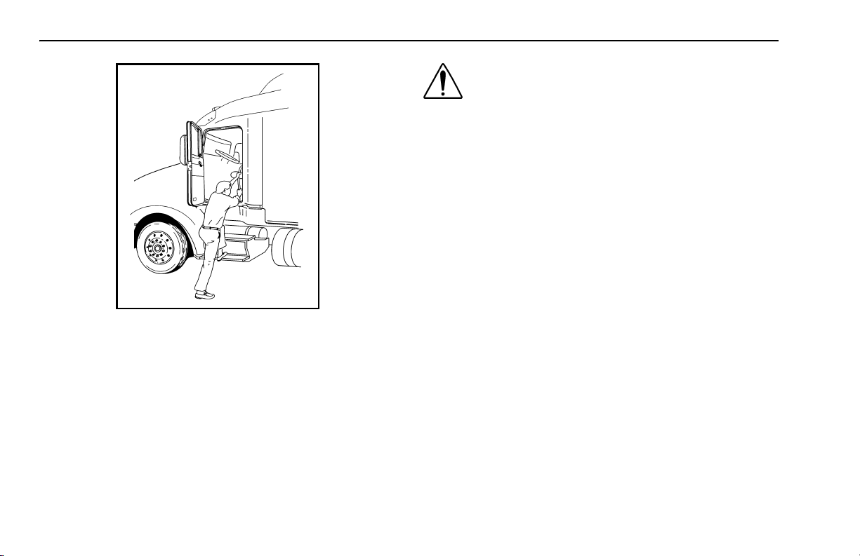
Climbing Onto the Deck Plate
When you are climbing onto and off the deck plate, main-
tain at least three points of contact with your hands on the
grab handles and your feet on the steps.
WARNING!
• You can be hurt if you aren’t careful climb-
ing onto and off the deck plate. You can slip
and fall, especially if the surfaces are wet or
icy, or if you step in oil, fuel, or grease. Keep
steps clean. Always maintain at least three
points of contact between your hands and
feet and the steps and deck plate.
• Do not climb onto and off the deckplate–use
steps and grabhandle provided. If there is
no deck plate, or if proper steps and grab
handles aren’t provided, don’t climb onto
the area behind the cab. Peterbilt did not
intend for the area to be a step if handrails
or proper steps are not provided.
WARNING! Do not step on vehicle compo-
nents without antiskid surfaces or use com-
ponents not designed for entry-and-exit use.
You could fall and injure yourself if you step
on a slippery surface. For example:
• You could fall and injure yourself if you step
onto a fuel tank surface. A fuel tank is not a
step. The tank surface can get very slippery,
and you might not be able to prevent a fall.
Don’t step onto the surface of a fuel tank.
Use only the steps and handholds provided,
not chain hooks, quarter fenders, etc.
• Always reinstall steps before entering the
cab or accessing the deck plate. Without
steps, you could slip and fall, resulting in
possible injury to yourself.
NOTE: Any alteration (adding bulkheads, head-
ache racks, tool boxes, etc.) behind the cab or
sleeper that affects the utilization of grab handles,
deck plates, or frame access steps installed by
Peterbilt must comply with FMCSR 399.
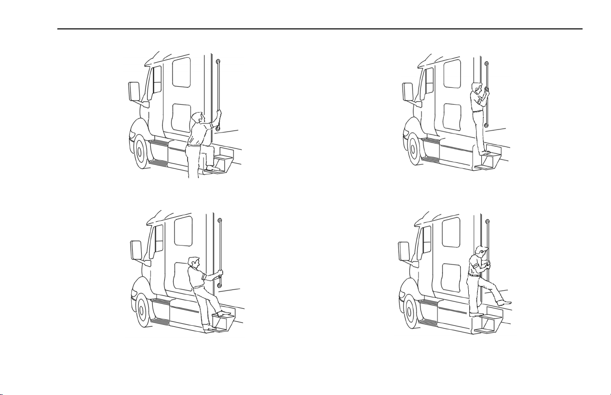
The pictures that follow show you the right way to get on
and off the area behind your cab.

PART 2: GETTING INTO & OUT OF THE CAB AND FRAME ACCESS CLIMBING ONTO THE DECK PLATE
(R10/06) Y53-6007 – 11 –
Hold handles as you step up
Three points of contact
Three points of contact as you reach the deck area
Three points of contact as you step to the deckplate

CLIMBING ONTO THE DECK PLATE PART 2: GETTING INTO & OUT OF THE CAB AND FRAME ACCESS
– 12 – Y53-6007 (R10/06)

PART 3: GETTING TO YOUR ENGINE HOOD TILT
(R10/06) Y53-6007 – 13 –
PART 3: GETTING TO YOUR ENGINE
Hood Tilt
Follow this procedure to tilt the hood.
WARNING! Before opening or closing the
hood, be sure there are no people or objects
in the way. A hood could hurt someone in the
way of its opening or descent.
1. To open your hood, find the hood release handle on
the cab floor beside the driver’s seat.
Hood
release
handle

HOOD TILT PART 3: GETTING TO YOUR ENGINE
– 14 – Y53-6007 (R10/06)
2. Grasp the lever and turn it towards you. The hood will
release and pop open to a neutral position, approxi-
mately 2” above the closed position.
WARNING! The hood uses hydraulic dampers
to control movement during opening. Do not
tilt the hood with these dampers discon-
nected. Replace damaged, worn, or leaking
dampers as soon as possible. Tilting a hood
with the dampers disconnected or defective
may cause the hood to tilt too rapidly. You
could be injured and the hood could be dam-
aged.
3. Proceed to the front of the vehicle and face the hood.
Grasp the hood ornament on the top of the crown
molding. Pull forward and down until the hood is fully
open and rotation stops.
WARNING! If the hood falls, anyone under it
could be injured. Always ensure that a hood is
fully tilted open any time anyone gets under a
hood for any reason.
4. To close the hood, firmly push upward and rearward
on the hood ornament to start the hood tilting back-
wards. Continue to push until the hood moves through
its neutral position. The hood will continue to tilt back-
wards. Apply a firm push to the hood ornament to
engage the hood latches located on both sides of the
firewall.
WARNING! If the hood is not latched securely,
it could open during operation and cause an
accident. Be sure the hood is latched securely
before moving the vehicle.

PART 4: CONTROLS AND DISPLAYS YOUR INSTRUMENT PANEL
(R10/06) Y53-6007 – 15 –
PART 4: CONTROLS AND DISPLAYS
This part explains the location of the various features on
your vehicle and describes their function. For information
on using these features in driving, see the paragraphs
below.
Your Instrument Panel
Please remember that each Model 387 is custom-made.
Your instrument panel may not look exactly like the one in
the pictures that follow.
We have tried to describe the most common features and
controls available, so your vehicle may not have some of
the ones that appear in this section. You can pick out the
parts that apply to you and read them to be fully informed
on how your particular vehicle operates.

YOUR INSTRUMENT PANEL PART 4: CONTROLS AND DISPLAYS
– 16 – Y53-6007 (R10/06)
Typical Cab Instruments and Controls
1
2
3
4
5
6789
16
02971B
17
18
15
12
10
13
14
11
LEFT SIDE
1. ID/Clearance Lamps Switch 10. Air Cleaner Restriction
2. Ignition Switch 11. Primary Air Pressure
3. Headlamps Switch 12. Secondary Air Pressure
4. Voltmeter 13. Fuel
5. Oil Pressure 14. SMC Select/Reset Switch
6. Tachometer 15. Dome Light Switch
7. Warning Light Bar 16.
Windshield Wiper/Washer
8. Speedometer-Message 17. Panel Dimmer
Center (SMC)
9. Water Temperature 18. Cigarette Lighter

1
2
3
4
5
6
7
8
9
10 11 12
13
14 15 16 17
18
19
21
02972A
20
PART 4: CONTROLS AND DISPLAYS YOUR INSTRUMENT PANEL
(R10/06) Y53-6007 – 17 –
RIGHT SIDE
1. Parking Brake Valve 12. Engine Brake
2. Trailer Air Supply Valve 13. Engine Brake
3. Heater/AC Control Panel 14. Load Lights Switch
4. Fog Lights Switch 15. Interaxle Differential Lock
Switch
5. Engine Fan Switch 16. 5th Wheel Lock Switch
6. ID/Clearance Lamps Flash 17. Air Suspension Switch
Switch
7. Trailer Brake Lever 18. Radio
8. Cruise Control Switch 19. CB Radio
9. Transmission Temperature 20. Selected Option Switch
10. Cruise Control Switch 21. Mirror Heater Switch
11. Pyrometer

STEERING COLUMN-MOUNTED CONTROLS PART 4: CONTROLS AND DISPLAYS
– 18 – Y53-6007 (R10/06)
Steering Column-Mounted Controls
Turn Signal and Indicator Lights
Turn Signal
Your turn signal lever is mounted on the left side of the
steering column below the steering wheel. Green direc-
tional indicator lights appear on the instrument panel.
NOTE: The ignition key must be turned to ON for
the signal/switch to operate.
To operate the signal, move the lever in the direction of the
turn.
WARNING! After you complete a turn, shut the
system off by returning the lever to the “OFF”
(center) position. The switch's lever action is
NOT self-canceling. Failure to shut off a turn
signal could confuse other drivers and result in
an injury accident. An indicator light in the
instrument panel will flash until the turn signal
is turned off.

PART 4: CONTROLS AND DISPLAYS STEERING COLUMN-MOUNTED CONTROLS
(R10/06) Y53-6007 – 19 –
Hazard Flasher
Hazard Flasher
The four-way Hazard Flasher switch is on the turn signal
body, just underneath the turn signal lever. It will operate
with the key switch in the ON or OFF position. Use your
hazard flasher whenever you are off the road or on the
side of the road, or in a potentially hazardous situation.
Pull it out to activate the system. All turn signals will flash
at once. To turn it off, move the turn signal lever up or
down.
WARNING! Use your Hazard Flasher Warning
System any time you have to stop off the road
or on the side of the road, day or night. A
hard-to-see vehicle can result in an injury
accident. Another vehicle could run into you if
you do not set your flashers. Always move the
vehicle a safe distance off the road when
stalled or stopped for repairs.
Of course, in normal stopping in traffic, such as at a stop
light, you do not use your flashers.
WARNING! Your disabled vehicle can be dan-
gerous for you and others. The hot exhaust
system could ignite dry grass, spilled fuel, or
other substances. Do not park or operate your
vehicle where the exhaust system could con-
tact dry grass, brush, spilled fuel, or any other
material that could cause a fire.

STEERING COLUMN-MOUNTED CONTROLS PART 4: CONTROLS AND DISPLAYS
– 20 – Y53-6007 (R10/06)
High Beam Headlights
High Beam Headlight Switch
All Peterbilt vehicles come equipped with a combination
turn signal and high beam/low beam switch. To switch
your headlights lower or higher, gently pull the turn signal
lever up, towards the steering wheel, until you hear the
switch “click” and the beam changes.
Electric Horn
Your Peterbilt has an electric horn. To sound the horn,
press on the bar in the center of the steering wheel
Electric Horn Bar
Air Horn
Your Model 387 has an air horn in addition to an electric
horn. Control the air horn by pulling on the lanyard extend-
ing from the overhead header panel.

PART 4: CONTROLS AND DISPLAYS STEERING COLUMN-MOUNTED CONTROLS
(R10/06) Y53-6007 – 21 –
Trailer Brake Hand Valve
02975A
This hand valve provides air pressure to apply the trailer
brakes only. It operates independently of the foot treadle
valve.
NOTE: The trailer brake is not to be used as the
main means of braking. To use this brake fre-
quently instead of using the foot brake will wear
out the trailer brake sooner.
To operate the trailer brake hand valve: pull down on
the lever under the right side of the steering wheel.
See the Index, under Brake Safety and Emergency for
more complete information on when and how to use your
trailer brake
WARNING!
• It is dangerous to use air-applied trailer
brakes for parking or holding a vehicle. Air
system pressure can bleed down and
release the brakes. You could have a vehi-
cle roll-away resulting in an accident. You or
others could be badly injured. Always apply
the parking brakes for parking or holding
your vehicle on grade.
• Grabbing the trailer brake hand lever
instead of the BrakeSaver lever could lead
to an accident. If you have these levers,
they may be close together on your steering
wheel column. Be sure you get the one you
want. The BrakeSaver lever is bent, while
the trailer parking brake lever is straight.

TILT-TELESCOPING STEERING COLUMN PART 4: CONTROLS AND DISPLAYS
– 22 – Y53-6007 (R10/06)
Tilt-Telescoping Steering Column
Tilt-Telescope Lever
The telescoping feature of the steering wheel allows for-
ward and rearward movement of the wheel. The tilting fea-
ture allows you to move the wheel up and down.
WARNING! Adjusting the Tilt-Telescoping
Steering Wheel while the vehicle is in motion
could cause loss of control. You would not be
able to steer properly and could have an acci-
dent. Make all adjustments to the steering
mechanism while the vehicle is stopped.
To position the wheel: Locate the Tilt-Telescope Lever
on the floor, to the left of the steering column. Push this
lever toward the floor. Move the steering wheel to the
desired angle and height. Release the lever to lock in the
correct position.
Dash-Mounted Features
Keys and Locks
The same key fits your ignition, doors, and sleeper lug-
gage compartment. Frame-mounted tool box locks, lock-
ing fuel tank caps, and glove boxes each have individual
keys.
Table of contents
Other Peterbilt Truck manuals

Peterbilt
Peterbilt 348 2017 User manual

Peterbilt
Peterbilt 365 User manual

Peterbilt
Peterbilt 210 User manual

Peterbilt
Peterbilt 389 2017 User manual

Peterbilt
Peterbilt 579 User manual

Peterbilt
Peterbilt 320 User manual

Peterbilt
Peterbilt 220 User manual

Peterbilt
Peterbilt 330 User manual

Peterbilt
Peterbilt 389 2017 User manual

Peterbilt
Peterbilt 220 User manual