Pfaff Industrial 8312 User manual

8312
INSTRUCTION MANUAL
296-12-18 975/002
Betriebsanleitung engl. 02.10
This instruction manual applies to machines
from serial number 10 030 037 and software
version 3.1 onwards

The reprinting, copying or translation of PFAFF Instruction Manuals, whether in whole or
in part, is only permitted with our previous authorization and with written reference to the
source.
PFAFF Industriesysteme
und Maschinen AG
Hans-Geiger-Str. 12 - IG Nord
D-67661 Kaiserslautern

Contents
Contents Page
1Safety..................................................................................................................................................... 5
1.01 Directives ................................................................................................................................................ 5
1.02 General notes on safety.......................................................................................................................... 5
1.03 Safety symbols ....................................................................................................................................... 6
1.04 Important notes for the user.................................................................................................................... 6
1.05 Operating and technical staff .................................................................................................................. 7
1.05.01 Operating staff ........................................................................................................................................ 7
1.05.02 Technical staff......................................................................................................................................... 7
1.06 Danger.................................................................................................................................................... 8
2Proper use ............................................................................................................................................. 9
3Specifications ..................................................................................................................................... 10
4Disposal of machine........................................................................................................................... 11
5Transportation, packing and storage................................................................................................ 12
5.01 Transportation to customer’s premises................................................................................................. 12
5.02 Transportation inside customer’s premises........................................................................................... 12
5.03 Disposal of packing materials ............................................................................................................... 12
5.04 Storage ................................................................................................................................................. 12
6Explanation of symbols...................................................................................................................... 13
7Controls ............................................................................................................................................... 14
7.01 Summary of control elements ............................................................................................................... 14
7.02 Control panel ........................................................................................................................................ 15
7.03 Pedal..................................................................................................................................................... 16
7.04 Knee switch (optional)........................................................................................................................... 17
8Installation and commissioning ........................................................................................................ 18
8.01 Installation............................................................................................................................................. 18
8.02 Commissioning ..................................................................................................................................... 19
8.03 Switching the machine on/off ................................................................................................................ 19

Contents
Contents Page
9Preparation .......................................................................................................................................... 20
9.01 Adjusting the feed roller clearance (roller gap)...................................................................................... 20
9.02 Selecting the sealing mode and the pedal mode .................................................................................. 21
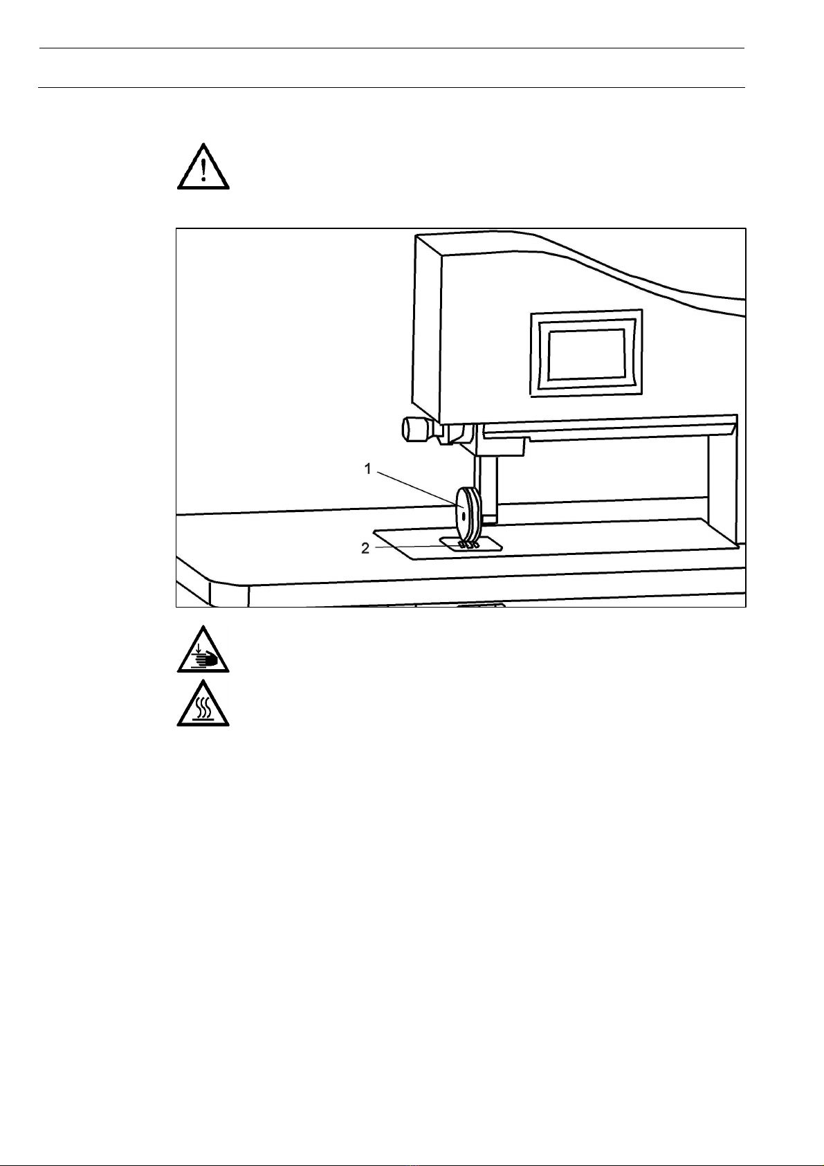
9.03 Secondary feed rollers .......................................................................................................................... 22
10 Sealing ................................................................................................................................................. 23
10.01 Sealing principle.................................................................................................................................... 23
10.02 Sealing modes ...................................................................................................................................... 23
10.02.01 Standard sealing with specified amplitude (amplitude sealing) ............................................................. 24
10.02.02 Standard sealing with specified power (power sealing)......................................................................... 25
10.02.03 Dynamic sealing with specified amplitude............................................................................................. 27
10.02.04 Dynamic sealing with specified power................................................................................................... 28
10.02.05 Basting .................................................................................................................................................. 29
10.03 Sealing formulas ................................................................................................................................... 30
11 Input ..................................................................................................................................................... 31
11.01 Main menu input ................................................................................................................................... 31
11.02 Data management................................................................................................................................. 32
11.03 Settings menu ....................................................................................................................................... 33
11.04 Service menu ........................................................................................................................................ 34
11.05 Blocking the feed roller.......................................................................................................................... 35
11.06 Setting feed roller parameters............................................................................................................... 36
11.07 Setting the neutral point of the feed roller ............................................................................................. 37
11.08 PIN code menu ..................................................................................................................................... 38
11.09 Adjusting the clock time ........................................................................................................................ 40
11.10 Adjusting the current of the drive motors............................................................................................... 41
11.11 Setting the machine configuration......................................................................................................... 42
11.12 Changing the contrast of the control panel display ............................................................................... 43
11.13 Rental menu.......................................................................................................................................... 44
12 Maintenance and self help ................................................................................................................. 45
12.01 Cleaning and care................................................................................................................................. 45
12.02 Protective switch ................................................................................................................................... 45
12.03 Changing feed roller.............................................................................................................................. 46
12.04 Error messages..................................................................................................................................... 47
12.05 Circuit diagrams .................................................................................................................................... 48

Safety
5
1 Safety
1.01 Directives
This machine is constructed in accordance with the European regulations indicated in the conformity
and manufacturer’s declarations.
In addition to this instruction manual, please also observe all generally accepted, statutory and other
legal requirements, including those of the user’s country, and the applicable environmental protection
regulations! The valid regulations of the regional social insurance society for occupational accidents or
other supervisory authorities are to be strictly adhered to!
1.02 General notes on safety
The machine may only be operated by adequately trained operators and only after these have read
the appropriate instruction manual!
The hazard and safety instructions attached to the machine must be followed!
The machine may only be used for the purpose intended and may not be operated without its safety
devices. All relevant safety regulations must be adhered to.
When leaving unattended or during maintenance work, the machine must be disconnected from the
power supply by operating the main switch or by pulling out the plug!
Daily maintenance work may only be carried out by appropriately trained personnel!
Repair work and special maintenance work may only be carried out by specialists or appropriately
trained personnel.
Work on electrical equipment may only be carried out by appropriately trained personnel!
Work is not permitted on parts and equipment which are connected to the power supply! Exceptions
to this rule are found in the regulation EN 50110.
Modifications and alterations to the machine may only be carried out under observance of all
relevant safety operations!
Only spare parts which have been approved by us are to be used for repairs! We draw special
attention to the fact that spare parts and accessories not supplied by us have not been subjected to
testing nor approval by us. Fitting and/or use of any such parts may cause negative changes to the
design characteristics of the machine. We shall not accept any liability for damage caused by the
use of non-original parts.

Safety
6
1.03 Safety symbols
Danger!
Special points to observe.
Danger of hand injuries!
Danger of burns from hot surface!
Danger from electric voltage!
1.04 Important notes for the user
This instruction manual is part of the equipment of the machine and must be available to the
operating staff at all times.
This instruction manual must be read before the machine is operated for the first time.
Both operating and technical staff must be instructed on the safety devices of the machine and on
safe working methods.
It is the duty of the user to operate the machine only in perfect running order.
The user must ensure that none of the safety devices are removed nor put out of working order.
The user must ensure that only authorized persons operate and work on the machine.
The user must make sure there is no high-frequency welding equipment being operated in direct
proximity to the machine that exceeds the EMC limit values according to EN 60204-31 for the
machine.
For further information please refer to your PFAFF agency.

Safety
7
1.05 Operating and technical staff
1.05.01 Operating staff
Operating staff are the persons responsible for setting up, operating and cleaning the machine and for
removing any disturbances in the sewing area.
The operating staff is obliged to observe the following points, and must:
always observe the notes on safety in this instruction manual!
avoid using any working methods which adversely affect the safety of the machine!
avoid wearing loose-fitting clothing or jewelry such as necklaces or rings!
also ensure that only authorized persons are allowed near the danger area of the machine!
immediately report to the user any changes to the machine that may affect its safety!
1.05.02 Technical staff
Technical staff are persons who have been trained in electrical engineering, electronics and
mechanical engineering. They are responsible for lubricating, servicing and repairing the machine.
The technical staff is obliged to observe the following points, and must:
always observe the notes on safety in this instruction manual!
switch off the on/off switch before carrying out any maintenance and repair work on the machine!
never work on parts or equipment still connected to the power supply! Exceptions to this are only
permissible according to regulations EN 50110.
replace all safety covers after maintenance and repair work!

Safety
8
1.06 Danger
When the machine is in operation, a work area of 1 m must be kept free in front of and
behind the machine, so that access to the machine is possible at all times without
difficulty.
During operation do not place your hands in the area of feed roller 1and sonotrode 2!
Danger of fingers being drawn in and crushed!
During operation do not touch sonotrode 2!
Danger of burns from the heat-generating surface!

Proper use
9
2 Proper use
The PFAFF 8312 is used for continuous sealing of thin, thermoplastic materials, such as e.g. fleeces,
felts, woven and knitted fabrics using ultrasonics.
Any use of the machine which is not approved by the manufacturer shall be considered
improper use! The manufacturer shall not be liable for any damage arising out of
improper use! Proper use shall also be considered to include compliance with the
operation, adjustment, service and repair measures specified by the manufacturer!

Specifications
10
3 Specifications
Measures and weight
Depth: 800 mm
Width: 1200 mm
Height: 1310 mm
Weight: 127 kg
Clearance Width: 410 mm
Clearance under the rollers: max. 30 mm
Connection data
Operating voltage: 230 V ± 10 %, 50/60 Hz, 1-phase
Max. capacity: 1000 VA
Fuse: 1 x 16 A, inert
Performance data
Sealing pressure: 64 – 500 N
Sealing power: max. 400 W
Sealing speed: 0,1 – 11,8 m/min*
Seam width: max. 10 mm
Noise data
Emission sound level at the workplace: LpA < 70 dB(A)
(Noise measurement in accordance with 45 635-48-A-1, ISO 11204, ISO 3744, ISO 4871)
▲Subject to alterations
* depending on feed roller diameter, max. speed at roller diameter 80 mm
KpA = 2,5 dB

Disposal of machine
11
4 Disposal of machine
Proper disposal of the machine is the responsibility of the customer.
The materials used for the machine are steel, aluminium, brass and various plastic materials. The
electrical equipment comprises plastic materials and copper.
The machine is to be disposed of according to the locally valid pollution control regulations; if
necessary, a specialist is to be commissioned.
Care must be taken that parts soiled with lubricants are disposed of separately according
to the locally valid pollution control regulations!

Transportation, packing and storage
12
5 Transportation, packing and storage
5.01 Transportation to customer’s premises
The machines are delivered completely packed.
5.02 Transportation inside customer’s premises
The manufacturer cannot be made liable for transportation inside the customer‘s premises nor to other
operating locations. It must be ensured that the machines are only transported in an upright position.
5.03 Disposal of packing materials
The packing materials of this machine comprise paper, cardboard and VCE fibre. Proper disposal of
the packing material is the responsibility of the customer.
5.04 Storage
If the machine is not in use, it can be stored as it is for a period of up to six months, but should be
protected against dust and moisture.
If the machine is stored for longer periods, the individual parts, especially the surfaces of moving parts,
must be protected against corrosion, e.g. by a film of oil.

Explanation of symbols
13
6 Explanation of symbols
In this instruction manual, work to be carried out or important information is accentuated by symbols.
These symbols have the following meanings:
Note, information
Cleaning, care
Maintenance, repairs, adjustment, service work (only to be carried out by technical
staff)

Controls
14
7 Controls
7.01 Summary of control elements
Main switch 1,see section 8.03, p. 19
Control panel 2, see section 7.02, p. 15
Adjustment screw 3, see section 9.01, p. 20
Feed roller 4(depicted comprising two feed wheels and a cutting wheel)
Sonotrode 5
Secondary feed rollers 6, see section 9.03, p. 22
Generator 7
Pedal 8, see section 7.03, p. 16
USB port 9, accessible from back
Control box 10, accessible from back
Knee switch 11, optional accessory, see section 7.04, p. 17
Height adjustment of secondary feed rollers 12, see section 9.03, p. 22

Controls
15
7.02 Control panel
The control panel serves as both a display and an input device. Depending on the operating condition
of the machine different menus will be shown. Within the menus all symbols and texts in rounded
frames can be used as keys to activate functions or different menus. Activated functions are shown
with inverted symbols. Unframed symbols or texts as well as those in cornered frames are only used
for display purposes.
Values that are computed and controlled by the machine are merely displayed. Values determined and
changeable by the user can be entered numerically. By pressing a figure on the display a numeric
keypad is activated as shown below.
Erases the entered figures one by one, starting with
the last.
Cancels, entered value will not be taken over.
Enters negative values. (Only where permissible)
Numeric keypad, shown with the
example of „altering the sealing
amplitude“
Concludes the input, value will be taken over. Input
values that are not permissible will automatically be
rounded up or down.

Controls
16
Summary of the most frequently used symbols with related functions
Increases displayed value (alternative to numeric input as shown above)
Decreases displayed value (alternative to numeric input as shown above)
Changes to operating mode input (main menu), see Chapter 11, p. 31 ff.
Calls up service menu, see section 11.04, p. 34
Calls up settings menu, see section 11.03, p. 33
Changes to operating mode sealing, see Chapter 10, p. 23
Changes to basting mode, see section 10.02.05, p. 28
Display of current time in hours, minutes and seconds. Clock time adjustment see
section 11.09, p. 40
Starts sealing.
Stops sealing.
Shows the formula number. Sealing parameters are stored under a formula number and
can be recalled by it, see section 10.03, p. 30.
For further functions and their description see chapters Sealing and Input.
7.03 Pedal
The pedal can be operated forwards 1as well as backwards 2. The pedal function depends on the
sealing mode and pedal mode currently in use, see section 9.02, p. 21.
Pedal function in level mode:
Kick pedal partially forward: feed roller will be lowered to sealing position.

Controls
17
Kick pedal fully forward and hold: sealing will start and continue as long as pedal is being held.
Release pedal: sealing stops.
Kick pedal partially backward: feed roller will be lifted, the applicable gauge can be set in the feed
roller parameters menu, see section 11.06, p. 36.
Kick pedal fully backward: feed roller will be elevated completely.
Pedal function in flip-flop mode:
Kick pedal forward: feed roller will be lowered to sealing position. Sealing will start and continue
even after pedal is released.
Kick pedal forward again: sealing will stop.
Kick pedal partially backward: sealing will stop, feed roller will be lifted, the applicable gauge can be
set in the feed roller parameters menu, see section 11.06, p. 36.
Kick pedal fully backward: sealing will stop, feed roller will be elevated completely.
Pedal function in dynamic sealing mode (pedal mode dynamic):
Kick pedal forward: sealing parameters will be controlled within the values set by the operator in
proportion to the pedal position. (Dynamic sealing with specified amplitude see section 10.02.03,
p. 27, dynamic sealing with specified power see section 10.02.04, p. 28.)
Other functions as in level mode, see above.
Pedal function in basting mode
Kick pedal forward: a basting cycle (short, spotty sealing cycle) will be performed with the settings
displayed in the control panel.
7.04 Knee switch (optional)
Pushing the knee switch (fig. 11, ill. p. 14) will immediately start a basting cycle (short, spotty sealing
cycle) without previously activating the basting mode in the control panel (basting mode see
section 10.02.05, p. 28). A basting cycle set off using the knee switch is performed with the parameters
last set in the basting mode.
The knee switch can be obtained as an accessory.

Installation and commissioning
18
8 Installation and commissioning
After the machine has been unpacked, check it for any damages caused during transportation. If there
is any damage, please notify the transport company and your local PFAFF agency.
The machine must only be installed and commissioned by qualified personnel. All
relevant safety regulations must be strictly adhered to!
8.01 Installation
A suitable connection for electricity must be available at the machine’s location, see Chapter 3
Specifications, p. 10. An even and firm foundation as well as sufficient lighting must also be available at
the machine’s location.
Slide the machine off the pallet.
If the foundation is not completely even
the machine must be stabilized using the
adjustable foot at the right back end of
the machine. Loosen the lock nut 2
with a
suitable wrench and turn the adjusting
screw 1with a suitable screwdriver to the
right or left until the machine stands
steady. Hold the adjusting screw 1with
the screwdriver
in position and tighten the
lock nut 2.
Connect the plugs from the pedal and from any existing knee switch to the control box.

Installation and
commissioning
19
8.02 Commissioning
Clean the machine thoroughly if necessary.
Check the machine, particularly its electrical wiring, for any damage.
Have a qualified person check whether the motor can be driven with the existing power voltage.
If there are any differences, the machine must definitely not be operated!
The machine must only be connected to a suitably grounded socket!
8.03 Switching the machine on/off
To switch on the machine, turn the
main switch (location of the switch see
section 7.01, p. 14) to position 1. After
approximately 30 seconds the control
panel will display the base menu last
called up, before the machine was
switched off, see Chapter 10 Sealing,
p. 23 ff.
To switch off the machine, turn the main switch to position 0.

Preparation
20
9 Preparation
All regulations and notes in this manual must be observed! Special attention must be
paid to the safety regulations!
All setting-up work must only be carried out by personnel with the appropriate training!
9.01 Adjusting the feed roller clearance (roller gap)
Before starting to seal, the gap between feed roller and sonotrode must be adjusted manually –
depending on the material to be sealed and the sealing parameters set. The adjustment can be made
from any of the sealing menus (see p. 23 ff.).
Switch on the machine.
Lower feed roller.
Adjust the roller gap with the adjustment
screw 1:
Turn towards +: gap will be extended.
Turn towards -: gap will be minimized.
After replacing the feed roller, the diameter (see section 11.06, p. 36) and the neutral point (see
section 11.07, p 37) of the feed roller must be set before adjusting the roller gap.
Table of contents